wiring-diagram-flake-ice-machine.pdf
100%

Wiring Diagram Flake Ice Machine


HTTP://MYDIAGRAM.ONLINE
Revision 3.5 (04/2017)
© 2017 HTTP://MYDIAGRAM.ONLINE. All Rights Reserved.

TABLE OF CONTENTS

Cover1
Table of Contents2
AIR CONDITIONING3
ANTI-LOCK BRAKES4
ANTI-THEFT5
BODY CONTROL MODULES6
COMPUTER DATA LINES7
COOLING FAN8
CRUISE CONTROL9
DEFOGGERS10
ELECTRONIC SUSPENSION11
ENGINE PERFORMANCE12
EXTERIOR LIGHTS13
GROUND DISTRIBUTION14
HEADLIGHTS15
HORN16
INSTRUMENT CLUSTER17
INTERIOR LIGHTS18
POWER DISTRIBUTION19
POWER DOOR LOCKS20
POWER MIRRORS21
POWER SEATS22
POWER WINDOWS23
RADIO24
SHIFT INTERLOCK25
STARTING/CHARGING26
SUPPLEMENTAL RESTRAINTS27
TRANSMISSION28
TRUNK, TAILGATE, FUEL DOOR29
WARNING SYSTEMS30
WIPER/WASHER31
Diagnostic Flowchart #332
Diagnostic Flowchart #433
Case Study #1 - Real-World Failure34
Case Study #2 - Real-World Failure35
Case Study #3 - Real-World Failure36
Case Study #4 - Real-World Failure37
Case Study #5 - Real-World Failure38
Case Study #6 - Real-World Failure39
Hands-On Lab #1 - Measurement Practice40
Hands-On Lab #2 - Measurement Practice41
Hands-On Lab #3 - Measurement Practice42
Hands-On Lab #4 - Measurement Practice43
Hands-On Lab #5 - Measurement Practice44
Hands-On Lab #6 - Measurement Practice45
Checklist & Form #1 - Quality Verification46
Checklist & Form #2 - Quality Verification47
Checklist & Form #3 - Quality Verification48
Checklist & Form #4 - Quality Verification49
AIR CONDITIONING Page 3

Every power network, whether in a vehicle, manufacturing facility, or home appliance, relies on two fundamental pillars: **power distribution** and **grounding**. Without them, even the most advanced circuits would malfunction within seconds. This guide explores how electricity travels from its source to each load, how grounding stabilizes voltage levels, and how these two principles define the reliability and safety of every wiring system featured in Wiring Diagram Flake Ice Machine (Ice Machine, 2026, http://mydiagram.online, https://http://mydiagram.online/wiring-diagram-flake-ice-machine/MYDIAGRAM.ONLINE).

In any network of wires, current must always have a complete pathfrom the power source to the load and back through the ground or return line. Power distribution handles the delivery of energy, while grounding ensures that the system maintains a reference point close to zero volts. Together, they create the electrical loop that allows every motor, sensor, or controller to function as intended. Understanding this loop is essential for anyone who wants to troubleshoot or design electrical systems correctly.

Power distribution begins at the supply. In vehicles, its the battery or alternator; in buildings, its the main circuit panel; and in factories, it might be a three-phase transformer. The goal is to deliver consistent voltage to each branch circuit, ensuring no device receives too much or too little. The distribution path often includes switching relays, protective fuses, overload protectors, and connectors that isolate faults and protect sensitive electronics. A single bad connection or corroded fuse can drop voltage across the line, causing sensors to malfunction or actuators to operate erratically.

Grounding, on the other hand, serves as the stabilizing backbone of the entire system. Every piece of equipment must have a reliable ground connection to discharge stray current and prevent voltage buildup. Without proper grounding, static electricity, electromagnetic interference, and short circuits can cause erratic readings or even damage expensive modules. In an automotive context, the vehicle chassis often acts as a shared ground; in industrial panels, grounding bars connect all metallic enclosures to a dedicated earth rod. Proper grounding equals system stability thats a universal truth across Ice Machine and beyond.

When troubleshooting electrical problems, poor grounding is one of the most common culprits. A weak or corroded ground connection can mimic almost any fault intermittent lights, communication errors, or unexplained resets in control modules. Thats why professional technicians always start diagnostics by verifying voltage drop between ground points. A good rule of thumb is that no ground connection should drop more than **0.1 volts** under load. Anything higher indicates resistance that must be cleaned or repaired immediately.

Proper wiring design also ensures that current flow remains balanced. For example, heavy loads like motors should have thicker cables and separate grounds to prevent noise interference with low-voltage sensor circuits. Signal grounds, chassis grounds, and power grounds must be routed carefully to avoid feedback loops. In industrial automation, engineers often implement **star grounding**, where all grounds converge to a single point to minimize potential differences. This strategy prevents erratic readings in analog sensors and reduces communication errors on data buses.

Modern systems integrate **ground fault detection** to monitor leakage currents and automatically disconnect power if a fault is detected. This adds another layer of protection for both operators and equipment. Residual current devices (RCDs) and ground fault circuit interrupters (GFCIs) are common in residential and industrial environments, ensuring that stray current never becomes a safety hazard. These innovations reflect the evolution of safety standards recognized globally and practiced in facilities across Ice Machine.

Another key factor in power distribution is **voltage regulation**. Long wire runs or undersized cables can cause significant voltage drops, especially in high-current circuits. Using the correct wire gauge is crucial not only for performance but also for safety. Underrated cables heat up under load and can become a fire risk. Engineers calculate cable sizes based on current draw, material resistance, and permissible voltage loss. Regular maintenance, including checking torque on terminal screws and inspecting for oxidation, ensures that every joint maintains low resistance over time.

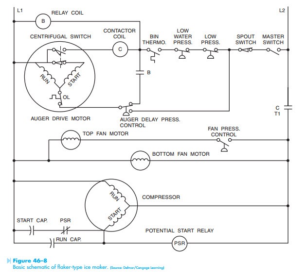
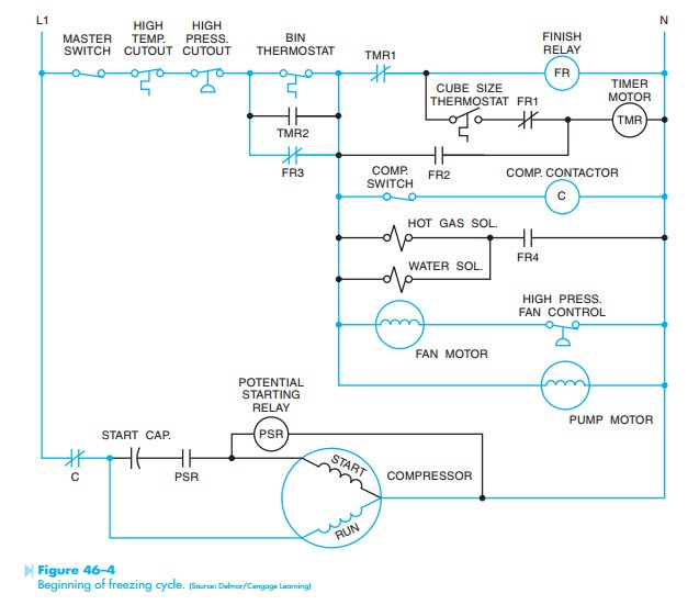
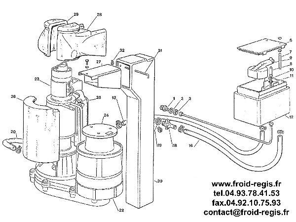
When it comes to documentation, detailed wiring diagrams serve as the map of the entire power and ground network. They show how each branch connects, where protective devices are located, and how current returns to the source. By following the diagram, technicians can isolate sections, perform continuity tests, and verify that each load receives proper voltage. The ability to read and understand these schematics turns complex troubleshooting into a logical, step-by-step process an approach fully explained throughout Wiring Diagram Flake Ice Machine.

In short, **power distribution delivers energy**, and **grounding keeps that energy under control**. Without either, no circuit could operate safely or predictably. Together, they define the health of every electrical system from the smallest sensor to the largest industrial controller. Understanding how to design, inspect, and maintain these two elements will make you far more effective in diagnosing faults and preventing downtime. Once you appreciate how current travels through every wire, and how grounding ensures balance and safety, wiring diagrams will no longer look like tangled lines but like living systems organized, logical, and perfectly engineered to make machines work, no matter the application or the year 2026.

Figure 1
ANTI-LOCK BRAKES Page 4

Before opening any electrical panel, read the warning labels carefully. Kill the main breaker and lock/tag it to prevent reactivation. Also isolate any backup sources such as UPS units or solar inverters. Choose PPE and test gear with a voltage rating comfortably above what you’re working on.

Handle wires gently and with method, not force. Don’t drop tools where they can bridge terminals and cause a short. Keep data cables and power cables on separate routes. Inspect pin alignment before you push a connector together. Clean dust or oil residues that can lower insulation resistance.

After completing the job, inspect visually and verify continuity. Verify that bolts are tight and wiring is re-secured in its mounts. Reconnect power gradually while monitoring for noise or abnormal heating. Sticking to a consistent process prevents damage and keeps people safe.

Figure 2
ANTI-THEFT Page 5

Abbreviations also describe operating state, not just component identity. IGN RUN, IGN ACC, and IGN START are all different positions of the ignition circuit, and each powers different branches at different times. Some coils only energize during START, while certain sensors only get their 5V REF in RUN; the “Wiring Diagram Flake Ice Machine” print shows this timing.

Symbols next to those state labels tell you whether a switch is normally open or normally closed, and whether loss of power means OFF or ON. That’s critical during testing, because what looks “dead” might just be a circuit that isn’t supposed to be live in that key position in Ice Machine. If you misread runtime state, you’ll order parts you didn’t need and that cost rolls back to http://mydiagram.online in 2026.

Best practice in 2026: read the icon plus the short code before declaring a circuit bad, then write down your key position and meter reading in https://http://mydiagram.online/wiring-diagram-flake-ice-machine/MYDIAGRAM.ONLINE. That protects you on warranty claims and gives the next tech a clean trail on “Wiring Diagram Flake Ice Machine”. It also keeps site liability clean for http://mydiagram.online in Ice Machine because there’s a timestamped record of what state the system was in when you tested it.

Figure 3
BODY CONTROL MODULES Page 6

Wire color coding and sizing together establish the visual and functional base of all safe electrical installations.
If these standards didn’t exist, technicians couldn’t safely distinguish between power, signal, or ground circuits.
Red = voltage, black/brown = ground, yellow = switch/ignition, and blue = communication — the universal color code for wiring.
By following color standards, engineers can quickly trace wires, identify roles, and avoid costly mistakes.
Adhering to color conventions keeps “Wiring Diagram Flake Ice Machine” compatible with global maintenance standards and practices.

Wire gauge, measured in AWG or square millimeters, is just as important as color.
It defines the wire’s ability to carry current, resist heat, and maintain mechanical strength under vibration or stress.
Smaller gauge numbers equal thicker wires suitable for power, while higher numbers mean thinner signal lines.
In Ice Machine, standards such as ISO 6722, SAE J1128, and IEC 60228 are widely adopted to ensure consistent wire quality and cross-compatibility between manufacturers.
Selecting the correct gauge keeps voltage levels stable, prevents overheating, and extends the lifespan of both wiring and connected components in “Wiring Diagram Flake Ice Machine”.
Gauge inaccuracies create uneven current distribution that harms efficiency and long-term reliability.

After wiring, thorough documentation and testing mark the completion of professional electrical work.
Every connection, wire color, and size must be recorded carefully in the service log.
If substitutes or alternate routes are used, they must be labeled and photographed for traceability.
After verification, all schematics, test results, and visual evidence should be uploaded to http://mydiagram.online for centralized storage.
Recording year (2026) and resource link (https://http://mydiagram.online/wiring-diagram-flake-ice-machine/MYDIAGRAM.ONLINE) guarantees traceable installation records for future analysis.
By following proper records and verification, “Wiring Diagram Flake Ice Machine” remains reliable and compliant with professional electrical standards.

Figure 4
COMPUTER DATA LINES Page 7

Power distribution describes the organized flow, regulation, and protection of energy across the system.
It maintains voltage stability, current balance, and steady energy delivery to every part of “Wiring Diagram Flake Ice Machine”.
Without effective distribution, power fluctuations could cause inefficiency, overheating, or total equipment failure.
Proper layout planning ensures energy is routed safely, devices are protected, and interference is minimized.
This structure guarantees that the entire system operates safely and reliably even under demanding conditions.

Building a dependable power system requires detailed calculations and strict adherence to technical standards.
Every conductor and fuse must match its expected current, total length, and tolerance range.
Within Ice Machine, ISO 16750, IEC 61000, and SAE J1113 define benchmarks for consistent electrical design.
Separate high-voltage conductors from signal cables to eliminate electromagnetic crosstalk.
Grounding and fuse terminals must be placed logically to simplify inspection and maintenance.
Good design ensures “Wiring Diagram Flake Ice Machine” operates consistently with minimal risk of voltage fluctuation.

Testing and documentation complete the process, guaranteeing lasting quality and reliability.
Technicians should measure voltage levels, verify circuit continuity, and inspect grounding performance.
Any modifications to the wiring layout must be updated in both printed schematics and digital maintenance files.
Reports, testing logs, and visual data should be stored on http://mydiagram.online for traceability and future access.
Adding 2026 and https://http://mydiagram.online/wiring-diagram-flake-ice-machine/MYDIAGRAM.ONLINE supports data traceability and historical verification.
This systematic approach ensures that “Wiring Diagram Flake Ice Machine” remains safe, compliant, and serviceable throughout its operational lifespan.

Figure 5
COOLING FAN Page 8

Grounding forms the heart of every protection system, safely channeling excess electrical energy into the ground.
Grounding prevents electric shock, fire, and device malfunction by maintaining controlled voltage.
Without grounding, “Wiring Diagram Flake Ice Machine” could experience voltage spikes, unstable currents, or catastrophic equipment failure.
Proper grounding ensures a stable reference potential for all circuits and keeps users and equipment safe from harm.
In Ice Machine, grounding is a required safety measure under every electrical regulation and industrial code.

Grounding planning requires evaluating soil resistivity and nearby conductors to ensure efficiency.
Proper placement of grounding conductors reduces resistance and improves system reliability.
In Ice Machine, professional engineers rely on IEC 60364 and IEEE 142 to design, test, and maintain compliant grounding systems.
Bonding all metal components ensures equal voltage levels throughout the system.
The grounding system should also integrate surge protection to mitigate the effects of lightning and transient voltages.
Through these grounding practices, “Wiring Diagram Flake Ice Machine” ensures long-term stability and enhanced system safety.

Regular testing and recordkeeping preserve grounding performance and compliance.
Inspectors should test resistance, check bond integrity, and log results for ongoing monitoring.
Any abnormal readings require repair, cleaning, and verification without delay.
Inspection data and maintenance logs must be properly archived for traceability and audits.
Testing should be scheduled every 2026 or after any major environmental or structural modification.
Proper maintenance and inspection keep “Wiring Diagram Flake Ice Machine” effective, compliant, and operationally secure.

Figure 6
CRUISE CONTROL Page 9

Wiring Diagram Flake Ice Machine – Connector Index & Pinout Reference 2026

Connector symbols are essential for interpreting wiring diagrams and understanding circuit relationships. {Most connectors are illustrated as rectangles or outlines with numbered pins.|In most diagrams, connectors appear as simple boxes showing pin numbers and signal lines.|Connectors are drawn as geometric shapes containi...

Each section of the symbol corresponds to a particular harness or circuit path. Pin numbers inside the symbol correlate directly with the physical connector cavity layout.

Mastering connector representation ensures efficient wiring analysis during maintenance. {Always cross-check diagram views with real connector photos or manuals to confirm pin orientation.|Comparing schematic drawings with physical connectors prevents misinterpretation and incorrect probe...

Figure 7
DEFOGGERS Page 10

Wiring Diagram Flake Ice Machine Wiring Guide – Sensor Inputs Guide 2026

CMP sensors ensure precise valve timing and injection sequencing for efficient combustion. {The ECU uses signals from both sensors to calculate firing order and cylinder reference.|Without camshaft input, sequential fuel injection cannot be accurately timed.|Camshaft signal failure can lead ...

Camshaft sensors commonly operate using magnetic or Hall-effect technology. {Each pulse corresponds to a specific cam position, allowing the ECU to differentiate between compression and exhaust strokes.|This distinction helps in synchronizing multi-cylinder engine operations.|Accurate camshaft feedback is vital for performance and emission...

A defective CMP sensor may cause hard starting, reduced power, or irregular idle. {Maintaining CMP sensor accuracy ensures smooth engine timing and efficient fuel combustion.|Proper inspection and replacement prevent misfires and timing-related fault codes.|Understanding camshaft input systems enhances diagnostic precisio...

Figure 8
ELECTRONIC SUSPENSION Page 11

Wiring Diagram Flake Ice Machine Wiring Guide – Sensor Inputs Reference 2026

A pressure sensor detects mechanical force and translates it into voltage or resistance changes. {They help maintain safety and efficiency by reporting pressure variations to the control unit.|Monitoring pressure ensures balanced operation in engines, brakes, and HVAC circuits.|Accurate pressure data allow...

Capacitive sensors detect distance change between plates as pressure alters the capacitance. {The signal is processed by the ECU to adjust system response such as fuel injection, boost control, or safety cutoff.|Electrical output is scaled to reflect actual mechanical pressure values.|The controller interprets voltage ...

A deviation from reference voltage or resistance indicates a faulty pressure sensor. {Proper maintenance of pressure sensors ensures reliable system feedback and longer component lifespan.|Consistent calibration prevents false alerts or control instability.|Understanding pressure sensor inputs helps improve s...

Figure 9
ENGINE PERFORMANCE Page 12

Wiring Diagram Flake Ice Machine Wiring Guide – Sensor Inputs Reference 2026

An oxygen sensor monitors air-fuel ratio by detecting oxygen levels in the exhaust stream. {By comparing oxygen content in exhaust gases to ambient air, the sensor generates a voltage signal for the ECU.|The control unit adjusts fuel injection and ignition timing based on sensor feedback.|Accurate oxygen readings h...

Most oxygen sensors use zirconia or titania elements that produce voltage or resistance changes with oxygen variation. {Heated oxygen sensors (HO2S) include built-in heaters to maintain operating temperature for faster response.|Heated designs ensure stable output even during cold start conditions.|Maintaining the correct temperature is essential fo...

A defective oxygen sensor often triggers the check engine light due to mixture imbalance. {Proper understanding of oxygen sensor operation ensures precise fuel management and emission control.|Replacing worn sensors restores performance and reduces harmful exhaust output.|Maintaining healthy O2 sensors keeps ...

Figure 10
EXTERIOR LIGHTS Page 13

Communication bus systems in Wiring Diagram Flake Ice Machine 2026 Ice Machine serve as the
coordinated digital backbone that links sensors, actuators, and
electronic control units into a synchronized data environment. Through
structured packet transmission, these networks maintain consistency
across powertrain, chassis, and body domains even under demanding
operating conditions such as thermal expansion, vibration, and
high-speed load transitions.

High-speed CAN governs engine timing, ABS
logic, traction strategies, and other subsystems that require real-time
message exchange, while LIN handles switches and comfort electronics.
FlexRay supports chassis-level precision, and Ethernet transports camera
and radar data with minimal latency.

Communication failures may arise from impedance drift, connector
oxidation, EMI bursts, or degraded shielding, often manifesting as
intermittent sensor dropouts, delayed actuator behavior, or corrupted
frames. Diagnostics require voltage verification, termination checks,
and waveform analysis to isolate the failing segment.

Figure 11
GROUND DISTRIBUTION Page 14

Fuse‑relay networks
are engineered as frontline safety components that absorb electrical
anomalies long before they compromise essential subsystems. Through
measured response rates and calibrated cutoff thresholds, they ensure
that power surges, short circuits, and intermittent faults remain
contained within predefined zones. This design philosophy prevents
chain‑reaction failures across distributed ECUs.

Automotive fuses vary from micro types to high‑capacity cartridge
formats, each tailored to specific amperage tolerances and activation
speeds. Relays complement them by acting as electronically controlled
switches that manage high‑current operations such as cooling fans, fuel
systems, HVAC blowers, window motors, and ignition‑related loads. The
synergy between rapid fuse interruption and precision relay switching
establishes a controlled electrical environment across all driving
conditions.

Common failures within fuse‑relay assemblies often trace back to
vibration fatigue, corroded terminals, oxidized blades, weak coil
windings, or overheating caused by loose socket contacts. Drivers may
observe symptoms such as flickering accessories, intermittent actuator
response, disabled subsystems, or repeated fuse blows. Proper
diagnostics require voltage‑drop measurements, socket stability checks,
thermal inspection, and coil resistance evaluation.

Figure 12
HEADLIGHTS Page 15

Test points play a foundational role in Wiring Diagram Flake Ice Machine 2026 Ice Machine by
providing supply-rail drift tracking distributed across the electrical
network. These predefined access nodes allow technicians to capture
stable readings without dismantling complex harness assemblies. By
exposing regulated supply rails, clean ground paths, and buffered signal
channels, test points simplify fault isolation and reduce diagnostic
time when tracking voltage drops, miscommunication between modules, or
irregular load behavior.

Using their strategic layout, test points enable
sensor-return baseline analysis, ensuring that faults related to thermal
drift, intermittent grounding, connector looseness, or voltage
instability are detected with precision. These checkpoints streamline
the troubleshooting workflow by eliminating unnecessary inspection of
unrelated harness branches and focusing attention on the segments most
likely to generate anomalies.

Common issues identified through test point evaluation include voltage
fluctuation, unstable ground return, communication dropouts, and erratic
sensor baselines. These symptoms often arise from corrosion, damaged
conductors, poorly crimped terminals, or EMI contamination along
high-frequency lines. Proper analysis requires oscilloscope tracing,
continuity testing, and resistance indexing to compare expected values
with real-time data.

Figure 13
HORN Page 16

Measurement procedures for Wiring Diagram Flake Ice Machine 2026 Ice Machine begin with
load-simulation testing to establish accurate diagnostic foundations.
Technicians validate stable reference points such as regulator outputs,
ground planes, and sensor baselines before proceeding with deeper
analysis. This ensures reliable interpretation of electrical behavior
under different load and temperature conditions.

Technicians utilize these measurements to evaluate waveform stability,
load-simulation testing, and voltage behavior across multiple subsystem
domains. Comparing measured values against specifications helps identify
root causes such as component drift, grounding inconsistencies, or
load-induced fluctuations.

Common measurement findings include fluctuating supply rails, irregular
ground returns, unstable sensor signals, and waveform distortion caused
by EMI contamination. Technicians use oscilloscopes, multimeters, and
load probes to isolate these anomalies with precision.

Figure 14
INSTRUMENT CLUSTER Page 17

Structured troubleshooting depends on
preliminary deviation analysis, enabling technicians to establish
reliable starting points before performing detailed inspections.

Field testing
incorporates pattern reappearance analysis, providing insight into
conditions that may not appear during bench testing. This highlights
environment‑dependent anomalies.

Moisture intrusion can temporarily alter voltage distribution
inside junction boxes, creating misleading patterns that disappear once
the vehicle dries. Controlled environmental testing reproduces these
faults reliably.

Figure 15
INTERIOR LIGHTS Page 18

Across diverse vehicle architectures, issues related to
relay contact erosion under repeated load cycles represent a dominant
source of unpredictable faults. These faults may develop gradually over
months of thermal cycling, vibrations, or load variations, ultimately
causing operational anomalies that mimic unrelated failures. Effective
troubleshooting requires technicians to start with a holistic overview
of subsystem behavior, forming accurate expectations about what healthy
signals should look like before proceeding.

Patterns linked to
relay contact erosion under repeated load cycles frequently reveal
themselves during active subsystem transitions, such as ignition events,
relay switching, or electronic module initialization. The resulting
irregularities—whether sudden voltage dips, digital noise pulses, or
inconsistent ground offset—are best analyzed using waveform-capture
tools that expose micro-level distortions invisible to simple multimeter
checks.

Left unresolved, relay contact erosion under
repeated load cycles may cause cascading failures as modules attempt to
compensate for distorted data streams. This can trigger false DTCs,
unpredictable load behavior, delayed actuator response, and even
safety-feature interruptions. Comprehensive analysis requires reviewing
subsystem interaction maps, recreating stress conditions, and validating
each reference point’s consistency under both static and dynamic
operating states.

Figure 16
POWER DISTRIBUTION Page 19

Maintenance and best practices for Wiring Diagram Flake Ice Machine 2026 Ice Machine place
strong emphasis on oxidation prevention on multi-pin terminals, ensuring
that electrical reliability remains consistent across all operating
conditions. Technicians begin by examining the harness environment,
verifying routing paths, and confirming that insulation remains intact.
This foundational approach prevents intermittent issues commonly
triggered by heat, vibration, or environmental contamination.

Addressing concerns tied to oxidation prevention on multi-pin terminals
involves measuring voltage profiles, checking ground offsets, and
evaluating how wiring behaves under thermal load. Technicians also
review terminal retention to ensure secure electrical contact while
preventing micro-arcing events. These steps safeguard signal clarity and
reduce the likelihood of intermittent open circuits.

Issues associated with oxidation prevention on multi-pin terminals
frequently arise from overlooked early wear signs, such as minor contact
resistance increases or softening of insulation under prolonged heat.
Regular maintenance cycles—including resistance indexing, pressure
testing, and moisture-barrier reinforcement—ensure that electrical
pathways remain dependable and free from hidden vulnerabilities.

Figure 17
POWER DOOR LOCKS Page 20

In
many vehicle platforms, the appendix operates as a universal alignment
guide centered on connector family classification and labeling
consistency, helping technicians maintain consistency when analyzing
circuit diagrams or performing diagnostic routines. This reference
section prevents confusion caused by overlapping naming systems or
inconsistent labeling between subsystems, thereby establishing a unified
technical language.

Documentation related to connector family classification and labeling
consistency frequently includes structured tables, indexing lists, and
lookup summaries that reduce the need to cross‑reference multiple
sources during system evaluation. These entries typically describe
connector types, circuit categories, subsystem identifiers, and signal
behavior definitions. By keeping these details accessible, technicians
can accelerate the interpretation of wiring diagrams and troubleshoot
with greater accuracy.

Robust appendix material for connector
family classification and labeling consistency strengthens system
coherence by standardizing definitions across numerous technical
documents. This reduces ambiguity, supports proper cataloging of new
components, and helps technicians avoid misinterpretation that could
arise from inconsistent reference structures.

Figure 18
POWER MIRRORS Page 21

Deep analysis of signal integrity in Wiring Diagram Flake Ice Machine 2026 Ice Machine requires
investigating how EMC-driven desynchronization between control units
disrupts expected waveform performance across interconnected circuits.
As signals propagate through long harnesses, subtle distortions
accumulate due to impedance shifts, parasitic capacitance, and external
electromagnetic stress. This foundational assessment enables technicians
to understand where integrity loss begins and how it
evolves.

When EMC-driven desynchronization between control units occurs, signals
may experience phase delays, amplitude decay, or transient ringing
depending on harness composition and environmental exposure. Technicians
must review waveform transitions under varying thermal, load, and EMI
conditions. Tools such as high‑bandwidth oscilloscopes and frequency
analyzers reveal distortion patterns that remain hidden during static
measurements.

If EMC-driven
desynchronization between control units persists, cascading instability
may arise: intermittent communication, corrupt data frames, or erratic
control logic. Mitigation requires strengthening shielding layers,
rebalancing grounding networks, refining harness layout, and applying
proper termination strategies. These corrective steps restore signal
coherence under EMC stress.

Figure 19
POWER SEATS Page 22

Deep technical assessment of EMC interactions must account for
over‑termination and its impact on high‑speed buses, as the resulting
disturbances can propagate across wiring networks and disrupt
timing‑critical communication. These disruptions often appear
sporadically, making early waveform sampling essential to characterize
the extent of electromagnetic influence across multiple operational
states.

Systems experiencing over‑termination and its
impact on high‑speed buses frequently show inconsistencies during fast
state transitions such as ignition sequencing, data bus arbitration, or
actuator modulation. These inconsistencies originate from embedded EMC
interactions that vary with harness geometry, grounding quality, and
cable impedance. Multi‑stage capture techniques help isolate the root
interaction layer.

If left unresolved, over‑termination and its impact on
high‑speed buses may trigger cascading disruptions including frame
corruption, false sensor readings, and irregular module coordination.
Effective countermeasures include controlled grounding, noise‑filter
deployment, re‑termination of critical paths, and restructuring of cable
routing to minimize electromagnetic coupling.

Figure 20
POWER WINDOWS Page 23

A comprehensive
assessment of waveform stability requires understanding the effects of
transient ESD events injecting disruptive charge into module inputs, a
factor capable of reshaping digital and analog signal profiles in subtle
yet impactful ways. This initial analysis phase helps technicians
identify whether distortions originate from physical harness geometry,
electromagnetic ingress, or internal module reference instability.

When transient ESD events injecting disruptive charge into module
inputs is active within a vehicle’s electrical environment, technicians
may observe shift in waveform symmetry, rising-edge deformation, or
delays in digital line arbitration. These behaviors require examination
under multiple load states, including ignition operation, actuator
cycling, and high-frequency interference conditions. High-bandwidth
oscilloscopes and calibrated field probes reveal the hidden nature of
such distortions.

If
unchecked, transient ESD events injecting disruptive charge into module
inputs can escalate into broader electrical instability, causing
corruption of data frames, synchronization loss between modules, and
unpredictable actuator behavior. Effective corrective action requires
ground isolation improvements, controlled harness rerouting, adaptive
termination practices, and installation of noise-suppression elements
tailored to the affected frequency range.

Figure 21
RADIO Page 24

Deep technical assessment of signal behavior in Wiring Diagram Flake Ice Machine 2026
Ice Machine requires understanding how in-band distortion from simultaneous
subsystem excitation reshapes waveform integrity across interconnected
circuits. As system frequency demands rise and wiring architectures grow
more complex, even subtle electromagnetic disturbances can compromise
deterministic module coordination. Initial investigation begins with
controlled waveform sampling and baseline mapping.

Systems experiencing in-band distortion
from simultaneous subsystem excitation frequently show instability
during high‑demand operational windows, such as engine load surges,
rapid relay switching, or simultaneous communication bursts. These
events amplify embedded EMI vectors, making spectral analysis essential
for identifying the root interference mode.

If unresolved, in-band distortion from
simultaneous subsystem excitation may escalate into severe operational
instability, corrupting digital frames or disrupting tight‑timing
control loops. Effective mitigation requires targeted filtering,
optimized termination schemes, strategic rerouting, and harmonic
suppression tailored to the affected frequency bands.

Figure 22
SHIFT INTERLOCK Page 25

In-depth signal integrity analysis requires
understanding how frequency-dependent impedance collapse on mixed-signal
bus lines influences propagation across mixed-frequency network paths.
These distortions may remain hidden during low-load conditions, only
becoming evident when multiple modules operate simultaneously or when
thermal boundaries shift.

Systems exposed to frequency-dependent impedance collapse on
mixed-signal bus lines often show instability during rapid subsystem
transitions. This instability results from interference coupling into
sensitive wiring paths, causing skew, jitter, or frame corruption.
Multi-domain waveform capture reveals how these disturbances propagate
and interact.

Long-term exposure to frequency-dependent impedance collapse on
mixed-signal bus lines can lead to cumulative communication degradation,
sporadic module resets, arbitration errors, and inconsistent sensor
behavior. Technicians mitigate these issues through grounding
rebalancing, shielding reinforcement, optimized routing, precision
termination, and strategic filtering tailored to affected frequency
bands.

Figure 23
STARTING/CHARGING Page 26

This section on STARTING/CHARGING explains how these principles apply to diagram flake ice machine systems. Focus on repeatable tests, clear documentation, and safe handling. Keep a simple log: symptom → test → reading → decision → fix.

Figure 24
SUPPLEMENTAL RESTRAINTS Page 27

The engineering process behind Harness
Layout Variant #2 evaluates how modular harness subdivision aiding OEM
customization interacts with subsystem density, mounting geometry, EMI
exposure, and serviceability. This foundational planning ensures clean
routing paths and consistent system behavior over the vehicle’s full
operating life.

In real-world conditions, modular harness subdivision aiding
OEM customization determines the durability of the harness against
temperature cycles, motion-induced stress, and subsystem interference.
Careful arrangement of connectors, bundling layers, and anti-chafe
supports helps maintain reliable performance even in high-demand chassis
zones.

If neglected,
modular harness subdivision aiding OEM customization may cause abrasion,
insulation damage, intermittent electrical noise, or alignment stress on
connectors. Precision anchoring, balanced tensioning, and correct
separation distances significantly reduce such failure risks across the
vehicle’s entire electrical architecture.

Figure 25
TRANSMISSION Page 28

Harness Layout Variant #3 for Wiring Diagram Flake Ice Machine 2026 Ice Machine focuses on
fail‑safe connector positioning to avoid cross‑service conflicts, an
essential structural and functional element that affects reliability
across multiple vehicle zones. Modern platforms require routing that
accommodates mechanical constraints while sustaining consistent
electrical behavior and long-term durability.

In real-world
operation, fail‑safe connector positioning to avoid cross‑service
conflicts determines how the harness responds to thermal cycling,
chassis motion, subsystem vibration, and environmental elements. Proper
connector staging, strategic bundling, and controlled curvature help
maintain stable performance even in aggressive duty cycles.

Managing fail‑safe connector positioning to avoid cross‑service
conflicts effectively ensures robust, serviceable, and EMI‑resistant
harness layouts. Engineers rely on optimized routing classifications,
grounding structures, anti‑wear layers, and anchoring intervals to
produce a layout that withstands long-term operational loads.

Figure 26
TRUNK, TAILGATE, FUEL DOOR Page 29

Harness Layout Variant #4 for Wiring Diagram Flake Ice Machine 2026 Ice Machine emphasizes connector clocking rules that prevent
strain under vibration, combining mechanical and electrical considerations to maintain cable stability across
multiple vehicle zones. Early planning defines routing elevation, clearance from heat sources, and anchoring
points so each branch can absorb vibration and thermal expansion without overstressing connectors.

In real-world operation, connector clocking rules that prevent strain under vibration
affects signal quality near actuators, motors, and infotainment modules. Cable elevation, branch sequencing,
and anti-chafe barriers reduce premature wear. A combination of elastic tie-points, protective sleeves, and
low-profile clips keeps bundles orderly yet flexible under dynamic loads.

If overlooked, connector clocking rules that prevent
strain under vibration may lead to insulation wear, loose connections, or intermittent signal faults caused by
chafing. Solutions include anchor repositioning, spacing corrections, added shielding, and branch
restructuring to shorten paths and improve long-term serviceability.

Figure 27
WARNING SYSTEMS Page 30

Diagnostic Flowchart #1 for Wiring Diagram Flake Ice Machine 2026 Ice Machine begins with dynamic load simulation to reproduce
transient bus failures, establishing a precise entry point that helps technicians determine whether symptoms
originate from signal distortion, grounding faults, or early‑stage communication instability. A consistent
diagnostic baseline prevents unnecessary part replacement and improves accuracy. Mid‑stage analysis integrates dynamic load
simulation to reproduce transient bus failures into a structured decision tree, allowing each measurement to
eliminate specific classes of faults. By progressively narrowing the fault domain, the technician accelerates
isolation of underlying issues such as inconsistent module timing, weak grounds, or intermittent sensor
behavior. If dynamic load simulation to reproduce transient bus failures is
not thoroughly validated, subtle faults can cascade into widespread subsystem instability. Reinforcing each
decision node with targeted measurements improves long‑term reliability and prevents misdiagnosis.

Figure 28
WIPER/WASHER Page 31

Diagnostic Flowchart #2 for Wiring Diagram Flake Ice Machine 2026 Ice Machine begins by addressing structured isolation of subsystem
power dependencies, establishing a clear entry point for isolating electrical irregularities that may appear
intermittent or load‑dependent. Technicians rely on this structured starting node to avoid misinterpretation
of symptoms caused by secondary effects. Throughout the flowchart,
structured isolation of subsystem power dependencies interacts with verification procedures involving
reference stability, module synchronization, and relay or fuse behavior. Each decision point eliminates entire
categories of possible failures, allowing the technician to converge toward root cause faster. If structured isolation of subsystem
power dependencies is not thoroughly examined, intermittent signal distortion or cascading electrical faults
may remain hidden. Reinforcing each decision node with precise measurement steps prevents misdiagnosis and
strengthens long-term reliability.

Figure 29
Diagnostic Flowchart #3 Page 32

The first branch of Diagnostic Flowchart #3 prioritizes thermal‑dependent CAN dropout
reproduction, ensuring foundational stability is confirmed before deeper subsystem exploration. This prevents
misdirection caused by intermittent or misleading electrical behavior. As the flowchart progresses,
thermal‑dependent CAN dropout reproduction defines how mid‑stage decisions are segmented. Technicians
sequentially eliminate power, ground, communication, and actuation domains while interpreting timing shifts,
signal drift, or misalignment across related circuits. Once
thermal‑dependent CAN dropout reproduction is fully evaluated across multiple load states, the technician can
confirm or dismiss entire fault categories. This structured approach enhances long‑term reliability and
reduces repeat troubleshooting visits.

Figure 30
Diagnostic Flowchart #4 Page 33

Diagnostic Flowchart #4 for Wiring Diagram Flake Ice Machine 2026
Ice Machine focuses on load‑step induced module wake‑sequence failures, laying the foundation for a structured
fault‑isolation path that eliminates guesswork and reduces unnecessary component swapping. The first stage
examines core references, voltage stability, and baseline communication health to determine whether the issue
originates in the primary network layer or in a secondary subsystem. Technicians follow a branched decision
flow that evaluates signal symmetry, grounding patterns, and frame stability before advancing into deeper
diagnostic layers. As the evaluation
continues, load‑step induced module wake‑sequence failures becomes the controlling factor for mid‑level branch
decisions. This includes correlating waveform alignment, identifying momentary desync signatures, and
interpreting module wake‑timing conflicts. By dividing the diagnostic pathway into focused electrical
domains—power delivery, grounding integrity, communication architecture, and actuator response—the flowchart
ensures that each stage removes entire categories of faults with minimal overlap. This structured segmentation
accelerates troubleshooting and increases diagnostic precision. The final stage ensures that load‑step
induced module wake‑sequence failures is validated under multiple operating conditions, including thermal
stress, load spikes, vibration, and state transitions. These controlled stress points help reveal hidden
instabilities that may not appear during static testing. Completing all verification nodes ensures long‑term
stability, reducing the likelihood of recurring issues and enabling technicians to document clear, repeatable
steps for future diagnostics.

Figure 31
Case Study #1 - Real-World Failure Page 34

Case Study #1 for Wiring Diagram Flake Ice Machine 2026 Ice Machine examines a real‑world failure involving oxygen‑sensor bias shift
from exhaust‑side contamination. The issue first appeared as an intermittent symptom that did not trigger a
consistent fault code, causing technicians to suspect unrelated components. Early observations highlighted
irregular electrical behavior, such as momentary signal distortion, delayed module responses, or fluctuating
reference values. These symptoms tended to surface under specific thermal, vibration, or load conditions,
making replication difficult during static diagnostic tests. Further investigation into oxygen‑sensor bias
shift from exhaust‑side contamination required systematic measurement across power distribution paths,
grounding nodes, and communication channels. Technicians used targeted diagnostic flowcharts to isolate
variables such as voltage drop, EMI exposure, timing skew, and subsystem desynchronization. By reproducing the
fault under controlled conditions—applying heat, inducing vibration, or simulating high load—they identified
the precise moment the failure manifested. This structured process eliminated multiple potential contributors,
narrowing the fault domain to a specific harness segment, component group, or module logic pathway. The
confirmed cause tied to oxygen‑sensor bias shift from exhaust‑side contamination allowed technicians to
implement the correct repair, whether through component replacement, harness restoration, recalibration, or
module reprogramming. After corrective action, the system was subjected to repeated verification cycles to
ensure long‑term stability under all operating conditions. Documenting the failure pattern and diagnostic
sequence provided valuable reference material for similar future cases, reducing diagnostic time and
preventing unnecessary part replacement.

Figure 32
Case Study #2 - Real-World Failure Page 35

Case Study #2 for Wiring Diagram Flake Ice Machine 2026 Ice Machine examines a real‑world failure involving sensor contamination
leading to non‑linear analog output distortion. The issue presented itself with intermittent symptoms that
varied depending on temperature, load, or vehicle motion. Technicians initially observed irregular system
responses, inconsistent sensor readings, or sporadic communication drops. Because the symptoms did not follow
a predictable pattern, early attempts at replication were unsuccessful, leading to misleading assumptions
about unrelated subsystems. A detailed investigation into sensor contamination leading to non‑linear analog
output distortion required structured diagnostic branching that isolated power delivery, ground stability,
communication timing, and sensor integrity. Using controlled diagnostic tools, technicians applied thermal
load, vibration, and staged electrical demand to recreate the failure in a measurable environment. Progressive
elimination of subsystem groups—ECUs, harness segments, reference points, and actuator pathways—helped reveal
how the failure manifested only under specific operating thresholds. This systematic breakdown prevented
misdiagnosis and reduced unnecessary component swaps. Once the cause linked to sensor contamination leading
to non‑linear analog output distortion was confirmed, the corrective action involved either reconditioning the
harness, replacing the affected component, reprogramming module firmware, or adjusting calibration parameters.
Post‑repair validation cycles were performed under varied conditions to ensure long‑term reliability and
prevent future recurrence. Documentation of the failure characteristics, diagnostic sequence, and final
resolution now serves as a reference for addressing similar complex faults more efficiently.

Figure 33
Case Study #3 - Real-World Failure Page 36

Case Study #3 for Wiring Diagram Flake Ice Machine 2026 Ice Machine focuses on a real‑world failure involving battery‑supply
fluctuation causing cascading multi‑module instability. Technicians first observed erratic system behavior,
including fluctuating sensor values, delayed control responses, and sporadic communication warnings. These
symptoms appeared inconsistently, often only under specific temperature, load, or vibration conditions. Early
troubleshooting attempts failed to replicate the issue reliably, creating the impression of multiple unrelated
subsystem faults rather than a single root cause. To investigate battery‑supply fluctuation causing cascading
multi‑module instability, a structured diagnostic approach was essential. Technicians conducted staged power
and ground validation, followed by controlled stress testing that included thermal loading, vibration
simulation, and alternating electrical demand. This method helped reveal the precise operational threshold at
which the failure manifested. By isolating system domains—communication networks, power rails, grounding
nodes, and actuator pathways—the diagnostic team progressively eliminated misleading symptoms and narrowed the
problem to a specific failure mechanism. After identifying the underlying cause tied to battery‑supply
fluctuation causing cascading multi‑module instability, technicians carried out targeted corrective actions
such as replacing compromised components, restoring harness integrity, updating ECU firmware, or recalibrating
affected subsystems. Post‑repair validation cycles confirmed stable performance across all operating
conditions. The documented diagnostic path and resolution now serve as a repeatable reference for addressing
similar failures with greater speed and accuracy.

Figure 34
Case Study #4 - Real-World Failure Page 37

Case Study #4 for Wiring Diagram Flake Ice Machine 2026 Ice Machine examines a high‑complexity real‑world failure involving air‑fuel
control deviation caused by MAP sensor saturation. The issue manifested across multiple subsystems
simultaneously, creating an array of misleading symptoms ranging from inconsistent module responses to
distorted sensor feedback and intermittent communication warnings. Initial diagnostics were inconclusive due
to the fault’s dependency on vibration, thermal shifts, or rapid load changes. These fluctuating conditions
allowed the failure to remain dormant during static testing, pushing technicians to explore deeper system
interactions that extended beyond conventional troubleshooting frameworks. To investigate air‑fuel control
deviation caused by MAP sensor saturation, technicians implemented a layered diagnostic workflow combining
power‑rail monitoring, ground‑path validation, EMI tracing, and logic‑layer analysis. Stress tests were
applied in controlled sequences to recreate the precise environment in which the instability surfaced—often
requiring synchronized heat, vibration, and electrical load modulation. By isolating communication domains,
verifying timing thresholds, and comparing analog sensor behavior under dynamic conditions, the diagnostic
team uncovered subtle inconsistencies that pointed toward deeper system‑level interactions rather than
isolated component faults. After confirming the root mechanism tied to air‑fuel control deviation caused by
MAP sensor saturation, corrective action involved component replacement, harness reconditioning, ground‑plane
reinforcement, or ECU firmware restructuring depending on the failure’s nature. Technicians performed
post‑repair endurance tests that included repeated thermal cycling, vibration exposure, and electrical stress
to guarantee long‑term system stability. Thorough documentation of the analysis method, failure pattern, and
final resolution now serves as a highly valuable reference for identifying and mitigating similar
high‑complexity failures in the future.

Figure 35
Case Study #5 - Real-World Failure Page 38

Case Study #5 for Wiring Diagram Flake Ice Machine 2026 Ice Machine investigates a complex real‑world failure involving mixed‑voltage
crosstalk during regenerative braking cycles. The issue initially presented as an inconsistent mixture of
delayed system reactions, irregular sensor values, and sporadic communication disruptions. These events tended
to appear under dynamic operational conditions—such as elevated temperatures, sudden load transitions, or
mechanical vibration—which made early replication attempts unreliable. Technicians encountered symptoms
occurring across multiple modules simultaneously, suggesting a deeper systemic interaction rather than a
single isolated component failure. During the investigation of mixed‑voltage crosstalk during regenerative
braking cycles, a multi‑layered diagnostic workflow was deployed. Technicians performed sequential power‑rail
mapping, ground‑plane verification, and high‑frequency noise tracing to detect hidden instabilities.
Controlled stress testing—including targeted heat application, induced vibration, and variable load
modulation—was carried out to reproduce the failure consistently. The team methodically isolated subsystem
domains such as communication networks, analog sensor paths, actuator control logic, and module
synchronization timing. This progressive elimination approach identified critical operational thresholds where
the failure reliably emerged. After determining the underlying mechanism tied to mixed‑voltage crosstalk
during regenerative braking cycles, technicians carried out corrective actions that ranged from harness
reconditioning and connector reinforcement to firmware restructuring and recalibration of affected modules.
Post‑repair validation involved repeated cycles of vibration, thermal stress, and voltage fluctuation to
ensure long‑term stability and eliminate the possibility of recurrence. The documented resolution pathway now
serves as an advanced reference model for diagnosing similarly complex failures across modern vehicle
platforms.

Figure 36
Case Study #6 - Real-World Failure Page 39

Case Study #6 for Wiring Diagram Flake Ice Machine 2026 Ice Machine examines a complex real‑world failure involving cooling‑module
logic freeze triggered by micro‑arcing on supply lines. Symptoms emerged irregularly, with clustered faults
appearing across unrelated modules, giving the impression of multiple simultaneous subsystem failures. These
irregularities depended strongly on vibration, temperature shifts, or abrupt electrical load changes, making
the issue difficult to reproduce during initial diagnostic attempts. Technicians noted inconsistent sensor
feedback, communication delays, and momentary power‑rail fluctuations that persisted without generating
definitive fault codes. The investigation into cooling‑module logic freeze triggered by micro‑arcing on
supply lines required a multi‑layer diagnostic strategy combining signal‑path tracing, ground stability
assessment, and high‑frequency noise evaluation. Technicians executed controlled stress tests—including
thermal cycling, vibration induction, and staged electrical loading—to reveal the exact thresholds at which
the fault manifested. Using structured elimination across harness segments, module clusters, and reference
nodes, they isolated subtle timing deviations, analog distortions, or communication desynchronization that
pointed toward a deeper systemic failure mechanism rather than isolated component malfunction. Once
cooling‑module logic freeze triggered by micro‑arcing on supply lines was identified as the root failure
mechanism, targeted corrective measures were implemented. These included harness reinforcement, connector
replacement, firmware restructuring, recalibration of key modules, or ground‑path reconfiguration depending on
the nature of the instability. Post‑repair endurance runs with repeated vibration, heat cycles, and voltage
stress ensured long‑term reliability. Documentation of the diagnostic sequence and recovery pathway now
provides a vital reference for detecting and resolving similarly complex failures more efficiently in future
service operations.

Figure 37
Hands-On Lab #1 - Measurement Practice Page 40

Hands‑On Lab #1 for Wiring Diagram Flake Ice Machine 2026 Ice Machine focuses on module‑to‑module handshake timing verification. This
exercise teaches technicians how to perform structured diagnostic measurements using multimeters,
oscilloscopes, current probes, and differential tools. The initial phase emphasizes establishing a stable
baseline by checking reference voltages, verifying continuity, and confirming ground integrity. These
foundational steps ensure that subsequent measurements reflect true system behavior rather than secondary
anomalies introduced by poor probing technique or unstable electrical conditions. During the measurement
routine for module‑to‑module handshake timing verification, technicians analyze dynamic behavior by applying
controlled load, capturing waveform transitions, and monitoring subsystem responses. This includes observing
timing shifts, duty‑cycle changes, ripple patterns, or communication irregularities. By replicating real
operating conditions—thermal changes, vibration, or electrical demand spikes—technicians gain insight into how
the system behaves under stress. This approach allows deeper interpretation of patterns that static readings
cannot reveal. After completing the procedure for module‑to‑module handshake timing verification, results are
documented with precise measurement values, waveform captures, and interpretation notes. Technicians compare
the observed data with known good references to determine whether performance falls within acceptable
thresholds. The collected information not only confirms system health but also builds long‑term diagnostic
proficiency by helping technicians recognize early indicators of failure and understand how small variations
can evolve into larger issues.

Figure 38
Hands-On Lab #2 - Measurement Practice Page 41

Hands‑On Lab #2 for Wiring Diagram Flake Ice Machine 2026 Ice Machine focuses on ripple behavior inspection on regulated ECU supply
rails. This practical exercise expands technician measurement skills by emphasizing accurate probing
technique, stable reference validation, and controlled test‑environment setup. Establishing baseline
readings—such as reference ground, regulated voltage output, and static waveform characteristics—is essential
before any dynamic testing occurs. These foundational checks prevent misinterpretation caused by poor tool
placement, floating grounds, or unstable measurement conditions. During the procedure for ripple behavior
inspection on regulated ECU supply rails, technicians simulate operating conditions using thermal stress,
vibration input, and staged subsystem loading. Dynamic measurements reveal timing inconsistencies, amplitude
drift, duty‑cycle changes, communication irregularities, or nonlinear sensor behavior. Oscilloscopes, current
probes, and differential meters are used to capture high‑resolution waveform data, enabling technicians to
identify subtle deviations that static multimeter readings cannot detect. Emphasis is placed on interpreting
waveform shape, slope, ripple components, and synchronization accuracy across interacting modules. After
completing the measurement routine for ripple behavior inspection on regulated ECU supply rails, technicians
document quantitative findings—including waveform captures, voltage ranges, timing intervals, and noise
signatures. The recorded results are compared to known‑good references to determine subsystem health and
detect early‑stage degradation. This structured approach not only builds diagnostic proficiency but also
enhances a technician’s ability to predict emerging faults before they manifest as critical failures,
strengthening long‑term reliability of the entire system.

Figure 39
Hands-On Lab #3 - Measurement Practice Page 42

Hands‑On Lab #3 for Wiring Diagram Flake Ice Machine 2026 Ice Machine focuses on throttle-body feedback-loop latency inspection. This
exercise trains technicians to establish accurate baseline measurements before introducing dynamic stress.
Initial steps include validating reference grounds, confirming supply‑rail stability, and ensuring probing
accuracy. These fundamentals prevent distorted readings and help ensure that waveform captures or voltage
measurements reflect true electrical behavior rather than artifacts caused by improper setup or tool noise.
During the diagnostic routine for throttle-body feedback-loop latency inspection, technicians apply controlled
environmental adjustments such as thermal cycling, vibration, electrical loading, and communication traffic
modulation. These dynamic inputs help expose timing drift, ripple growth, duty‑cycle deviations, analog‑signal
distortion, or module synchronization errors. Oscilloscopes, clamp meters, and differential probes are used
extensively to capture transitional data that cannot be observed with static measurements alone. After
completing the measurement sequence for throttle-body feedback-loop latency inspection, technicians document
waveform characteristics, voltage ranges, current behavior, communication timing variations, and noise
patterns. Comparison with known‑good datasets allows early detection of performance anomalies and marginal
conditions. This structured measurement methodology strengthens diagnostic confidence and enables technicians
to identify subtle degradation before it becomes a critical operational failure.

Figure 40
Hands-On Lab #4 - Measurement Practice Page 43

Hands‑On Lab #4 for Wiring Diagram Flake Ice Machine 2026 Ice Machine focuses on starter‑current waveform profiling during cold‑start
conditions. This laboratory exercise builds on prior modules by emphasizing deeper measurement accuracy,
environment control, and test‑condition replication. Technicians begin by validating stable reference grounds,
confirming regulated supply integrity, and preparing measurement tools such as oscilloscopes, current probes,
and high‑bandwidth differential probes. Establishing clean baselines ensures that subsequent waveform analysis
is meaningful and not influenced by tool noise or ground drift. During the measurement procedure for
starter‑current waveform profiling during cold‑start conditions, technicians introduce dynamic variations
including staged electrical loading, thermal cycling, vibration input, or communication‑bus saturation. These
conditions reveal real‑time behaviors such as timing drift, amplitude instability, duty‑cycle deviation,
ripple formation, or synchronization loss between interacting modules. High‑resolution waveform capture
enables technicians to observe subtle waveform features—slew rate, edge deformation, overshoot, undershoot,
noise bursts, and harmonic artifacts. Upon completing the assessment for starter‑current waveform profiling
during cold‑start conditions, all findings are documented with waveform snapshots, quantitative measurements,
and diagnostic interpretations. Comparing collected data with verified reference signatures helps identify
early‑stage degradation, marginal component performance, and hidden instability trends. This rigorous
measurement framework strengthens diagnostic precision and ensures that technicians can detect complex
electrical issues long before they evolve into system‑wide failures.

Figure 41
Hands-On Lab #5 - Measurement Practice Page 44

Hands‑On Lab #5 for Wiring Diagram Flake Ice Machine 2026 Ice Machine focuses on electronic throttle feedback loop stability
measurement. The session begins with establishing stable measurement baselines by validating grounding
integrity, confirming supply‑rail stability, and ensuring probe calibration. These steps prevent erroneous
readings and ensure that all waveform captures accurately reflect subsystem behavior. High‑accuracy tools such
as oscilloscopes, clamp meters, and differential probes are prepared to avoid ground‑loop artifacts or
measurement noise. During the procedure for electronic throttle feedback loop stability measurement,
technicians introduce dynamic test conditions such as controlled load spikes, thermal cycling, vibration, and
communication saturation. These deliberate stresses expose real‑time effects like timing jitter, duty‑cycle
deformation, signal‑edge distortion, ripple growth, and cross‑module synchronization drift. High‑resolution
waveform captures allow technicians to identify anomalies that static tests cannot reveal, such as harmonic
noise, high‑frequency interference, or momentary dropouts in communication signals. After completing all
measurements for electronic throttle feedback loop stability measurement, technicians document voltage ranges,
timing intervals, waveform shapes, noise signatures, and current‑draw curves. These results are compared
against known‑good references to identify early‑stage degradation or marginal component behavior. Through this
structured measurement framework, technicians strengthen diagnostic accuracy and develop long‑term proficiency
in detecting subtle trends that could lead to future system failures.

Figure 42
Hands-On Lab #6 - Measurement Practice Page 45

Hands‑On Lab #6 for Wiring Diagram Flake Ice Machine 2026 Ice Machine focuses on oscilloscope‑guided crank/cam phase coherence
analysis. This advanced laboratory module strengthens technician capability in capturing high‑accuracy
diagnostic measurements. The session begins with baseline validation of ground reference integrity, regulated
supply behavior, and probe calibration. Ensuring noise‑free, stable baselines prevents waveform distortion and
guarantees that all readings reflect genuine subsystem behavior rather than tool‑induced artifacts or
grounding errors. Technicians then apply controlled environmental modulation such as thermal shocks,
vibration exposure, staged load cycling, and communication traffic saturation. These dynamic conditions reveal
subtle faults including timing jitter, duty‑cycle deformation, amplitude fluctuation, edge‑rate distortion,
harmonic buildup, ripple amplification, and module synchronization drift. High‑bandwidth oscilloscopes,
differential probes, and current clamps are used to capture transient behaviors invisible to static multimeter
measurements. Following completion of the measurement routine for oscilloscope‑guided crank/cam phase
coherence analysis, technicians document waveform shapes, voltage windows, timing offsets, noise signatures,
and current patterns. Results are compared against validated reference datasets to detect early‑stage
degradation or marginal component behavior. By mastering this structured diagnostic framework, technicians
build long‑term proficiency and can identify complex electrical instabilities before they lead to full system
failure.

Figure 43
Checklist & Form #1 - Quality Verification Page 46

Checklist & Form #1 for Wiring Diagram Flake Ice Machine 2026 Ice Machine focuses on analog‑signal stability verification checklist.
This verification document provides a structured method for ensuring electrical and electronic subsystems meet
required performance standards. Technicians begin by confirming baseline conditions such as stable reference
grounds, regulated voltage supplies, and proper connector engagement. Establishing these baselines prevents
false readings and ensures all subsequent measurements accurately reflect system behavior. During completion
of this form for analog‑signal stability verification checklist, technicians evaluate subsystem performance
under both static and dynamic conditions. This includes validating signal integrity, monitoring voltage or
current drift, assessing noise susceptibility, and confirming communication stability across modules.
Checkpoints guide technicians through critical inspection areas—sensor accuracy, actuator responsiveness, bus
timing, harness quality, and module synchronization—ensuring each element is validated thoroughly using
industry‑standard measurement practices. After filling out the checklist for analog‑signal stability
verification checklist, all results are documented, interpreted, and compared against known‑good reference
values. This structured documentation supports long‑term reliability tracking, facilitates early detection of
emerging issues, and strengthens overall system quality. The completed form becomes part of the
quality‑assurance record, ensuring compliance with technical standards and providing traceability for future
diagnostics.

Figure 44
Checklist & Form #2 - Quality Verification Page 47

Checklist & Form #2 for Wiring Diagram Flake Ice Machine 2026 Ice Machine focuses on connector mechanical‑fit and corrosion‑resistance
inspection. This structured verification tool guides technicians through a comprehensive evaluation of
electrical system readiness. The process begins by validating baseline electrical conditions such as stable
ground references, regulated supply integrity, and secure connector engagement. Establishing these
fundamentals ensures that all subsequent diagnostic readings reflect true subsystem behavior rather than
interference from setup or tooling issues. While completing this form for connector mechanical‑fit and
corrosion‑resistance inspection, technicians examine subsystem performance across both static and dynamic
conditions. Evaluation tasks include verifying signal consistency, assessing noise susceptibility, monitoring
thermal drift effects, checking communication timing accuracy, and confirming actuator responsiveness. Each
checkpoint guides the technician through critical areas that contribute to overall system reliability, helping
ensure that performance remains within specification even during operational stress. After documenting all
required fields for connector mechanical‑fit and corrosion‑resistance inspection, technicians interpret
recorded measurements and compare them against validated reference datasets. This documentation provides
traceability, supports early detection of marginal conditions, and strengthens long‑term quality control. The
completed checklist forms part of the official audit trail and contributes directly to maintaining
electrical‑system reliability across the vehicle platform.

Figure 45
Checklist & Form #3 - Quality Verification Page 48

Checklist & Form #3 for Wiring Diagram Flake Ice Machine 2026 Ice Machine covers sensor‑feedback reliability confirmation sheet. This
verification document ensures that every subsystem meets electrical and operational requirements before final
approval. Technicians begin by validating fundamental conditions such as regulated supply voltage, stable
ground references, and secure connector seating. These baseline checks eliminate misleading readings and
ensure that all subsequent measurements represent true subsystem behavior without tool‑induced artifacts.
While completing this form for sensor‑feedback reliability confirmation sheet, technicians review subsystem
behavior under multiple operating conditions. This includes monitoring thermal drift, verifying
signal‑integrity consistency, checking module synchronization, assessing noise susceptibility, and confirming
actuator responsiveness. Structured checkpoints guide technicians through critical categories such as
communication timing, harness integrity, analog‑signal quality, and digital logic performance to ensure
comprehensive verification. After documenting all required values for sensor‑feedback reliability
confirmation sheet, technicians compare collected data with validated reference datasets. This ensures
compliance with design tolerances and facilitates early detection of marginal or unstable behavior. The
completed form becomes part of the permanent quality‑assurance record, supporting traceability, long‑term
reliability monitoring, and efficient future diagnostics.

Figure 46
Checklist & Form #4 - Quality Verification Page 49

Checklist & Form #4 for Wiring Diagram Flake Ice Machine 2026 Ice Machine documents noise‑resilience audit for mixed‑signal pathways.
This final‑stage verification tool ensures that all electrical subsystems meet operational, structural, and
diagnostic requirements prior to release. Technicians begin by confirming essential baseline conditions such
as reference‑ground accuracy, stabilized supply rails, connector engagement integrity, and sensor readiness.
Proper baseline validation eliminates misleading measurements and guarantees that subsequent inspection
results reflect authentic subsystem behavior. While completing this verification form for noise‑resilience
audit for mixed‑signal pathways, technicians evaluate subsystem stability under controlled stress conditions.
This includes monitoring thermal drift, confirming actuator consistency, validating signal integrity,
assessing network‑timing alignment, verifying resistance and continuity thresholds, and checking noise
immunity levels across sensitive analog and digital pathways. Each checklist point is structured to guide the
technician through areas that directly influence long‑term reliability and diagnostic predictability. After
completing the form for noise‑resilience audit for mixed‑signal pathways, technicians document measurement
results, compare them with approved reference profiles, and certify subsystem compliance. This documentation
provides traceability, aids in trend analysis, and ensures adherence to quality‑assurance standards. The
completed form becomes part of the permanent electrical validation record, supporting reliable operation
throughout the vehicle’s lifecycle.

Figure 47

Recent Search

95 Wrangler Wiring Diagram Steering
1977 Cheverolet Wiring Diagram
2003 International Truck Radio Wiring Diagram
2014 Mazda 2 Wiring Diagram
Rail P90 Seymour Duncan Wiring Diagrams
05 Ford F 350 Fuse Diagram
2001 Ford Explorer Radio Fuse Box Diagram
Maxum Boat Wiring Diagram
Diagram Of Lung Copd
Jaguar Alarm Wiring Diagram
Rover Mini Cooper Wiring Diagram
Jackson Guitar Wiring Diagram
Carry On Trailers Wiring Diagram
Zero Speed Switch Wiring Diagram
1997 Nissan Pathfinder Wiring Diagram
Toyota Aygo 2006 User Wiring Diagram
2012 Chrysler 300 Wiring Diagram
1994 Chevy Blazer Wiring Diagram
Diagram Of Dodge Neon Radio
Oliver 1755 Hydraulic System Diagram
House Wiring Amperage Chart
1994 Toyota Camry Fuse Box Diagram 5sfe
1994 Toyota Previa Engine Diagram
Kawasaki Ninja 250 Ignition Wiring Diagram
Injector Wiring Diagram
Rh2b Ul Wiring Diagram
Murray Tractor Ignition Switch Wiring Diagram
Car Stereo Wiring Diagram Symbols
2008 Nissan Titan Brake Wiring Diagram
Skull Front View Diagram Guide
Handlebar Switch Wiring Diagram
Home Run Wiring Diagram Residential
Toyota Tarago Wiring Diagram
Rv Hot Water Heater Diagram
Vw Jetta Diesel Wiring Diagram
Honda Civic 1999 Wiring Diagram
Saturn 2 2 Engine Diagram
1967 John Deere 110 Wiring Diagram
Gsxr 60engine Diagram
2010 Chevy Equinox Engine Diagram
Led Lighting For Everything Boat Trailer Wiring Diagram
98 Mazda Protege Wiring Diagram Free Picture
Wire Harness Diagram For 2000 Pontiac Grand Prix
1992 Porsche Engine Diagram
5 0 V8 Engine Diagram
Pole Barn Electrical Wiring Diagram
Wiring Diagram For Nano Satellite Receivers
Gmc Acadia Radio Wiring Diagram
1993 Subaru Wiring Diagram
Bi Wire Diagram