Electrical safety is the cornerstone of all wiring design. Regardless of how complex a design may be, it becomes dangerous if executed without discipline. Wiring safety standards exist not only to preserve assets but also to ensure operator protection. Understanding these standards and applying correct wiring procedures ensures that power and signals flow exactly where intendedwithout risk of injury, overload, or hazard.
Electrical hazards usually arise from a few consistent factors: bad planning, careless assembly, and neglect. Safety begins long before the first wire is connected. The designer must choose conductor sizes, insulation ratings, and protection devices that match both the load and environment. Overheating cables, loose terminations, or unprotected circuits are among the leading causes of electrical fires.
### **International Standards**
International wiring standards such as the IEC (International Electrotechnical Commission), NEC/NFPA codes, and ISO guidelines provide the foundation for wiring safety. IEC 60364 governs residential and industrial installations, specifying conductor selection, insulation classes, and shock protection. NFPA 70, known as the National Electrical Code (NEC) defines safe wiring practice, grounding, and overcurrent protection.
For machine control, IEC 60204 Part 1 covers electrical equipment of machines, detailing panel layout and E-stop wiring. UL standards (Underwriters Laboratories) define testing procedures for cables, connectors, and components to ensure fire resistance and reliability.
Compliance is not optionalit is a legal and moral responsibility. It protects both installer and user, guaranteeing that the installation functions safely under all conditions.
### **Grounding and Bonding**
Proper grounding is critical to system integrity. A well-designed ground system maintains reference potential and channels fault energy safely. All exposed metals must be bonded and connected to earth. In hybrid systems, ground networks should meet at a single reference point to prevent circulating currents.
Ground conductors must be short, direct, and properly sized. Avoid tight corners that increase impedance. Star washers, clean metal contact surfaces, and bonding straps ensure stable fault path performance.
### **Protection and Isolation**
Circuit protection devicesfuses, breakers, and residual-current devices (RCDs)are the primary safety barrier against shorts and excessive current. Ratings must match ampacity and environmental conditions. Oversized fuses delay fault clearing, while undersized ones cause nuisance trips.
Isolation components such as transformers, optocouplers, and insulated terminals prevent dangerous voltage transfer. Maintaining adequate clearance and creepage prevents arcing or insulation breakdown.
### **Cable Selection and Routing**
Cable choice defines system durability and reliability. Conductor size must handle continuous current with margin, and insulation must resist heat, oil, and UV. In corrosive or outdoor environments, use tough protective coatings. For robotic or mobile applications, choose multi-strand wires with flexible insulation.
Routing requires organization and protection. Power and control lines should be separated to reduce cross-talk and EMI. When crossing, do so at right angles. Anchor wiring every 3040 cm, avoid tight curves or strain, and protect with conduits, grommets, or trays.
### **Labeling and Documentation**
Clear identification is part of professional safety. Every wire, connector, and terminal block must have durable labeling that matches the wiring diagram. This enables fast troubleshooting and prevents accidental disconnection. Use heat-shrink labels or laser marks for longevity.
Up-to-date technical documentation and maintenance records ensure that technicians know exact layouts. Missing or outdated diagrams are as dangerous as exposed conductors.
### **Installation Environment**
Environmental conditions dictate additional protection. In wet or corrosive sites, use IP-rated housings. In hazardous atmospheres, enclosures must meet explosion-proof certification. Cables under motion require flex allowances to prevent mechanical failure.
Temperature control is vital. Overheating shortens cable life, while low temperatures cause cracking. Install thermal barriers or shields near heat sources.
### **Testing and Verification**
Before energizing, perform electrical validation. Verify that protection devices trip correctly, and ground resistance meets standards. Record results in a commissioning report as a baseline for future inspections.
Periodic re-testing ensures long-term safety. Many facilities schedule routine diagnostics throughout the year. Treat safety as an ongoing cycle, not a one-time action.
### **Professional Responsibility**
Safety standards only work when understood and respected. Technicians must recognize that neglect invites disaster. A organized and documented wiring system reflects discipline and competence.
Ultimately, safety transforms skill into responsibility. Every clamp, fuse, and label contributes to a network that not only performs efficiently but also prevents loss and harm. When safety becomes instinct, wiring design evolves from mere assembly into true craftsmanship.
Every wiring task begins with safety awareness. Before touching any conductor, disconnect the power supply and test for zero potential. Do not rely solely on indicator lights — verify using a reliable digital multimeter. Keep hands and tools dry, and ensure there are no conductive materials nearby. Insulated gloves and safety-rated footwear are basic requirements, not extras.
In cable work, careful technique beats fast movement every time. Never yank, twist, or pull wiring tight; invisible strand damage becomes tomorrow’s problem. Secure harnesses so they do not rub against sharp corners or sit against high-temperature parts. Replace any damaged insulation immediately. These small preventive steps maintain both safety and signal integrity in the long run.
After the job, perform a slow, careful inspection of everything you touched. Make sure every connector clicks into place, all screws are torqued correctly, and tools are removed from the workspace. Test the circuit for shorts, opens, and insulation strength before turning anything back on. Electrical safety is not a single step; it spans from prep to final verification under power.
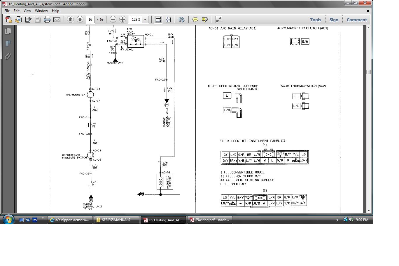
If you removed the symbols, most wiring diagrams would be impossible to read. Each symbol is a promise: “this part behaves like this in the circuit.” That is why two very different physical parts can share similar icons if their function is similar.
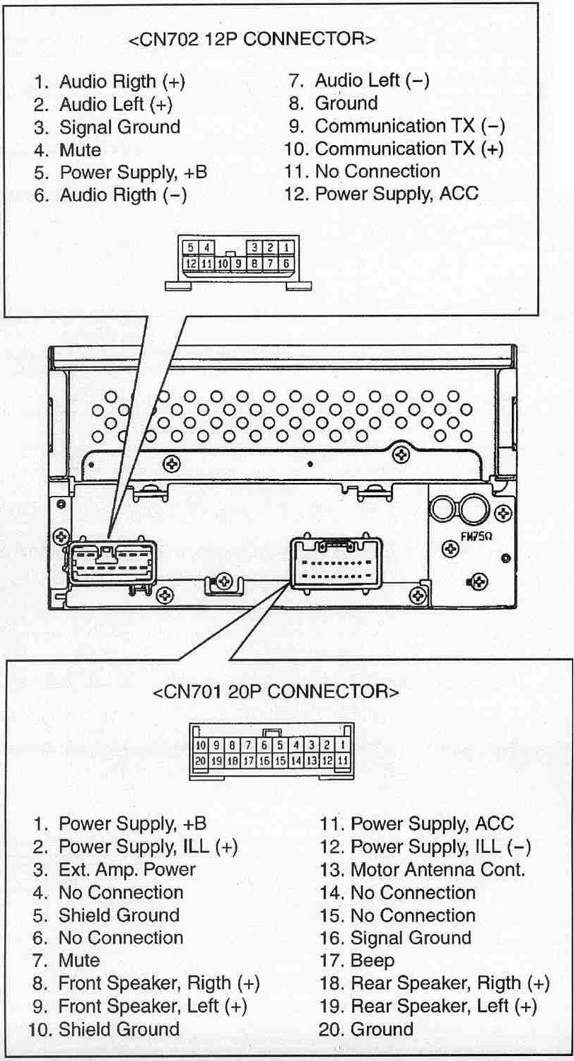
Abbreviations fill in operating mode and intent. Common markings include SIG IN, OUT, PWM CTRL, REF 5V, and N/O or N/C to show default switch position. You’ll often see SHLD to mark shielded cable for noise‑sensitive sensor lines in “Toyota Denso Radio Manual Wiring Diagram”.
Misreading even one tag can lead to the wrong test method and possible damage in Wiring Diagram. For that reason, experienced techs always cross‑check the abbreviation, symbol, and harness routing in 2026 before applying power. Maintaining notes and probe records tied to http://mydiagram.online and https://http://mydiagram.online/toyota-denso-radio-manual-wiring-diagram/MYDIAGRAM.ONLINE protects future diagnostics.
The combination of wire colors and gauges forms the language of every electrical circuit. {Each color provides identification for function — such as voltage supply, ground, or communication — while gauge defines how much current it can carry safely.|Colors serve as immediate fun...
Across Wiring Diagram, wire color and gauge conventions usually align with ISO 6722 and SAE J1128 to maintain compatibility between service manuals. {Red typically indicates battery voltage, black or brown ground, yellow ignition, ...
During repair or customization of “Toyota Denso Radio Manual Wiring Diagram”, technicians must maintain original wire color and cross-section according to factory data. {Substituting the wrong color can cause confusion for future technicians and violates quality assurance pol...

Power distribution is the foundation that keeps electrical systems operating safely and efficiently.
It controls energy delivery from the supply to every circuit, component, and actuator, ensuring steady flow.
A good distribution network ensures that each circuit in “Toyota Denso Radio Manual Wiring Diagram” receives the right voltage and current at all times.
Such design avoids overloads, voltage dips, and premature component fatigue.
In summary, it turns raw power into a stable, usable energy stream for all system parts.
Designing a proper distribution system starts with defining total power demand and branch allocation.
Fuses, connectors, and cables should match the system’s load current with an adequate safety factor.
Engineers in Wiring Diagram typically follow standards like ISO 16750, IEC 61000, and SAE J1113 to guarantee safety and performance.
Separate power and data lines to reduce interference and maintain circuit integrity.
Grounding locations should be marked, and fuse boxes must remain accessible for inspection.
Proper design ensures that “Toyota Denso Radio Manual Wiring Diagram” maintains operational stability even under maximum load or extreme conditions.
Once installed, the final phase involves testing and detailed documentation.
Technicians must test voltage levels, verify fuse ratings, and ensure resistance stays within limits.
Modifications during installation must be updated in drawings and digital records immediately.
All validation data and inspection images should be archived in http://mydiagram.online for future access.
Including the project year (2026) and related https://http://mydiagram.online/toyota-denso-radio-manual-wiring-diagram/MYDIAGRAM.ONLINE maintains traceable quality documentation.
Proper documentation ensures “Toyota Denso Radio Manual Wiring Diagram” stays reliable, easy to maintain, and compliant with standards.

It acts as the essential connection that stabilizes systems by linking them securely to the ground.
Grounding functions as a shield that controls excess current and protects from dangerous voltage fluctuations.
Without proper grounding, “Toyota Denso Radio Manual Wiring Diagram” may suffer from erratic voltage, electrical noise, or serious equipment damage.
Good grounding minimizes these risks by providing a defined, low-resistance path for current to return safely to the ground.
Across Wiring Diagram, grounding is a mandatory practice for maintaining reliable and safe electrical systems.
Effective grounding begins with strategic design and detailed preparation.
Engineers must analyze soil resistivity, current distribution, and environmental conditions before installation.
Each connection must be mechanically strong, corrosion-resistant, and securely bonded to the main grounding network.
In Wiring Diagram, international standards such as IEC 60364 and IEEE 142 provide comprehensive guidance for grounding design and maintenance.
Every grounding element must pass tests proving it can manage full fault current safely.
Through these grounding principles, “Toyota Denso Radio Manual Wiring Diagram” achieves reliability, efficiency, and operational security.
Routine testing and inspection are vital to verify that the grounding system continues to perform effectively.
Technicians should measure ground resistance, inspect connections, and record results for long-term analysis.
Any damaged or oxidized component must be cleaned, replaced, and retested immediately.
All inspection logs and test results must be documented and preserved for audit and traceability.
Testing schedules should include yearly verification or follow-ups after any electrical change.
By following scheduled inspections, “Toyota Denso Radio Manual Wiring Diagram” ensures reliable performance and compliance for years.

Toyota Denso Radio Manual Wiring Diagram Wiring Guide – Connector Index & Pinout 2026
Routine connector cleaning greatly improves long-term system reliability. {Dirt, oil, and oxidation can build up on terminals, increasing resistance and causing voltage drops.|Contamination inside connectors often leads to intermittent faults and sensor malfunctions.|A layer of corrosion or grime can disrupt even...
Always avoid using water or standard solvents that may damage seals or insulation. {For stubborn oxidation, a soft brush or lint-free swab can be used carefully on exposed metal surfaces.|Gently brushing corroded pins restores conductivity while maintaining plating integrity.|Never use abrasive materials that could scratch or ...
Ensure all seals and gaskets are properly seated once reconnected. Periodic cleaning keeps connector resistance low and ensures stable current transmission.

Toyota Denso Radio Manual Wiring Diagram – Sensor Inputs 2026
The Fuel Rail Pressure (FRP) sensor monitors fuel pressure within the fuel rail to ensure stable injection performance. {The ECU uses FRP input to adjust pump control, injector timing, and fuel trim.|Fuel pressure data enables automatic correction during load or temperature changes.|Stable FRP feedback ensures consistent engine po...
As pressure rises, the diaphragm inside the sensor deforms, altering resistance and voltage output. {A typical FRP sensor operates with a 5V reference and outputs between 0.5V (low pressure) and 4.5V (high pressure).|Voltage increases linearly as pressure builds up inside the fuel rail.|This direct feedback allows precise injector control for each cy...
A faulty FRP sensor can cause starting difficulty, poor acceleration, or rough idle. {Maintaining FRP sensor accuracy ensures safe pressure control and improved fuel economy.|Proper sensor calibration reduces risk of injector failure and unstable performance.|Understanding FRP feedback logic enhances fuel system diagnostics and reliabi...

Toyota Denso Radio Manual Wiring Diagram – Sensor Inputs 2026
In every electrical control network, sensor inputs serve as the key interface between machines and real-world data. {They convert real-world parameters such as temperature, pressure, or motion into electrical signals that computers can interpret.|Sensors transform physical changes into measurable voltage o...
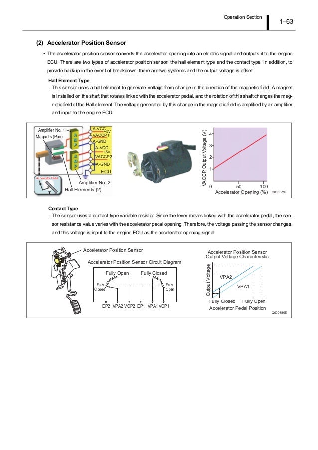
A typical sensor produces voltage, current, or digital pulses proportional to the measured parameter. {For instance, a throttle position sensor sends changing voltage values as the pedal moves.|Temperature sensors adjust resistance based on heat, while pressure sensors output corresponding voltage levels.|A speed sensor m...
Interpreting sensor signals allows the system to make real-time corrections and maintain performance. {Understanding sensor inputs enables technicians to identify faulty circuits, verify signal accuracy, and maintain system stability.|By mastering sensor logic, engineers can p...

Toyota Denso Radio Manual Wiring Diagram – Actuator Outputs Reference 2026
This system provides smoother acceleration, improved fuel economy, and better emissions control. {The ECU determines throttle position by processing data from accelerator pedal and engine sensors.|It commands a DC motor within the throttle body to open or close the valve precisely.|Feedback sensors report the actua...
These sensors monitor both commanded and actual valve angles for safety. The ECU continuously adjusts duty cycle to maintain desired air intake.
Technicians should perform adaptation resets after cleaning or replacement. Proper diagnosis and calibration enhance driveability and response.
Communication bus systems in Toyota Denso Radio Manual Wiring Diagram 2026 Wiring Diagram serve as the
coordinated digital backbone that links sensors, actuators, and
electronic control units into a synchronized data environment. Through
structured packet transmission, these networks maintain consistency
across powertrain, chassis, and body domains even under demanding
operating conditions such as thermal expansion, vibration, and
high-speed load transitions.
Modern platforms rely on a hierarchy of standards including CAN for
deterministic control, LIN for auxiliary functions, FlexRay for
high-stability timing loops, and Ethernet for high-bandwidth sensing.
Each protocol fulfills unique performance roles that enable safe
coordination of braking, torque management, climate control, and
driver-assistance features.
Communication failures may arise from impedance drift, connector
oxidation, EMI bursts, or degraded shielding, often manifesting as
intermittent sensor dropouts, delayed actuator behavior, or corrupted
frames. Diagnostics require voltage verification, termination checks,
and waveform analysis to isolate the failing segment.
Protection systems in Toyota Denso Radio Manual Wiring Diagram 2026 Wiring Diagram rely on fuses and relays
to form a controlled barrier between electrical loads and the vehicle’s
power distribution backbone. These elements react instantly to abnormal
current patterns, stopping excessive amperage before it cascades into
critical modules. By segmenting circuits into isolated branches, the
system protects sensors, control units, lighting, and auxiliary
equipment from thermal stress and wiring burnout.
Automotive fuses vary from micro types to high‑capacity cartridge
formats, each tailored to specific amperage tolerances and activation
speeds. Relays complement them by acting as electronically controlled
switches that manage high‑current operations such as cooling fans, fuel
systems, HVAC blowers, window motors, and ignition‑related loads. The
synergy between rapid fuse interruption and precision relay switching
establishes a controlled electrical environment across all driving
conditions.
Technicians often
diagnose issues by tracking inconsistent current delivery, noisy relay
actuation, unusual voltage fluctuations, or thermal discoloration on
fuse panels. Addressing these problems involves cleaning terminals,
reseating connectors, conditioning ground paths, and confirming load
consumption through controlled testing. Maintaining relay responsiveness
and fuse integrity ensures long‑term electrical stability.

Within modern automotive systems,
reference pads act as structured anchor locations for multimeter-guided
validation, enabling repeatable and consistent measurement sessions.
Their placement across sensor returns, control-module feeds, and
distribution junctions ensures that technicians can evaluate baseline
conditions without interference from adjacent circuits. This allows
diagnostic tools to interpret subsystem health with greater accuracy.
Technicians rely on these access nodes to conduct oscilloscope-driven
assessment, waveform pattern checks, and signal-shape verification
across multiple operational domains. By comparing known reference values
against observed readings, inconsistencies can quickly reveal poor
grounding, voltage imbalance, or early-stage conductor fatigue. These
cross-checks are essential when diagnosing sporadic faults that only
appear during thermal expansion cycles or variable-load driving
conditions.
Common issues identified through test point evaluation include voltage
fluctuation, unstable ground return, communication dropouts, and erratic
sensor baselines. These symptoms often arise from corrosion, damaged
conductors, poorly crimped terminals, or EMI contamination along
high-frequency lines. Proper analysis requires oscilloscope tracing,
continuity testing, and resistance indexing to compare expected values
with real-time data.

Measurement procedures for Toyota Denso Radio Manual Wiring Diagram 2026 Wiring Diagram begin with current
flow auditing to establish accurate diagnostic foundations. Technicians
validate stable reference points such as regulator outputs, ground
planes, and sensor baselines before proceeding with deeper analysis.
This ensures reliable interpretation of electrical behavior under
different load and temperature conditions.
Field evaluations often incorporate circuit
amperage validation, ensuring comprehensive monitoring of voltage
levels, signal shape, and communication timing. These measurements
reveal hidden failures such as intermittent drops, loose contacts, or
EMI-driven distortions.
Common measurement findings include fluctuating supply rails, irregular
ground returns, unstable sensor signals, and waveform distortion caused
by EMI contamination. Technicians use oscilloscopes, multimeters, and
load probes to isolate these anomalies with precision.

Troubleshooting for Toyota Denso Radio Manual Wiring Diagram 2026 Wiring Diagram begins with generalized
subsystem checks, ensuring the diagnostic process starts with clarity
and consistency. By checking basic system readiness, technicians avoid
deeper misinterpretations.
Technicians use scan-tool parameter correlation to narrow fault
origins. By validating electrical integrity and observing behavior under
controlled load, they identify abnormal deviations early.
Degraded shielding can allow external
electromagnetic bursts to distort communication lines. Shield continuity
checks and rewrapping harness segments mitigate the issue.

Common fault patterns in Toyota Denso Radio Manual Wiring Diagram 2026 Wiring Diagram frequently stem from
ground-loop conflicts within distributed control networks, a condition
that introduces irregular electrical behavior observable across multiple
subsystems. Early-stage symptoms are often subtle, manifesting as small
deviations in baseline readings or intermittent inconsistencies that
disappear as quickly as they appear. Technicians must therefore begin
diagnostics with broad-spectrum inspection, ensuring that fundamental
supply and return conditions are stable before interpreting more complex
indicators.
When examining faults tied to ground-loop conflicts within distributed
control networks, technicians often observe fluctuations that correlate
with engine heat, module activation cycles, or environmental humidity.
These conditions can cause reference rails to drift or sensor outputs to
lose linearity, leading to miscommunication between control units. A
structured diagnostic workflow involves comparing real-time readings to
known-good values, replicating environmental conditions, and isolating
behavior changes under controlled load simulations.
Left unresolved, ground-loop conflicts within
distributed control networks may cause cascading failures as modules
attempt to compensate for distorted data streams. This can trigger false
DTCs, unpredictable load behavior, delayed actuator response, and even
safety-feature interruptions. Comprehensive analysis requires reviewing
subsystem interaction maps, recreating stress conditions, and validating
each reference point’s consistency under both static and dynamic
operating states.

Maintenance and best practices for Toyota Denso Radio Manual Wiring Diagram 2026 Wiring Diagram place
strong emphasis on ground-loop avoidance best practices, ensuring that
electrical reliability remains consistent across all operating
conditions. Technicians begin by examining the harness environment,
verifying routing paths, and confirming that insulation remains intact.
This foundational approach prevents intermittent issues commonly
triggered by heat, vibration, or environmental contamination.
Technicians
analyzing ground-loop avoidance best practices typically monitor
connector alignment, evaluate oxidation levels, and inspect wiring for
subtle deformations caused by prolonged thermal exposure. Protective
dielectric compounds and proper routing practices further contribute to
stable electrical pathways that resist mechanical stress and
environmental impact.
Issues associated with ground-loop avoidance best practices frequently
arise from overlooked early wear signs, such as minor contact resistance
increases or softening of insulation under prolonged heat. Regular
maintenance cycles—including resistance indexing, pressure testing, and
moisture-barrier reinforcement—ensure that electrical pathways remain
dependable and free from hidden vulnerabilities.
In many vehicle platforms,
the appendix operates as a universal alignment guide centered on
continuity and resistance benchmark tables, helping technicians maintain
consistency when analyzing circuit diagrams or performing diagnostic
routines. This reference section prevents confusion caused by
overlapping naming systems or inconsistent labeling between subsystems,
thereby establishing a unified technical language.
Documentation related to continuity and resistance benchmark tables
frequently includes structured tables, indexing lists, and lookup
summaries that reduce the need to cross‑reference multiple sources
during system evaluation. These entries typically describe connector
types, circuit categories, subsystem identifiers, and signal behavior
definitions. By keeping these details accessible, technicians can
accelerate the interpretation of wiring diagrams and troubleshoot with
greater accuracy.
Comprehensive references for continuity and resistance benchmark tables
also support long‑term documentation quality by ensuring uniform
terminology across service manuals, schematics, and diagnostic tools.
When updates occur—whether due to new sensors, revised standards, or
subsystem redesigns—the appendix remains the authoritative source for
maintaining alignment between engineering documentation and real‑world
service practices.
Signal‑integrity evaluation must account for the influence of
EMC-driven desynchronization between control units, as even minor
waveform displacement can compromise subsystem coordination. These
variances affect module timing, digital pulse shape, and analog
accuracy, underscoring the need for early-stage waveform sampling before
deeper EMC diagnostics.
When EMC-driven desynchronization between control units occurs, signals
may experience phase delays, amplitude decay, or transient ringing
depending on harness composition and environmental exposure. Technicians
must review waveform transitions under varying thermal, load, and EMI
conditions. Tools such as high‑bandwidth oscilloscopes and frequency
analyzers reveal distortion patterns that remain hidden during static
measurements.
Left uncorrected, EMC-driven desynchronization between control units
can progress into widespread communication degradation, module
desynchronization, or unstable sensor logic. Technicians must verify
shielding continuity, examine grounding symmetry, analyze differential
paths, and validate signal behavior across environmental extremes. Such
comprehensive evaluation ensures repairs address root EMC
vulnerabilities rather than surface‑level symptoms.

Deep technical assessment of EMC interactions must account for
EMC coupling through asymmetrical grounding paths, as the resulting
disturbances can propagate across wiring networks and disrupt
timing‑critical communication. These disruptions often appear
sporadically, making early waveform sampling essential to characterize
the extent of electromagnetic influence across multiple operational
states.
Systems experiencing EMC coupling through
asymmetrical grounding paths frequently show inconsistencies during fast
state transitions such as ignition sequencing, data bus arbitration, or
actuator modulation. These inconsistencies originate from embedded EMC
interactions that vary with harness geometry, grounding quality, and
cable impedance. Multi‑stage capture techniques help isolate the root
interaction layer.
If left unresolved, EMC coupling through asymmetrical
grounding paths may trigger cascading disruptions including frame
corruption, false sensor readings, and irregular module coordination.
Effective countermeasures include controlled grounding, noise‑filter
deployment, re‑termination of critical paths, and restructuring of cable
routing to minimize electromagnetic coupling.
A comprehensive
assessment of waveform stability requires understanding the effects of
environmental RF flooding diminishing differential-pair coherence, a
factor capable of reshaping digital and analog signal profiles in subtle
yet impactful ways. This initial analysis phase helps technicians
identify whether distortions originate from physical harness geometry,
electromagnetic ingress, or internal module reference instability.
Systems experiencing environmental RF flooding diminishing
differential-pair coherence often show dynamic fluctuations during
transitions such as relay switching, injector activation, or alternator
charging ramps. These transitions inject complex disturbances into
shared wiring paths, making it essential to perform frequency-domain
inspection, spectral decomposition, and transient-load waveform sampling
to fully characterize the EMC interaction.
Prolonged exposure to environmental RF flooding diminishing
differential-pair coherence may result in cumulative timing drift,
erratic communication retries, or persistent sensor inconsistencies.
Mitigation strategies include rebalancing harness impedance, reinforcing
shielding layers, deploying targeted EMI filters, optimizing grounding
topology, and refining cable routing to minimize exposure to EMC
hotspots. These measures restore signal clarity and long-term subsystem
reliability.
Evaluating advanced signal‑integrity interactions involves
examining the influence of dynamic reference collapse triggered by
simultaneous module sync, a phenomenon capable of inducing significant
waveform displacement. These disruptions often develop gradually,
becoming noticeable only when communication reliability begins to drift
or subsystem timing loses coherence.
Systems experiencing
dynamic reference collapse triggered by simultaneous module sync
frequently show instability during high‑demand operational windows, such
as engine load surges, rapid relay switching, or simultaneous
communication bursts. These events amplify embedded EMI vectors, making
spectral analysis essential for identifying the root interference mode.
Long‑term exposure to dynamic reference collapse triggered by
simultaneous module sync can create cascading waveform degradation,
arbitration failures, module desynchronization, or persistent sensor
inconsistency. Corrective strategies include impedance tuning, shielding
reinforcement, ground‑path rebalancing, and reconfiguration of sensitive
routing segments. These adjustments restore predictable system behavior
under varied EMI conditions.

In-depth signal integrity analysis requires
understanding how multi-layer electromagnetic field superposition across
dense harness zones influences propagation across mixed-frequency
network paths. These distortions may remain hidden during low-load
conditions, only becoming evident when multiple modules operate
simultaneously or when thermal boundaries shift.
Systems exposed to
multi-layer electromagnetic field superposition across dense harness
zones often show instability during rapid subsystem transitions. This
instability results from interference coupling into sensitive wiring
paths, causing skew, jitter, or frame corruption. Multi-domain waveform
capture reveals how these disturbances propagate and interact.
Long-term exposure to multi-layer electromagnetic field superposition
across dense harness zones can lead to cumulative communication
degradation, sporadic module resets, arbitration errors, and
inconsistent sensor behavior. Technicians mitigate these issues through
grounding rebalancing, shielding reinforcement, optimized routing,
precision termination, and strategic filtering tailored to affected
frequency bands.

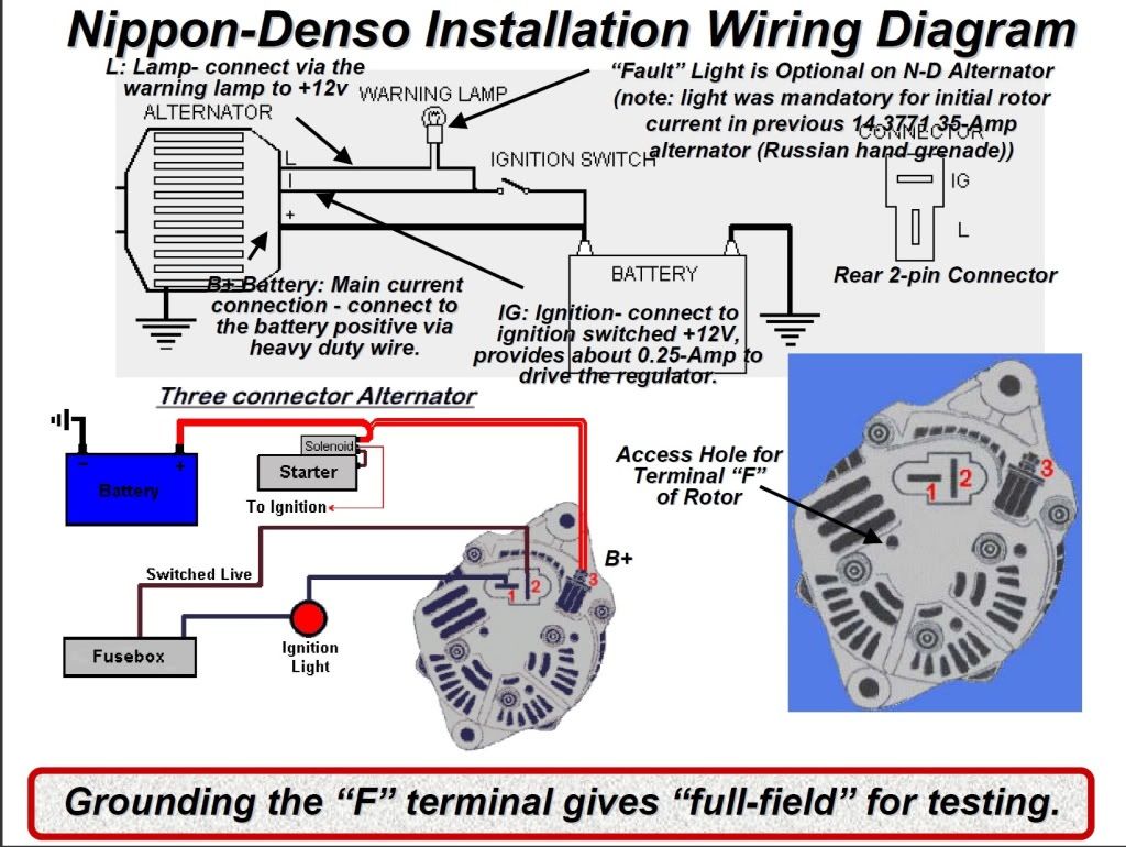
This section on STARTING/CHARGING explains how these principles apply to denso radio manual wiring diagram systems. Focus on repeatable tests, clear documentation, and safe handling. Keep a simple log: symptom → test → reading → decision → fix.

The
engineering process behind Harness Layout Variant #2 evaluates how
electrical separation rules for hybrid high-voltage and low-voltage
harnesses interacts with subsystem density, mounting geometry, EMI
exposure, and serviceability. This foundational planning ensures clean
routing paths and consistent system behavior over the vehicle’s full
operating life.
In real-world conditions, electrical
separation rules for hybrid high-voltage and low-voltage harnesses
determines the durability of the harness against temperature cycles,
motion-induced stress, and subsystem interference. Careful arrangement
of connectors, bundling layers, and anti-chafe supports helps maintain
reliable performance even in high-demand chassis zones.
Managing electrical separation rules for hybrid high-voltage and
low-voltage harnesses effectively results in improved robustness,
simplified maintenance, and enhanced overall system stability. Engineers
apply isolation rules, structural reinforcement, and optimized routing
logic to produce a layout capable of sustaining long-term operational
loads.
Harness Layout Variant #3 for Toyota Denso Radio Manual Wiring Diagram 2026 Wiring Diagram focuses on
signal-safe routing overlays across hybrid structural panels, an
essential structural and functional element that affects reliability
across multiple vehicle zones. Modern platforms require routing that
accommodates mechanical constraints while sustaining consistent
electrical behavior and long-term durability.
During refinement, signal-safe routing overlays across hybrid
structural panels can impact vibration resistance, shielding
effectiveness, ground continuity, and stress distribution along key
segments. Designers analyze bundle thickness, elevation shifts,
structural transitions, and separation from high‑interference components
to optimize both mechanical and electrical performance.
If not addressed,
signal-safe routing overlays across hybrid structural panels may lead to
premature insulation wear, abrasion hotspots, intermittent electrical
noise, or connector fatigue. Balanced tensioning, routing symmetry, and
strategic material selection significantly mitigate these risks across
all major vehicle subsystems.

Harness Layout Variant #4 for Toyota Denso Radio Manual Wiring Diagram 2026 Wiring Diagram emphasizes instrument-panel low-profile channels for
compact assemblies, combining mechanical and electrical considerations to maintain cable stability across
multiple vehicle zones. Early planning defines routing elevation, clearance from heat sources, and anchoring
points so each branch can absorb vibration and thermal expansion without overstressing connectors.
During refinement, instrument-panel low-profile channels for compact assemblies
influences grommet placement, tie-point spacing, and bend-radius decisions. These parameters determine whether
the harness can endure heat cycles, structural motion, and chassis vibration. Power–data separation rules,
ground-return alignment, and shielding-zone allocation help suppress interference without hindering
manufacturability.
If overlooked, instrument-panel low-profile channels for
compact assemblies may lead to insulation wear, loose connections, or intermittent signal faults caused by
chafing. Solutions include anchor repositioning, spacing corrections, added shielding, and branch
restructuring to shorten paths and improve long-term serviceability.

The initial stage of Diagnostic
Flowchart #1 emphasizes structured relay and fuse validation within fault cascades, ensuring that the most
foundational electrical references are validated before branching into deeper subsystem evaluation. This
reduces misdirection caused by surface‑level symptoms. As
diagnostics progress, structured relay and fuse validation within fault cascades becomes a critical branch
factor influencing decisions relating to grounding integrity, power sequencing, and network communication
paths. This structured logic ensures accuracy even when symptoms appear scattered. A complete validation
cycle ensures structured relay and fuse validation within fault cascades is confirmed across all operational
states. Documenting each decision point creates traceability, enabling faster future diagnostics and reducing
the chance of repeat failures.

The initial phase of Diagnostic Flowchart #2
emphasizes cross-domain diagnostic segmentation for hybrid circuits, ensuring that technicians validate
foundational electrical relationships before evaluating deeper subsystem interactions. This prevents
diagnostic drift and reduces unnecessary component replacements. Throughout the flowchart, cross-domain diagnostic segmentation for hybrid circuits interacts with
verification procedures involving reference stability, module synchronization, and relay or fuse behavior.
Each decision point eliminates entire categories of possible failures, allowing the technician to converge
toward root cause faster. Completing the flow ensures that cross-domain diagnostic segmentation for hybrid
circuits is validated under multiple operating conditions, reducing the likelihood of recurring issues. The
resulting diagnostic trail provides traceable documentation that improves future troubleshooting accuracy.

The first branch of Diagnostic Flowchart #3 prioritizes progressive ground‑loop
elimination across chassis segments, ensuring foundational stability is confirmed before deeper subsystem
exploration. This prevents misdirection caused by intermittent or misleading electrical behavior. As the
flowchart progresses, progressive ground‑loop elimination across chassis segments defines how mid‑stage
decisions are segmented. Technicians sequentially eliminate power, ground, communication, and actuation
domains while interpreting timing shifts, signal drift, or misalignment across related circuits. Once progressive ground‑loop elimination across chassis
segments is fully evaluated across multiple load states, the technician can confirm or dismiss entire fault
categories. This structured approach enhances long‑term reliability and reduces repeat troubleshooting
visits.

Diagnostic Flowchart #4 for Toyota Denso Radio Manual Wiring Diagram 2026 Wiring Diagram focuses on PWM‑signal distortion analysis across
actuator paths, laying the foundation for a structured fault‑isolation path that eliminates guesswork and
reduces unnecessary component swapping. The first stage examines core references, voltage stability, and
baseline communication health to determine whether the issue originates in the primary network layer or in a
secondary subsystem. Technicians follow a branched decision flow that evaluates signal symmetry, grounding
patterns, and frame stability before advancing into deeper diagnostic layers. As the evaluation continues, PWM‑signal distortion analysis across
actuator paths becomes the controlling factor for mid‑level branch decisions. This includes correlating
waveform alignment, identifying momentary desync signatures, and interpreting module wake‑timing conflicts. By
dividing the diagnostic pathway into focused electrical domains—power delivery, grounding integrity,
communication architecture, and actuator response—the flowchart ensures that each stage removes entire
categories of faults with minimal overlap. This structured segmentation accelerates troubleshooting and
increases diagnostic precision. The final stage ensures that
PWM‑signal distortion analysis across actuator paths is validated under multiple operating conditions,
including thermal stress, load spikes, vibration, and state transitions. These controlled stress points help
reveal hidden instabilities that may not appear during static testing. Completing all verification nodes
ensures long‑term stability, reducing the likelihood of recurring issues and enabling technicians to document
clear, repeatable steps for future diagnostics.

Case Study #1 for Toyota Denso Radio Manual Wiring Diagram 2026 Wiring Diagram examines a real‑world failure involving gateway communication
collapse from over‑current heating. The issue first appeared as an intermittent symptom that did not trigger a
consistent fault code, causing technicians to suspect unrelated components. Early observations highlighted
irregular electrical behavior, such as momentary signal distortion, delayed module responses, or fluctuating
reference values. These symptoms tended to surface under specific thermal, vibration, or load conditions,
making replication difficult during static diagnostic tests. Further investigation into gateway communication
collapse from over‑current heating required systematic measurement across power distribution paths, grounding
nodes, and communication channels. Technicians used targeted diagnostic flowcharts to isolate variables such
as voltage drop, EMI exposure, timing skew, and subsystem desynchronization. By reproducing the fault under
controlled conditions—applying heat, inducing vibration, or simulating high load—they identified the precise
moment the failure manifested. This structured process eliminated multiple potential contributors, narrowing
the fault domain to a specific harness segment, component group, or module logic pathway. The confirmed cause
tied to gateway communication collapse from over‑current heating allowed technicians to implement the correct
repair, whether through component replacement, harness restoration, recalibration, or module reprogramming.
After corrective action, the system was subjected to repeated verification cycles to ensure long‑term
stability under all operating conditions. Documenting the failure pattern and diagnostic sequence provided
valuable reference material for similar future cases, reducing diagnostic time and preventing unnecessary part
replacement.
Case Study #2 for Toyota Denso Radio Manual Wiring Diagram 2026 Wiring Diagram examines a real‑world failure involving transmission‑control desync
driven by ripple‑heavy alternator output. The issue presented itself with intermittent symptoms that varied
depending on temperature, load, or vehicle motion. Technicians initially observed irregular system responses,
inconsistent sensor readings, or sporadic communication drops. Because the symptoms did not follow a
predictable pattern, early attempts at replication were unsuccessful, leading to misleading assumptions about
unrelated subsystems. A detailed investigation into transmission‑control desync driven by ripple‑heavy
alternator output required structured diagnostic branching that isolated power delivery, ground stability,
communication timing, and sensor integrity. Using controlled diagnostic tools, technicians applied thermal
load, vibration, and staged electrical demand to recreate the failure in a measurable environment. Progressive
elimination of subsystem groups—ECUs, harness segments, reference points, and actuator pathways—helped reveal
how the failure manifested only under specific operating thresholds. This systematic breakdown prevented
misdiagnosis and reduced unnecessary component swaps. Once the cause linked to transmission‑control desync
driven by ripple‑heavy alternator output was confirmed, the corrective action involved either reconditioning
the harness, replacing the affected component, reprogramming module firmware, or adjusting calibration
parameters. Post‑repair validation cycles were performed under varied conditions to ensure long‑term
reliability and prevent future recurrence. Documentation of the failure characteristics, diagnostic sequence,
and final resolution now serves as a reference for addressing similar complex faults more efficiently.

Case Study #3 for Toyota Denso Radio Manual Wiring Diagram 2026 Wiring Diagram focuses on a real‑world failure involving battery‑supply
fluctuation causing cascading multi‑module instability. Technicians first observed erratic system behavior,
including fluctuating sensor values, delayed control responses, and sporadic communication warnings. These
symptoms appeared inconsistently, often only under specific temperature, load, or vibration conditions. Early
troubleshooting attempts failed to replicate the issue reliably, creating the impression of multiple unrelated
subsystem faults rather than a single root cause. To investigate battery‑supply fluctuation causing cascading
multi‑module instability, a structured diagnostic approach was essential. Technicians conducted staged power
and ground validation, followed by controlled stress testing that included thermal loading, vibration
simulation, and alternating electrical demand. This method helped reveal the precise operational threshold at
which the failure manifested. By isolating system domains—communication networks, power rails, grounding
nodes, and actuator pathways—the diagnostic team progressively eliminated misleading symptoms and narrowed the
problem to a specific failure mechanism. After identifying the underlying cause tied to battery‑supply
fluctuation causing cascading multi‑module instability, technicians carried out targeted corrective actions
such as replacing compromised components, restoring harness integrity, updating ECU firmware, or recalibrating
affected subsystems. Post‑repair validation cycles confirmed stable performance across all operating
conditions. The documented diagnostic path and resolution now serve as a repeatable reference for addressing
similar failures with greater speed and accuracy.

Case Study #4 for Toyota Denso Radio Manual Wiring Diagram 2026 Wiring Diagram examines a high‑complexity real‑world failure involving air‑fuel
control deviation caused by MAP sensor saturation. The issue manifested across multiple subsystems
simultaneously, creating an array of misleading symptoms ranging from inconsistent module responses to
distorted sensor feedback and intermittent communication warnings. Initial diagnostics were inconclusive due
to the fault’s dependency on vibration, thermal shifts, or rapid load changes. These fluctuating conditions
allowed the failure to remain dormant during static testing, pushing technicians to explore deeper system
interactions that extended beyond conventional troubleshooting frameworks. To investigate air‑fuel control
deviation caused by MAP sensor saturation, technicians implemented a layered diagnostic workflow combining
power‑rail monitoring, ground‑path validation, EMI tracing, and logic‑layer analysis. Stress tests were
applied in controlled sequences to recreate the precise environment in which the instability surfaced—often
requiring synchronized heat, vibration, and electrical load modulation. By isolating communication domains,
verifying timing thresholds, and comparing analog sensor behavior under dynamic conditions, the diagnostic
team uncovered subtle inconsistencies that pointed toward deeper system‑level interactions rather than
isolated component faults. After confirming the root mechanism tied to air‑fuel control deviation caused by
MAP sensor saturation, corrective action involved component replacement, harness reconditioning, ground‑plane
reinforcement, or ECU firmware restructuring depending on the failure’s nature. Technicians performed
post‑repair endurance tests that included repeated thermal cycling, vibration exposure, and electrical stress
to guarantee long‑term system stability. Thorough documentation of the analysis method, failure pattern, and
final resolution now serves as a highly valuable reference for identifying and mitigating similar
high‑complexity failures in the future.

Case Study #5 for Toyota Denso Radio Manual Wiring Diagram 2026 Wiring Diagram investigates a complex real‑world failure involving alternator
ripple spread destabilizing module reference voltages. The issue initially presented as an inconsistent
mixture of delayed system reactions, irregular sensor values, and sporadic communication disruptions. These
events tended to appear under dynamic operational conditions—such as elevated temperatures, sudden load
transitions, or mechanical vibration—which made early replication attempts unreliable. Technicians encountered
symptoms occurring across multiple modules simultaneously, suggesting a deeper systemic interaction rather
than a single isolated component failure. During the investigation of alternator ripple spread destabilizing
module reference voltages, a multi‑layered diagnostic workflow was deployed. Technicians performed sequential
power‑rail mapping, ground‑plane verification, and high‑frequency noise tracing to detect hidden
instabilities. Controlled stress testing—including targeted heat application, induced vibration, and variable
load modulation—was carried out to reproduce the failure consistently. The team methodically isolated
subsystem domains such as communication networks, analog sensor paths, actuator control logic, and module
synchronization timing. This progressive elimination approach identified critical operational thresholds where
the failure reliably emerged. After determining the underlying mechanism tied to alternator ripple spread
destabilizing module reference voltages, technicians carried out corrective actions that ranged from harness
reconditioning and connector reinforcement to firmware restructuring and recalibration of affected modules.
Post‑repair validation involved repeated cycles of vibration, thermal stress, and voltage fluctuation to
ensure long‑term stability and eliminate the possibility of recurrence. The documented resolution pathway now
serves as an advanced reference model for diagnosing similarly complex failures across modern vehicle
platforms.
Case Study #6 for Toyota Denso Radio Manual Wiring Diagram 2026 Wiring Diagram examines a complex real‑world failure involving gateway arbitration
stalls during dense multi‑channel CAN traffic. Symptoms emerged irregularly, with clustered faults appearing
across unrelated modules, giving the impression of multiple simultaneous subsystem failures. These
irregularities depended strongly on vibration, temperature shifts, or abrupt electrical load changes, making
the issue difficult to reproduce during initial diagnostic attempts. Technicians noted inconsistent sensor
feedback, communication delays, and momentary power‑rail fluctuations that persisted without generating
definitive fault codes. The investigation into gateway arbitration stalls during dense multi‑channel CAN
traffic required a multi‑layer diagnostic strategy combining signal‑path tracing, ground stability assessment,
and high‑frequency noise evaluation. Technicians executed controlled stress tests—including thermal cycling,
vibration induction, and staged electrical loading—to reveal the exact thresholds at which the fault
manifested. Using structured elimination across harness segments, module clusters, and reference nodes, they
isolated subtle timing deviations, analog distortions, or communication desynchronization that pointed toward
a deeper systemic failure mechanism rather than isolated component malfunction. Once gateway arbitration
stalls during dense multi‑channel CAN traffic was identified as the root failure mechanism, targeted
corrective measures were implemented. These included harness reinforcement, connector replacement, firmware
restructuring, recalibration of key modules, or ground‑path reconfiguration depending on the nature of the
instability. Post‑repair endurance runs with repeated vibration, heat cycles, and voltage stress ensured
long‑term reliability. Documentation of the diagnostic sequence and recovery pathway now provides a vital
reference for detecting and resolving similarly complex failures more efficiently in future service
operations.
Hands‑On Lab #1 for Toyota Denso Radio Manual Wiring Diagram 2026 Wiring Diagram focuses on HV/LV isolation verification using differential
probing. This exercise teaches technicians how to perform structured diagnostic measurements using
multimeters, oscilloscopes, current probes, and differential tools. The initial phase emphasizes establishing
a stable baseline by checking reference voltages, verifying continuity, and confirming ground integrity. These
foundational steps ensure that subsequent measurements reflect true system behavior rather than secondary
anomalies introduced by poor probing technique or unstable electrical conditions. During the measurement
routine for HV/LV isolation verification using differential probing, technicians analyze dynamic behavior by
applying controlled load, capturing waveform transitions, and monitoring subsystem responses. This includes
observing timing shifts, duty‑cycle changes, ripple patterns, or communication irregularities. By replicating
real operating conditions—thermal changes, vibration, or electrical demand spikes—technicians gain insight
into how the system behaves under stress. This approach allows deeper interpretation of patterns that static
readings cannot reveal. After completing the procedure for HV/LV isolation verification using differential
probing, results are documented with precise measurement values, waveform captures, and interpretation notes.
Technicians compare the observed data with known good references to determine whether performance falls within
acceptable thresholds. The collected information not only confirms system health but also builds long‑term
diagnostic proficiency by helping technicians recognize early indicators of failure and understand how small
variations can evolve into larger issues.
Hands‑On Lab #2 for Toyota Denso Radio Manual Wiring Diagram 2026 Wiring Diagram focuses on thermal drift measurement in manifold pressure
sensors. This practical exercise expands technician measurement skills by emphasizing accurate probing
technique, stable reference validation, and controlled test‑environment setup. Establishing baseline
readings—such as reference ground, regulated voltage output, and static waveform characteristics—is essential
before any dynamic testing occurs. These foundational checks prevent misinterpretation caused by poor tool
placement, floating grounds, or unstable measurement conditions. During the procedure for thermal drift
measurement in manifold pressure sensors, technicians simulate operating conditions using thermal stress,
vibration input, and staged subsystem loading. Dynamic measurements reveal timing inconsistencies, amplitude
drift, duty‑cycle changes, communication irregularities, or nonlinear sensor behavior. Oscilloscopes, current
probes, and differential meters are used to capture high‑resolution waveform data, enabling technicians to
identify subtle deviations that static multimeter readings cannot detect. Emphasis is placed on interpreting
waveform shape, slope, ripple components, and synchronization accuracy across interacting modules. After
completing the measurement routine for thermal drift measurement in manifold pressure sensors, technicians
document quantitative findings—including waveform captures, voltage ranges, timing intervals, and noise
signatures. The recorded results are compared to known‑good references to determine subsystem health and
detect early‑stage degradation. This structured approach not only builds diagnostic proficiency but also
enhances a technician’s ability to predict emerging faults before they manifest as critical failures,
strengthening long‑term reliability of the entire system.

Hands‑On Lab #3 for Toyota Denso Radio Manual Wiring Diagram 2026 Wiring Diagram focuses on CAN transceiver edge‑rate evaluation using
differential probing. This exercise trains technicians to establish accurate baseline measurements before
introducing dynamic stress. Initial steps include validating reference grounds, confirming supply‑rail
stability, and ensuring probing accuracy. These fundamentals prevent distorted readings and help ensure that
waveform captures or voltage measurements reflect true electrical behavior rather than artifacts caused by
improper setup or tool noise. During the diagnostic routine for CAN transceiver edge‑rate evaluation using
differential probing, technicians apply controlled environmental adjustments such as thermal cycling,
vibration, electrical loading, and communication traffic modulation. These dynamic inputs help expose timing
drift, ripple growth, duty‑cycle deviations, analog‑signal distortion, or module synchronization errors.
Oscilloscopes, clamp meters, and differential probes are used extensively to capture transitional data that
cannot be observed with static measurements alone. After completing the measurement sequence for CAN
transceiver edge‑rate evaluation using differential probing, technicians document waveform characteristics,
voltage ranges, current behavior, communication timing variations, and noise patterns. Comparison with
known‑good datasets allows early detection of performance anomalies and marginal conditions. This structured
measurement methodology strengthens diagnostic confidence and enables technicians to identify subtle
degradation before it becomes a critical operational failure.

Hands‑On Lab #4 for Toyota Denso Radio Manual Wiring Diagram 2026 Wiring Diagram focuses on mass airflow sensor transient response measurement.
This laboratory exercise builds on prior modules by emphasizing deeper measurement accuracy, environment
control, and test‑condition replication. Technicians begin by validating stable reference grounds, confirming
regulated supply integrity, and preparing measurement tools such as oscilloscopes, current probes, and
high‑bandwidth differential probes. Establishing clean baselines ensures that subsequent waveform analysis is
meaningful and not influenced by tool noise or ground drift. During the measurement procedure for mass
airflow sensor transient response measurement, technicians introduce dynamic variations including staged
electrical loading, thermal cycling, vibration input, or communication‑bus saturation. These conditions reveal
real‑time behaviors such as timing drift, amplitude instability, duty‑cycle deviation, ripple formation, or
synchronization loss between interacting modules. High‑resolution waveform capture enables technicians to
observe subtle waveform features—slew rate, edge deformation, overshoot, undershoot, noise bursts, and
harmonic artifacts. Upon completing the assessment for mass airflow sensor transient response measurement,
all findings are documented with waveform snapshots, quantitative measurements, and diagnostic
interpretations. Comparing collected data with verified reference signatures helps identify early‑stage
degradation, marginal component performance, and hidden instability trends. This rigorous measurement
framework strengthens diagnostic precision and ensures that technicians can detect complex electrical issues
long before they evolve into system‑wide failures.
Hands‑On Lab #5 for Toyota Denso Radio Manual Wiring Diagram 2026 Wiring Diagram focuses on module wake‑sequence current‑profile measurement. The
session begins with establishing stable measurement baselines by validating grounding integrity, confirming
supply‑rail stability, and ensuring probe calibration. These steps prevent erroneous readings and ensure that
all waveform captures accurately reflect subsystem behavior. High‑accuracy tools such as oscilloscopes, clamp
meters, and differential probes are prepared to avoid ground‑loop artifacts or measurement noise. During the
procedure for module wake‑sequence current‑profile measurement, technicians introduce dynamic test conditions
such as controlled load spikes, thermal cycling, vibration, and communication saturation. These deliberate
stresses expose real‑time effects like timing jitter, duty‑cycle deformation, signal‑edge distortion, ripple
growth, and cross‑module synchronization drift. High‑resolution waveform captures allow technicians to
identify anomalies that static tests cannot reveal, such as harmonic noise, high‑frequency interference, or
momentary dropouts in communication signals. After completing all measurements for module wake‑sequence
current‑profile measurement, technicians document voltage ranges, timing intervals, waveform shapes, noise
signatures, and current‑draw curves. These results are compared against known‑good references to identify
early‑stage degradation or marginal component behavior. Through this structured measurement framework,
technicians strengthen diagnostic accuracy and develop long‑term proficiency in detecting subtle trends that
could lead to future system failures.

Hands‑On Lab #6 for Toyota Denso Radio Manual Wiring Diagram 2026 Wiring Diagram focuses on injector hold‑current decay behavior under thermal
stress. This advanced laboratory module strengthens technician capability in capturing high‑accuracy
diagnostic measurements. The session begins with baseline validation of ground reference integrity, regulated
supply behavior, and probe calibration. Ensuring noise‑free, stable baselines prevents waveform distortion and
guarantees that all readings reflect genuine subsystem behavior rather than tool‑induced artifacts or
grounding errors. Technicians then apply controlled environmental modulation such as thermal shocks,
vibration exposure, staged load cycling, and communication traffic saturation. These dynamic conditions reveal
subtle faults including timing jitter, duty‑cycle deformation, amplitude fluctuation, edge‑rate distortion,
harmonic buildup, ripple amplification, and module synchronization drift. High‑bandwidth oscilloscopes,
differential probes, and current clamps are used to capture transient behaviors invisible to static multimeter
measurements. Following completion of the measurement routine for injector hold‑current decay behavior under
thermal stress, technicians document waveform shapes, voltage windows, timing offsets, noise signatures, and
current patterns. Results are compared against validated reference datasets to detect early‑stage degradation
or marginal component behavior. By mastering this structured diagnostic framework, technicians build long‑term
proficiency and can identify complex electrical instabilities before they lead to full system failure.
Checklist & Form #1 for Toyota Denso Radio Manual Wiring Diagram 2026 Wiring Diagram focuses on PWM actuator functional verification checklist.
This verification document provides a structured method for ensuring electrical and electronic subsystems meet
required performance standards. Technicians begin by confirming baseline conditions such as stable reference
grounds, regulated voltage supplies, and proper connector engagement. Establishing these baselines prevents
false readings and ensures all subsequent measurements accurately reflect system behavior. During completion
of this form for PWM actuator functional verification checklist, technicians evaluate subsystem performance
under both static and dynamic conditions. This includes validating signal integrity, monitoring voltage or
current drift, assessing noise susceptibility, and confirming communication stability across modules.
Checkpoints guide technicians through critical inspection areas—sensor accuracy, actuator responsiveness, bus
timing, harness quality, and module synchronization—ensuring each element is validated thoroughly using
industry‑standard measurement practices. After filling out the checklist for PWM actuator functional
verification checklist, all results are documented, interpreted, and compared against known‑good reference
values. This structured documentation supports long‑term reliability tracking, facilitates early detection of
emerging issues, and strengthens overall system quality. The completed form becomes part of the
quality‑assurance record, ensuring compliance with technical standards and providing traceability for future
diagnostics.
Checklist & Form #2 for Toyota Denso Radio Manual Wiring Diagram 2026 Wiring Diagram focuses on fuse/relay operational reliability evaluation
sheet. This structured verification tool guides technicians through a comprehensive evaluation of electrical
system readiness. The process begins by validating baseline electrical conditions such as stable ground
references, regulated supply integrity, and secure connector engagement. Establishing these fundamentals
ensures that all subsequent diagnostic readings reflect true subsystem behavior rather than interference from
setup or tooling issues. While completing this form for fuse/relay operational reliability evaluation sheet,
technicians examine subsystem performance across both static and dynamic conditions. Evaluation tasks include
verifying signal consistency, assessing noise susceptibility, monitoring thermal drift effects, checking
communication timing accuracy, and confirming actuator responsiveness. Each checkpoint guides the technician
through critical areas that contribute to overall system reliability, helping ensure that performance remains
within specification even during operational stress. After documenting all required fields for fuse/relay
operational reliability evaluation sheet, technicians interpret recorded measurements and compare them against
validated reference datasets. This documentation provides traceability, supports early detection of marginal
conditions, and strengthens long‑term quality control. The completed checklist forms part of the official
audit trail and contributes directly to maintaining electrical‑system reliability across the vehicle platform.
Checklist & Form #3 for Toyota Denso Radio Manual Wiring Diagram 2026 Wiring Diagram covers ECU diagnostic readiness verification checklist. This
verification document ensures that every subsystem meets electrical and operational requirements before final
approval. Technicians begin by validating fundamental conditions such as regulated supply voltage, stable
ground references, and secure connector seating. These baseline checks eliminate misleading readings and
ensure that all subsequent measurements represent true subsystem behavior without tool‑induced artifacts.
While completing this form for ECU diagnostic readiness verification checklist, technicians review subsystem
behavior under multiple operating conditions. This includes monitoring thermal drift, verifying
signal‑integrity consistency, checking module synchronization, assessing noise susceptibility, and confirming
actuator responsiveness. Structured checkpoints guide technicians through critical categories such as
communication timing, harness integrity, analog‑signal quality, and digital logic performance to ensure
comprehensive verification. After documenting all required values for ECU diagnostic readiness verification
checklist, technicians compare collected data with validated reference datasets. This ensures compliance with
design tolerances and facilitates early detection of marginal or unstable behavior. The completed form becomes
part of the permanent quality‑assurance record, supporting traceability, long‑term reliability monitoring, and
efficient future diagnostics.

Checklist & Form #4 for Toyota Denso Radio Manual Wiring Diagram 2026 Wiring Diagram documents full electrical quality‑assurance closure form.
This final‑stage verification tool ensures that all electrical subsystems meet operational, structural, and
diagnostic requirements prior to release. Technicians begin by confirming essential baseline conditions such
as reference‑ground accuracy, stabilized supply rails, connector engagement integrity, and sensor readiness.
Proper baseline validation eliminates misleading measurements and guarantees that subsequent inspection
results reflect authentic subsystem behavior. While completing this verification form for full electrical
quality‑assurance closure form, technicians evaluate subsystem stability under controlled stress conditions.
This includes monitoring thermal drift, confirming actuator consistency, validating signal integrity,
assessing network‑timing alignment, verifying resistance and continuity thresholds, and checking noise
immunity levels across sensitive analog and digital pathways. Each checklist point is structured to guide the
technician through areas that directly influence long‑term reliability and diagnostic predictability. After
completing the form for full electrical quality‑assurance closure form, technicians document measurement
results, compare them with approved reference profiles, and certify subsystem compliance. This documentation
provides traceability, aids in trend analysis, and ensures adherence to quality‑assurance standards. The
completed form becomes part of the permanent electrical validation record, supporting reliable operation
throughout the vehicle’s lifecycle.
