thread-2006-e60-530d-m-sport-fuse-box-diagram-bmw-1-series-wiring-diagram.pdf
1 / 83
100%
Download Full Diagram Via this App!!!!
Get Diagram Now! DOWNLOAD NOW
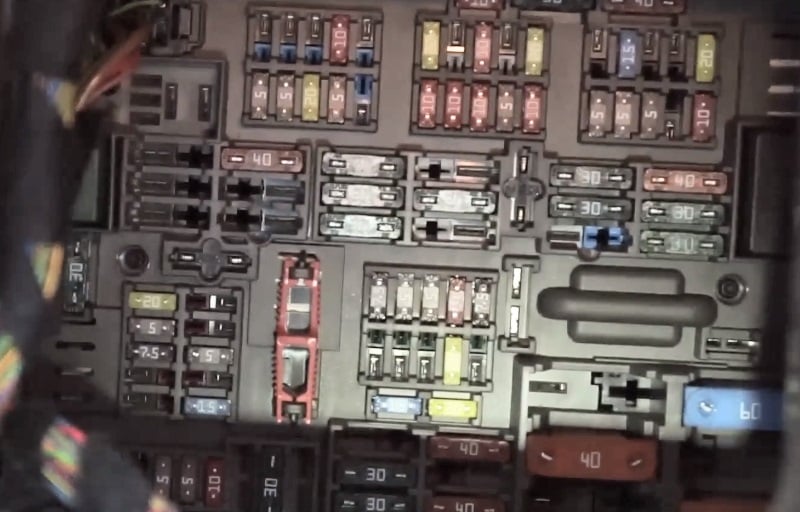
 Title : Thread 2006 E60 530d M Sport Fuse Box Diagram Bmw 1 Series Wiring Diagram
Category : Wiring Diagram
Format : PDF
Title : Thread 2006 E60 530d M Sport Fuse Box Diagram Bmw 1 Series Wiring Diagram
Category : Wiring Diagram
Format : PDF