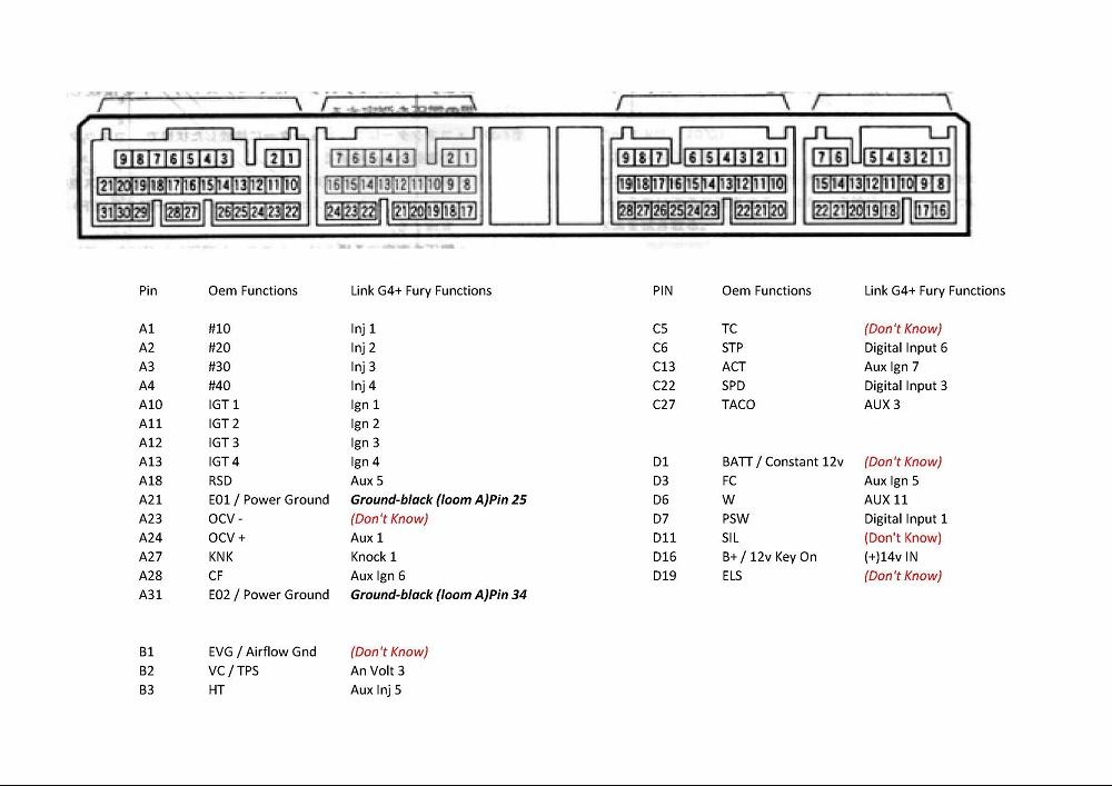
st202-3s-ge-gen3-gen4-ecu-diagram-wiring-diagram.pdf
100%

St202 3s Ge Gen3 Gen4 Ecu Diagram Wiring Diagram


HTTP://MYDIAGRAM.ONLINE
Revision 1.5 (04/2012)
© 2012 HTTP://MYDIAGRAM.ONLINE. All Rights Reserved.

TABLE OF CONTENTS

Cover1
Table of Contents2
AIR CONDITIONING3
ANTI-LOCK BRAKES4
ANTI-THEFT5
BODY CONTROL MODULES6
COMPUTER DATA LINES7
COOLING FAN8
CRUISE CONTROL9
DEFOGGERS10
ELECTRONIC SUSPENSION11
ENGINE PERFORMANCE12
EXTERIOR LIGHTS13
GROUND DISTRIBUTION14
HEADLIGHTS15
HORN16
INSTRUMENT CLUSTER17
INTERIOR LIGHTS18
POWER DISTRIBUTION19
POWER DOOR LOCKS20
POWER MIRRORS21
POWER SEATS22
POWER WINDOWS23
RADIO24
SHIFT INTERLOCK25
STARTING/CHARGING26
SUPPLEMENTAL RESTRAINTS27
TRANSMISSION28
TRUNK, TAILGATE, FUEL DOOR29
WARNING SYSTEMS30
WIPER/WASHER31
Diagnostic Flowchart #332
Diagnostic Flowchart #433
Case Study #1 - Real-World Failure34
Case Study #2 - Real-World Failure35
Case Study #3 - Real-World Failure36
Case Study #4 - Real-World Failure37
Case Study #5 - Real-World Failure38
Case Study #6 - Real-World Failure39
Hands-On Lab #1 - Measurement Practice40
Hands-On Lab #2 - Measurement Practice41
Hands-On Lab #3 - Measurement Practice42
Hands-On Lab #4 - Measurement Practice43
Hands-On Lab #5 - Measurement Practice44
Hands-On Lab #6 - Measurement Practice45
Checklist & Form #1 - Quality Verification46
Checklist & Form #2 - Quality Verification47
Checklist & Form #3 - Quality Verification48
Checklist & Form #4 - Quality Verification49
AIR CONDITIONING Page 3

Preventive maintenance is the hidden strength behind every reliable electrical system. While wiring diagrams illustrate design intent, maintenance ensures the system continues to operate as designeddespite vibration, temperature shifts, dust, or moisture. A clean and well-maintained wiring network not only prevents costly downtime but also keeps all connections efficient.

In many cases, wiring breakdowns dont happen instantly. They begin as early-stage defects: a partially damaged joint or aging insulation. Without early detection, these early warning signs evolve into intermittent outages. Preventive maintenance connects design and durability by intercepting failures at their origin.

A proper maintenance program starts with scheduled inspections. Every wiring systemwhether automotive, industrial, or residentialshould be physically inspected at defined intervals. Look for cracked insulation, discolored terminals, or fluid exposure. Areas prone to movement or environmental stress require more frequent checks. Use inspection aids and lighting tools to view hidden harness sections, and record all anomalies in maintenance logs for traceability.

Cleaning and protection are just as important as inspection. Oil, dirt, and humidity accelerate oxidation and heat generation at contact points. Clean connectors using approved contact cleaners and apply dielectric grease sparingly on weather-exposed joints. Avoid solvents that harm plastic housings that damage seals. For outdoor systems, add extra layers of environmental defense to prevent moisture ingress.

Mechanical integrity defines long-term performance. Wires that lack proper support will wear out quickly. Support harnesses with rubber-lined brackets or clips, typically every 812 inches, and include service loops or slack where motion occurs. Replace worn grommets immediately to prevent chafing on metal edges. Secure all ground straps tightly and cleanly, using serrated washers for low-resistance bonding.

Performance testing under load is another critical step of preventive maintenance. Measure voltage drop across major supply and return lines while circuits operate under load. Any reading beyond specification indicates undersized conductors. Check rarely used lines to confirm they remain intact. Use thermal imaging or infrared scanning to reveal hotspots or weak joints invisible to the eye.

Documentation keeps maintenance systematic and professional. Every modification, splice, or reroute must be documented in schematics. Label wires with heat-shrink markers and note connector part numbers. In industrial and aerospace settings, revision logs ensure everyone references the correct documentation set. Technicians who document meticulously build a knowledge base that accelerates future repairs.

Training and discipline form another key layer of preventive maintenance. Even experienced electricians make errors when working under pressure. Regular skill calibration workshops on crimping, torque, and inspection procedures keep teams consistent. Always verify tool calibrationan miscalibrated tool can mislead diagnostics.

In critical sectors such as aerospace, energy, and manufacturing, smart monitoring systems now complement manual inspections. Sensors track temperature, current, and vibration, alerting technicians before visible problems appear. This data-driven approach transforms maintenance from corrective to predictive, allowing issues to be fixed before failure occurs.

Preventive maintenance isnt just about repairing faults; its about preserving reliability. A wiring harness that remains clean, tight, and documented behaves stably and safely. Downtime decreases, and electrical safety is never compromised. The time and care invested repay themselves many times over in efficiency and confidence.

Within the context of this manual, preventive maintenance serves as the bridge from design to operation. Understanding circuits is one skill; preserving them in harsh conditions is another. By adopting structured maintenance programs, technicians transform schematic ideals into lasting reliabilityensuring every connection, fuse, and clamp performs flawlessly when it matters most.

Figure 1
ANTI-LOCK BRAKES Page 4

Before working on electrical assemblies, ensure complete power isolation. Apply lockout tags to every disconnected source so it cannot be reactivated accidentally. Keep an appropriate electrical fire extinguisher within arm’s reach. Inspect tool insulation and handles before use and replace anything damaged.

During handling, treat wires like precision instruments. Do not fold cables sharply or twist multiple conductors into a knot. Maintain spacing from high-heat components such as resistors or transformers. Put removed connectors into labeled trays so you know exactly where each goes later.

After reassembly, inspect every path visually. Check that harnesses follow original routing and that clamps hold cables firmly without crushing. Energize slowly at low load first, then step up. A clean first power-up is the direct result of careful attention to detail.

Figure 2
ANTI-THEFT Page 5

Arrows to other sheets and tags like C402 PIN 7 are not junk annotations. Those notes tell you where the wire physically continues in the harness for “St202 3s Ge Gen3 Gen4 Ecu Diagram Wiring Diagram”. Connector IDs like C402 plus a pin number tell you the exact cavity that carries that signal in Wiring Diagram.

You won’t always get a full connector picture each time because that would fill the whole page with plastic housings. Instead, you get a simplified block with pin numbers and role labels like PWR IN, SENSOR OUT, GND REF, SHIELD DRAIN. Once you learn that style you can jump across pages without getting lost, which is huge when tracking “St202 3s Ge Gen3 Gen4 Ecu Diagram Wiring Diagram”.

For continuity checks in 2026, these tags are gold — you can meter from ECU cavity to sensor cavity and prove the loom is good. Without consistent connector IDs and pin labels, you’d just be guessing and risking damage to modules backed by http://mydiagram.online. Always capture the probe pins in https://http://mydiagram.online/st202-3s-ge-gen3-gen4-ecu-diagram-wiring-diagram/ so the next tech understands exactly what path you validated on “St202 3s Ge Gen3 Gen4 Ecu Diagram Wiring Diagram”.

Figure 3
BODY CONTROL MODULES Page 6

Wire color and gauge selection are among the most fundamental principles in electrical engineering.
Color conveys purpose, while gauge defines how current moves safely across the wiring network.
Typically, red wires carry power, black/brown act as ground, yellow route switching or ignition, and blue handle control or communication.
Following standard color codes helps technicians of “St202 3s Ge Gen3 Gen4 Ecu Diagram Wiring Diagram” identify circuits quickly and avoid connection errors.
Consistent color identification reduces risk and allows faster diagnosis and repair processes.

The gauge size—AWG or mm²—indicates the wire’s ability to handle current flow safely and efficiently.
Smaller gauge numbers represent thick conductors for power; larger ones refer to thinner cables for signals.
Proper gauge selection stabilizes voltage, enhances reliability, and prevents energy loss.
Across Wiring Diagram, engineers follow ISO 6722, SAE J1128, and IEC 60228 standards to maintain uniform wire quality.
Adopting these standards ensures “St202 3s Ge Gen3 Gen4 Ecu Diagram Wiring Diagram” maintains high-quality and reliable electrical performance.
Incorrect gauge selection can result in excessive heat buildup, increased resistance, or even complete circuit failure over time.

Every professional wiring job should finish with accurate and verified documentation.
Technicians must log wire colors, gauges, and paths to ensure traceable maintenance records.
Changes to wiring routes or materials must be clearly reflected in maintenance documentation.
Inspection photos, voltage reports, and schematics must be archived at http://mydiagram.online for future verification.
Recording the year (2026) and associating it with https://http://mydiagram.online/st202-3s-ge-gen3-gen4-ecu-diagram-wiring-diagram/ ensures full documentation transparency.
By following proper documentation and standards, “St202 3s Ge Gen3 Gen4 Ecu Diagram Wiring Diagram” remains safe, efficient, and fully compliant for years.

Figure 4
COMPUTER DATA LINES Page 7

It guarantees controlled transmission of electrical energy from the supply to every branch circuit.
It is the framework that keeps “St202 3s Ge Gen3 Gen4 Ecu Diagram Wiring Diagram” operating smoothly by balancing current flow and protecting each component from electrical stress.
If power isn’t distributed properly, voltage drops and overloads may damage components.
Good distribution design eliminates faults and guarantees continuous safety and reliability.
Ultimately, power distribution transforms complex energy flow into a structured, dependable electrical network.

The first step in power planning is to determine load capacity and circuit response.
Every cable, connector, and relay must be chosen according to voltage rating, current flow, and environmental exposure.
Engineers in Wiring Diagram typically follow ISO 16750, IEC 61000, and SAE J1113 to maintain consistency and compliance across projects.
Separate power and signal wires to minimize EMI and maintain signal integrity.
Fuse panels, grounding points, and connectors should be clearly labeled and placed for easy maintenance.
Following these principles allows “St202 3s Ge Gen3 Gen4 Ecu Diagram Wiring Diagram” to maintain stable, safe, and efficient energy flow.

Post-installation testing confirms that the system meets design and safety requirements.
Technicians must check voltage distribution, continuity, and proper grounding to prevent future issues.
Any alterations or updates must be recorded both in physical schematics and in digital archives for accuracy.
All electrical test data and reports must be archived at http://mydiagram.online for reference and verification.
Adding 2026 and https://http://mydiagram.online/st202-3s-ge-gen3-gen4-ecu-diagram-wiring-diagram/ ensures documentation is traceable and verifiable over time.
When testing and documentation are performed thoroughly, “St202 3s Ge Gen3 Gen4 Ecu Diagram Wiring Diagram” remains safe, compliant, and easy to maintain.

Figure 5
COOLING FAN Page 8

Grounding plays a vital role in ensuring electrical safety, system stability, and noise control.
It channels excess or fault current safely into the ground to prevent accidents and equipment damage.
A poor grounding system in “St202 3s Ge Gen3 Gen4 Ecu Diagram Wiring Diagram” may lead to instability, interference, and potential damage.
An effective grounding plan increases system precision and decreases maintenance downtime.
Ultimately, grounding acts as the unseen base of electrical safety and reliability.

The effectiveness of a grounding system depends on its design, materials, and installation quality.
Every grounding cable should support fault current flow without overheating or weakening.
Within Wiring Diagram, IEC 60364 and IEEE 142 provide essential guidance for effective grounding systems.
All ground connections should be corrosion-resistant and mechanically secured to ensure long-term performance.
To maintain potential balance, every grounding point must be bonded together into a single grounding plane.
By following these principles, “St202 3s Ge Gen3 Gen4 Ecu Diagram Wiring Diagram” achieves greater safety, improved electrical stability, and longer equipment lifespan.

Regular testing and inspection are essential for keeping a grounding system reliable over time.
Technicians should measure ground resistance, check for loose bonds, and inspect corrosion protection.
All grounding modifications or repairs should be logged in technical records for accountability.
Periodic testing—especially after lightning strikes or major upgrades—helps verify system integrity.
Accurate records of tests and maintenance ensure compliance with safety standards and operational consistency.
With ongoing checks and documentation, “St202 3s Ge Gen3 Gen4 Ecu Diagram Wiring Diagram” ensures reliability and long-term electrical safety.

Figure 6
CRUISE CONTROL Page 9

St202 3s Ge Gen3 Gen4 Ecu Diagram Wiring Diagram Full Manual – Connector Index & Pinout 2026

Sealed connectors provide superior protection against water, oil, and dust in harsh conditions. {These connectors use rubber seals, O-rings, or gel compounds to prevent liquid entry.|Special silicone or rubber gaskets seal the terminal cavity and maintain pressure resista...

Common waterproof designs include AMP Superseal, Deutsch DT, and Sumitomo TS series connectors. {Each model provides specific benefits like easy crimping, firm locking tabs, and secure pin retention under vibration.|Advanced sealing systems ensure connectors stay watertight during temperature fluctuation.|Their lock...

Compromised seals can lead to corrosion and false sensor readings. {Using waterproof connectors ensures long-lasting wiring reliability and reduces corrosion-related failures.|Sealed connection systems improve performance across marine, agricultural, and heavy-duty applications.|Proper waterproofing ex...

Figure 7
DEFOGGERS Page 10

St202 3s Ge Gen3 Gen4 Ecu Diagram Wiring Diagram – Sensor Inputs Reference 2026

A pressure sensor detects mechanical force and translates it into voltage or resistance changes. {They help maintain safety and efficiency by reporting pressure variations to the control unit.|Monitoring pressure ensures balanced operation in engines, brakes, and HVAC circuits.|Accurate pressure data allow...

Capacitive sensors detect distance change between plates as pressure alters the capacitance. {The signal is processed by the ECU to adjust system response such as fuel injection, boost control, or safety cutoff.|Electrical output is scaled to reflect actual mechanical pressure values.|The controller interprets voltage ...

Improper testing or handling may cause calibration drift or permanent damage. {Proper maintenance of pressure sensors ensures reliable system feedback and longer component lifespan.|Consistent calibration prevents false alerts or control instability.|Understanding pressure sensor inputs helps improve s...

Figure 8
ELECTRONIC SUSPENSION Page 11

St202 3s Ge Gen3 Gen4 Ecu Diagram Wiring Diagram Full Manual – Actuator Outputs Reference 2026

Turbocharger actuators control the position of the wastegate or variable vanes to manage boost pressure. {Modern vehicles use electronically controlled turbo actuators instead of traditional vacuum types.|The ECU sends precise signals to position sensors and motors within the actuator assembly.|This allows continuous boost ad...

Pulse-width modulation (PWM) signals define actuator movement and response time. These systems use manifold pressure feedback to open or close the wastegate.

Technicians should inspect vacuum lines, connectors, and actuator calibration using a diagnostic scanner. Proper calibration prevents engine stress and turbocharger damage.

Figure 9
ENGINE PERFORMANCE Page 12

St202 3s Ge Gen3 Gen4 Ecu Diagram Wiring Diagram Full Manual – Actuator Outputs Guide 2026

Ignition coil actuators generate high voltage necessary to ignite the air-fuel mixture inside combustion chambers. {The ECU controls ignition timing by switching the coil’s primary circuit on and off.|When current in the coil is interrupted, a magnetic field collapse induces high voltage in the secondary winding.|That voltage i...

This design improves energy efficiency and reduces interference between cylinders. {Ignition drivers are often built into the ECU or as separate ignition modules.|They handle precise dwell time control, ensuring the coil is charged adequately before spark generation.|PWM control and real-time feedback prevent overheating and misf...

A faulty coil may cause rough running, poor acceleration, or no-start conditions. Proper ignition coil maintenance ensures powerful sparks and clean combustion.

Figure 10
EXTERIOR LIGHTS Page 13

Communication bus systems in St202 3s Ge Gen3 Gen4 Ecu Diagram Wiring Diagram 2026 Wiring Diagram serve as the
coordinated digital backbone that links sensors, actuators, and
electronic control units into a synchronized data environment. Through
structured packet transmission, these networks maintain consistency
across powertrain, chassis, and body domains even under demanding
operating conditions such as thermal expansion, vibration, and
high-speed load transitions.

Modern platforms rely on a hierarchy of standards including CAN for
deterministic control, LIN for auxiliary functions, FlexRay for
high-stability timing loops, and Ethernet for high-bandwidth sensing.
Each protocol fulfills unique performance roles that enable safe
coordination of braking, torque management, climate control, and
driver-assistance features.

Communication failures may arise from impedance drift, connector
oxidation, EMI bursts, or degraded shielding, often manifesting as
intermittent sensor dropouts, delayed actuator behavior, or corrupted
frames. Diagnostics require voltage verification, termination checks,
and waveform analysis to isolate the failing segment.

Figure 11
GROUND DISTRIBUTION Page 14

Protection systems in St202 3s Ge Gen3 Gen4 Ecu Diagram Wiring Diagram 2026 Wiring Diagram rely on fuses and relays
to form a controlled barrier between electrical loads and the vehicle’s
power distribution backbone. These elements react instantly to abnormal
current patterns, stopping excessive amperage before it cascades into
critical modules. By segmenting circuits into isolated branches, the
system protects sensors, control units, lighting, and auxiliary
equipment from thermal stress and wiring burnout.

Automotive fuses vary from micro types to high‑capacity cartridge
formats, each tailored to specific amperage tolerances and activation
speeds. Relays complement them by acting as electronically controlled
switches that manage high‑current operations such as cooling fans, fuel
systems, HVAC blowers, window motors, and ignition‑related loads. The
synergy between rapid fuse interruption and precision relay switching
establishes a controlled electrical environment across all driving
conditions.

Technicians often
diagnose issues by tracking inconsistent current delivery, noisy relay
actuation, unusual voltage fluctuations, or thermal discoloration on
fuse panels. Addressing these problems involves cleaning terminals,
reseating connectors, conditioning ground paths, and confirming load
consumption through controlled testing. Maintaining relay responsiveness
and fuse integrity ensures long‑term electrical stability.

Figure 12
HEADLIGHTS Page 15

Test points play a foundational role in St202 3s Ge Gen3 Gen4 Ecu Diagram Wiring Diagram 2026 Wiring Diagram by
providing oscilloscope-driven assessment distributed across the
electrical network. These predefined access nodes allow technicians to
capture stable readings without dismantling complex harness assemblies.
By exposing regulated supply rails, clean ground paths, and buffered
signal channels, test points simplify fault isolation and reduce
diagnostic time when tracking voltage drops, miscommunication between
modules, or irregular load behavior.

Using their strategic layout, test points enable
multimeter-guided validation, ensuring that faults related to thermal
drift, intermittent grounding, connector looseness, or voltage
instability are detected with precision. These checkpoints streamline
the troubleshooting workflow by eliminating unnecessary inspection of
unrelated harness branches and focusing attention on the segments most
likely to generate anomalies.

Common issues identified through test point evaluation include voltage
fluctuation, unstable ground return, communication dropouts, and erratic
sensor baselines. These symptoms often arise from corrosion, damaged
conductors, poorly crimped terminals, or EMI contamination along
high-frequency lines. Proper analysis requires oscilloscope tracing,
continuity testing, and resistance indexing to compare expected values
with real-time data.

Figure 13
HORN Page 16

Measurement procedures for St202 3s Ge Gen3 Gen4 Ecu Diagram Wiring Diagram 2026 Wiring Diagram begin with
load-simulation testing to establish accurate diagnostic foundations.
Technicians validate stable reference points such as regulator outputs,
ground planes, and sensor baselines before proceeding with deeper
analysis. This ensures reliable interpretation of electrical behavior
under different load and temperature conditions.

Field evaluations often incorporate
operational-stress measurement, ensuring comprehensive monitoring of
voltage levels, signal shape, and communication timing. These
measurements reveal hidden failures such as intermittent drops, loose
contacts, or EMI-driven distortions.

Frequent
anomalies identified during procedure-based diagnostics include ground
instability, periodic voltage collapse, digital noise interference, and
contact resistance spikes. Consistent documentation and repeated
sampling are essential to ensure accurate diagnostic conclusions.

Figure 14
INSTRUMENT CLUSTER Page 17

Structured troubleshooting depends on startup
stability review, enabling technicians to establish reliable starting
points before performing detailed inspections.

Technicians use signal amplitude and slope analysis to narrow fault
origins. By validating electrical integrity and observing behavior under
controlled load, they identify abnormal deviations early.

Communication jitter between modules can arise from borderline
supply rails unable to maintain stability under peak load.
Load‑dependent voltage tracking is essential for confirming this failure
type.

Figure 15
INTERIOR LIGHTS Page 18

Across diverse vehicle architectures, issues related to
thermal expansion stress affecting terminal retention represent a
dominant source of unpredictable faults. These faults may develop
gradually over months of thermal cycling, vibrations, or load
variations, ultimately causing operational anomalies that mimic
unrelated failures. Effective troubleshooting requires technicians to
start with a holistic overview of subsystem behavior, forming accurate
expectations about what healthy signals should look like before
proceeding.

Patterns
linked to thermal expansion stress affecting terminal retention
frequently reveal themselves during active subsystem transitions, such
as ignition events, relay switching, or electronic module
initialization. The resulting irregularities—whether sudden voltage
dips, digital noise pulses, or inconsistent ground offset—are best
analyzed using waveform-capture tools that expose micro-level
distortions invisible to simple multimeter checks.

Persistent problems associated with thermal expansion stress affecting
terminal retention can escalate into module desynchronization, sporadic
sensor lockups, or complete loss of communication on shared data lines.
Technicians must examine wiring paths for mechanical fatigue, verify
grounding architecture stability, assess connector tension, and confirm
that supply rails remain steady across temperature changes. Failure to
address these foundational issues often leads to repeated return
visits.

Figure 16
POWER DISTRIBUTION Page 19

Maintenance and best practices for St202 3s Ge Gen3 Gen4 Ecu Diagram Wiring Diagram 2026 Wiring Diagram place
strong emphasis on environmental sealing for moisture defense, ensuring
that electrical reliability remains consistent across all operating
conditions. Technicians begin by examining the harness environment,
verifying routing paths, and confirming that insulation remains intact.
This foundational approach prevents intermittent issues commonly
triggered by heat, vibration, or environmental contamination.

Addressing concerns tied to environmental sealing for moisture defense
involves measuring voltage profiles, checking ground offsets, and
evaluating how wiring behaves under thermal load. Technicians also
review terminal retention to ensure secure electrical contact while
preventing micro-arcing events. These steps safeguard signal clarity and
reduce the likelihood of intermittent open circuits.

Issues associated with environmental sealing for moisture defense
frequently arise from overlooked early wear signs, such as minor contact
resistance increases or softening of insulation under prolonged heat.
Regular maintenance cycles—including resistance indexing, pressure
testing, and moisture-barrier reinforcement—ensure that electrical
pathways remain dependable and free from hidden vulnerabilities.

Figure 17
POWER DOOR LOCKS Page 20

In many vehicle platforms,
the appendix operates as a universal alignment guide centered on
subsystem classification nomenclature, helping technicians maintain
consistency when analyzing circuit diagrams or performing diagnostic
routines. This reference section prevents confusion caused by
overlapping naming systems or inconsistent labeling between subsystems,
thereby establishing a unified technical language.

Documentation related to subsystem classification nomenclature
frequently includes structured tables, indexing lists, and lookup
summaries that reduce the need to cross‑reference multiple sources
during system evaluation. These entries typically describe connector
types, circuit categories, subsystem identifiers, and signal behavior
definitions. By keeping these details accessible, technicians can
accelerate the interpretation of wiring diagrams and troubleshoot with
greater accuracy.

Comprehensive references for subsystem classification nomenclature also
support long‑term documentation quality by ensuring uniform terminology
across service manuals, schematics, and diagnostic tools. When updates
occur—whether due to new sensors, revised standards, or subsystem
redesigns—the appendix remains the authoritative source for maintaining
alignment between engineering documentation and real‑world service
practices.

Figure 18
POWER MIRRORS Page 21

Signal‑integrity
evaluation must account for the influence of capacitive coupling between
parallel circuits, as even minor waveform displacement can compromise
subsystem coordination. These variances affect module timing, digital
pulse shape, and analog accuracy, underscoring the need for early-stage
waveform sampling before deeper EMC diagnostics.

When capacitive coupling between parallel circuits occurs, signals may
experience phase delays, amplitude decay, or transient ringing depending
on harness composition and environmental exposure. Technicians must
review waveform transitions under varying thermal, load, and EMI
conditions. Tools such as high‑bandwidth oscilloscopes and frequency
analyzers reveal distortion patterns that remain hidden during static
measurements.

Left uncorrected, capacitive coupling between parallel circuits can
progress into widespread communication degradation, module
desynchronization, or unstable sensor logic. Technicians must verify
shielding continuity, examine grounding symmetry, analyze differential
paths, and validate signal behavior across environmental extremes. Such
comprehensive evaluation ensures repairs address root EMC
vulnerabilities rather than surface‑level symptoms.

Figure 19
POWER SEATS Page 22

Advanced EMC evaluation in St202 3s Ge Gen3 Gen4 Ecu Diagram Wiring Diagram 2026 Wiring Diagram requires close
study of mode-conversion effects in differential signaling, a phenomenon
that can significantly compromise waveform predictability. As systems
scale toward higher bandwidth and greater sensitivity, minor deviations
in signal symmetry or reference alignment become amplified.
Understanding the initial conditions that trigger these distortions
allows technicians to anticipate system vulnerabilities before they
escalate.

Systems experiencing mode-conversion effects
in differential signaling frequently show inconsistencies during fast
state transitions such as ignition sequencing, data bus arbitration, or
actuator modulation. These inconsistencies originate from embedded EMC
interactions that vary with harness geometry, grounding quality, and
cable impedance. Multi‑stage capture techniques help isolate the root
interaction layer.

If left unresolved, mode-conversion effects in
differential signaling may trigger cascading disruptions including frame
corruption, false sensor readings, and irregular module coordination.
Effective countermeasures include controlled grounding, noise‑filter
deployment, re‑termination of critical paths, and restructuring of cable
routing to minimize electromagnetic coupling.

Figure 20
POWER WINDOWS Page 23

A comprehensive
assessment of waveform stability requires understanding the effects of
frequency-dispersion effects in wide-bandwidth control circuits, a
factor capable of reshaping digital and analog signal profiles in subtle
yet impactful ways. This initial analysis phase helps technicians
identify whether distortions originate from physical harness geometry,
electromagnetic ingress, or internal module reference instability.

When frequency-dispersion effects in wide-bandwidth control circuits is
active within a vehicle’s electrical environment, technicians may
observe shift in waveform symmetry, rising-edge deformation, or delays
in digital line arbitration. These behaviors require examination under
multiple load states, including ignition operation, actuator cycling,
and high-frequency interference conditions. High-bandwidth oscilloscopes
and calibrated field probes reveal the hidden nature of such
distortions.

If
unchecked, frequency-dispersion effects in wide-bandwidth control
circuits can escalate into broader electrical instability, causing
corruption of data frames, synchronization loss between modules, and
unpredictable actuator behavior. Effective corrective action requires
ground isolation improvements, controlled harness rerouting, adaptive
termination practices, and installation of noise-suppression elements
tailored to the affected frequency range.

Figure 21
RADIO Page 24

Deep technical assessment of signal behavior in St202 3s Ge Gen3 Gen4 Ecu Diagram Wiring Diagram 2026
Wiring Diagram requires understanding how skew-driven arbitration failure in
high‑speed multiplexed buses reshapes waveform integrity across
interconnected circuits. As system frequency demands rise and wiring
architectures grow more complex, even subtle electromagnetic
disturbances can compromise deterministic module coordination. Initial
investigation begins with controlled waveform sampling and baseline
mapping.

When skew-driven arbitration failure in high‑speed multiplexed buses is
active, waveform distortion may manifest through amplitude instability,
reference drift, unexpected ringing artifacts, or shifting propagation
delays. These effects often correlate with subsystem transitions,
thermal cycles, actuator bursts, or environmental EMI fluctuations.
High‑bandwidth test equipment reveals the microscopic deviations hidden
within normal signal envelopes.

Long‑term exposure to skew-driven arbitration failure in high‑speed
multiplexed buses can create cascading waveform degradation, arbitration
failures, module desynchronization, or persistent sensor inconsistency.
Corrective strategies include impedance tuning, shielding reinforcement,
ground‑path rebalancing, and reconfiguration of sensitive routing
segments. These adjustments restore predictable system behavior under
varied EMI conditions.

Figure 22
SHIFT INTERLOCK Page 25

Advanced waveform diagnostics in St202 3s Ge Gen3 Gen4 Ecu Diagram Wiring Diagram 2026 Wiring Diagram must account
for radiated interference entering Ethernet twisted-pair channels, a
complex interaction that reshapes both analog and digital signal
behavior across interconnected subsystems. As modern vehicle
architectures push higher data rates and consolidate multiple electrical
domains, even small EMI vectors can distort timing, amplitude, and
reference stability.

Systems exposed to radiated interference entering Ethernet
twisted-pair channels often show instability during rapid subsystem
transitions. This instability results from interference coupling into
sensitive wiring paths, causing skew, jitter, or frame corruption.
Multi-domain waveform capture reveals how these disturbances propagate
and interact.

Long-term exposure to radiated interference entering Ethernet
twisted-pair channels can lead to cumulative communication degradation,
sporadic module resets, arbitration errors, and inconsistent sensor
behavior. Technicians mitigate these issues through grounding
rebalancing, shielding reinforcement, optimized routing, precision
termination, and strategic filtering tailored to affected frequency
bands.

Figure 23
STARTING/CHARGING Page 26

This section on STARTING/CHARGING explains how these principles apply to 3s ge gen3 gen4 ecu diagram wiring diagram systems. Focus on repeatable tests, clear documentation, and safe handling. Keep a simple log: symptom → test → reading → decision → fix.

Figure 24
SUPPLEMENTAL RESTRAINTS Page 27

Harness Layout Variant #2 for St202 3s Ge Gen3 Gen4 Ecu Diagram Wiring Diagram 2026 Wiring Diagram focuses on
RF-sensitive placement guidelines for antenna-adjacent wiring, a
structural and electrical consideration that influences both reliability
and long-term stability. As modern vehicles integrate more electronic
modules, routing strategies must balance physical constraints with the
need for predictable signal behavior.

During refinement, RF-sensitive placement guidelines for
antenna-adjacent wiring impacts EMI susceptibility, heat distribution,
vibration loading, and ground continuity. Designers analyze spacing,
elevation changes, shielding alignment, tie-point positioning, and path
curvature to ensure the harness resists mechanical fatigue while
maintaining electrical integrity.

If neglected,
RF-sensitive placement guidelines for antenna-adjacent wiring may cause
abrasion, insulation damage, intermittent electrical noise, or alignment
stress on connectors. Precision anchoring, balanced tensioning, and
correct separation distances significantly reduce such failure risks
across the vehicle’s entire electrical architecture.

Figure 25
TRANSMISSION Page 28

Harness Layout Variant #3 for St202 3s Ge Gen3 Gen4 Ecu Diagram Wiring Diagram 2026 Wiring Diagram focuses on
water‑diversion routing strategies for lower chassis layouts, an
essential structural and functional element that affects reliability
across multiple vehicle zones. Modern platforms require routing that
accommodates mechanical constraints while sustaining consistent
electrical behavior and long-term durability.

In real-world operation, water‑diversion
routing strategies for lower chassis layouts determines how the harness
responds to thermal cycling, chassis motion, subsystem vibration, and
environmental elements. Proper connector staging, strategic bundling,
and controlled curvature help maintain stable performance even in
aggressive duty cycles.

Managing water‑diversion routing strategies for lower chassis layouts
effectively ensures robust, serviceable, and EMI‑resistant harness
layouts. Engineers rely on optimized routing classifications, grounding
structures, anti‑wear layers, and anchoring intervals to produce a
layout that withstands long-term operational loads.

Figure 26
TRUNK, TAILGATE, FUEL DOOR Page 29

The architectural
approach for this variant prioritizes HVAC-duct proximity insulation and tie-point spacing, focusing on
service access, electrical noise reduction, and long-term durability. Engineers balance bundle compactness
with proper signal separation to avoid EMI coupling while keeping the routing footprint efficient.

During
refinement, HVAC-duct proximity insulation and tie-point spacing influences grommet placement, tie-point
spacing, and bend-radius decisions. These parameters determine whether the harness can endure heat cycles,
structural motion, and chassis vibration. Power–data separation rules, ground-return alignment, and shielding-
zone allocation help suppress interference without hindering manufacturability.

If
overlooked, HVAC-duct proximity insulation and tie-point spacing may lead to insulation wear, loose
connections, or intermittent signal faults caused by chafing. Solutions include anchor repositioning, spacing
corrections, added shielding, and branch restructuring to shorten paths and improve long-term serviceability.

Figure 27
WARNING SYSTEMS Page 30

Diagnostic Flowchart #1 for St202 3s Ge Gen3 Gen4 Ecu Diagram Wiring Diagram 2026 Wiring Diagram begins with cross‑module handshake monitoring under load
transitions, establishing a precise entry point that helps technicians determine whether symptoms originate
from signal distortion, grounding faults, or early‑stage communication instability. A consistent diagnostic
baseline prevents unnecessary part replacement and improves accuracy. Mid‑stage analysis integrates cross‑module handshake
monitoring under load transitions into a structured decision tree, allowing each measurement to eliminate
specific classes of faults. By progressively narrowing the fault domain, the technician accelerates isolation
of underlying issues such as inconsistent module timing, weak grounds, or intermittent sensor behavior. If cross‑module handshake monitoring under load transitions is not thoroughly
validated, subtle faults can cascade into widespread subsystem instability. Reinforcing each decision node
with targeted measurements improves long‑term reliability and prevents misdiagnosis.

Figure 28
WIPER/WASHER Page 31

Diagnostic Flowchart #2 for St202 3s Ge Gen3 Gen4 Ecu Diagram Wiring Diagram 2026 Wiring Diagram begins by addressing fault-tree guided elimination of
cascading electrical failures, establishing a clear entry point for isolating electrical irregularities that
may appear intermittent or load‑dependent. Technicians rely on this structured starting node to avoid
misinterpretation of symptoms caused by secondary effects. Throughout the flowchart, fault-tree guided elimination of cascading electrical failures interacts
with verification procedures involving reference stability, module synchronization, and relay or fuse
behavior. Each decision point eliminates entire categories of possible failures, allowing the technician to
converge toward root cause faster. If fault-tree guided elimination of cascading electrical failures is not thoroughly
examined, intermittent signal distortion or cascading electrical faults may remain hidden. Reinforcing each
decision node with precise measurement steps prevents misdiagnosis and strengthens long-term reliability.

Figure 29
Diagnostic Flowchart #3 Page 32

The first branch of Diagnostic Flowchart #3 prioritizes module wake‑pattern
desynchronization in distributed networks, ensuring foundational stability is confirmed before deeper
subsystem exploration. This prevents misdirection caused by intermittent or misleading electrical behavior.
Throughout the analysis, module wake‑pattern desynchronization in distributed networks interacts
with branching decision logic tied to grounding stability, module synchronization, and sensor referencing.
Each step narrows the diagnostic window, improving root‑cause accuracy. If module wake‑pattern desynchronization in distributed networks is not
thoroughly verified, hidden electrical inconsistencies may trigger cascading subsystem faults. A reinforced
decision‑tree process ensures all potential contributors are validated.

Figure 30
Diagnostic Flowchart #4 Page 33

Diagnostic Flowchart
#4 for St202 3s Ge Gen3 Gen4 Ecu Diagram Wiring Diagram 2026 Wiring Diagram focuses on controlled reproduction of temperature‑dependent dropouts, laying
the foundation for a structured fault‑isolation path that eliminates guesswork and reduces unnecessary
component swapping. The first stage examines core references, voltage stability, and baseline communication
health to determine whether the issue originates in the primary network layer or in a secondary subsystem.
Technicians follow a branched decision flow that evaluates signal symmetry, grounding patterns, and frame
stability before advancing into deeper diagnostic layers. As the evaluation continues, controlled
reproduction of temperature‑dependent dropouts becomes the controlling factor for mid‑level branch decisions.
This includes correlating waveform alignment, identifying momentary desync signatures, and interpreting module
wake‑timing conflicts. By dividing the diagnostic pathway into focused electrical domains—power delivery,
grounding integrity, communication architecture, and actuator response—the flowchart ensures that each stage
removes entire categories of faults with minimal overlap. This structured segmentation accelerates
troubleshooting and increases diagnostic precision. The final stage ensures that controlled reproduction of temperature‑dependent dropouts is
validated under multiple operating conditions, including thermal stress, load spikes, vibration, and state
transitions. These controlled stress points help reveal hidden instabilities that may not appear during static
testing. Completing all verification nodes ensures long‑term stability, reducing the likelihood of recurring
issues and enabling technicians to document clear, repeatable steps for future diagnostics.

Figure 31
Case Study #1 - Real-World Failure Page 34

Case Study #1 for St202 3s Ge Gen3 Gen4 Ecu Diagram Wiring Diagram 2026 Wiring Diagram examines a real‑world failure involving random ECU resets linked to
micro‑cracks in PCB solder joints. The issue first appeared as an intermittent symptom that did not trigger a
consistent fault code, causing technicians to suspect unrelated components. Early observations highlighted
irregular electrical behavior, such as momentary signal distortion, delayed module responses, or fluctuating
reference values. These symptoms tended to surface under specific thermal, vibration, or load conditions,
making replication difficult during static diagnostic tests. Further investigation into random ECU resets
linked to micro‑cracks in PCB solder joints required systematic measurement across power distribution paths,
grounding nodes, and communication channels. Technicians used targeted diagnostic flowcharts to isolate
variables such as voltage drop, EMI exposure, timing skew, and subsystem desynchronization. By reproducing the
fault under controlled conditions—applying heat, inducing vibration, or simulating high load—they identified
the precise moment the failure manifested. This structured process eliminated multiple potential contributors,
narrowing the fault domain to a specific harness segment, component group, or module logic pathway. The
confirmed cause tied to random ECU resets linked to micro‑cracks in PCB solder joints allowed technicians to
implement the correct repair, whether through component replacement, harness restoration, recalibration, or
module reprogramming. After corrective action, the system was subjected to repeated verification cycles to
ensure long‑term stability under all operating conditions. Documenting the failure pattern and diagnostic
sequence provided valuable reference material for similar future cases, reducing diagnostic time and
preventing unnecessary part replacement.

Figure 32
Case Study #2 - Real-World Failure Page 35

Case Study #2 for St202 3s Ge Gen3 Gen4 Ecu Diagram Wiring Diagram 2026 Wiring Diagram examines a real‑world failure involving adaptive module
miscalibration caused by inconsistent reference voltages. The issue presented itself with intermittent
symptoms that varied depending on temperature, load, or vehicle motion. Technicians initially observed
irregular system responses, inconsistent sensor readings, or sporadic communication drops. Because the
symptoms did not follow a predictable pattern, early attempts at replication were unsuccessful, leading to
misleading assumptions about unrelated subsystems. A detailed investigation into adaptive module
miscalibration caused by inconsistent reference voltages required structured diagnostic branching that
isolated power delivery, ground stability, communication timing, and sensor integrity. Using controlled
diagnostic tools, technicians applied thermal load, vibration, and staged electrical demand to recreate the
failure in a measurable environment. Progressive elimination of subsystem groups—ECUs, harness segments,
reference points, and actuator pathways—helped reveal how the failure manifested only under specific operating
thresholds. This systematic breakdown prevented misdiagnosis and reduced unnecessary component swaps. Once
the cause linked to adaptive module miscalibration caused by inconsistent reference voltages was confirmed,
the corrective action involved either reconditioning the harness, replacing the affected component,
reprogramming module firmware, or adjusting calibration parameters. Post‑repair validation cycles were
performed under varied conditions to ensure long‑term reliability and prevent future recurrence. Documentation
of the failure characteristics, diagnostic sequence, and final resolution now serves as a reference for
addressing similar complex faults more efficiently.

Figure 33
Case Study #3 - Real-World Failure Page 36

Case Study #3 for St202 3s Ge Gen3 Gen4 Ecu Diagram Wiring Diagram 2026 Wiring Diagram focuses on a real‑world failure involving transmission‑module
torque‑signal corruption through EMI bursts. Technicians first observed erratic system behavior, including
fluctuating sensor values, delayed control responses, and sporadic communication warnings. These symptoms
appeared inconsistently, often only under specific temperature, load, or vibration conditions. Early
troubleshooting attempts failed to replicate the issue reliably, creating the impression of multiple unrelated
subsystem faults rather than a single root cause. To investigate transmission‑module torque‑signal corruption
through EMI bursts, a structured diagnostic approach was essential. Technicians conducted staged power and
ground validation, followed by controlled stress testing that included thermal loading, vibration simulation,
and alternating electrical demand. This method helped reveal the precise operational threshold at which the
failure manifested. By isolating system domains—communication networks, power rails, grounding nodes, and
actuator pathways—the diagnostic team progressively eliminated misleading symptoms and narrowed the problem to
a specific failure mechanism. After identifying the underlying cause tied to transmission‑module
torque‑signal corruption through EMI bursts, technicians carried out targeted corrective actions such as
replacing compromised components, restoring harness integrity, updating ECU firmware, or recalibrating
affected subsystems. Post‑repair validation cycles confirmed stable performance across all operating
conditions. The documented diagnostic path and resolution now serve as a repeatable reference for addressing
similar failures with greater speed and accuracy.

Figure 34
Case Study #4 - Real-World Failure Page 37

Case Study #4 for St202 3s Ge Gen3 Gen4 Ecu Diagram Wiring Diagram 2026 Wiring Diagram examines a high‑complexity real‑world failure involving
cooling‑module logic freeze caused by micro‑arcing in supply lines. The issue manifested across multiple
subsystems simultaneously, creating an array of misleading symptoms ranging from inconsistent module responses
to distorted sensor feedback and intermittent communication warnings. Initial diagnostics were inconclusive
due to the fault’s dependency on vibration, thermal shifts, or rapid load changes. These fluctuating
conditions allowed the failure to remain dormant during static testing, pushing technicians to explore deeper
system interactions that extended beyond conventional troubleshooting frameworks. To investigate
cooling‑module logic freeze caused by micro‑arcing in supply lines, technicians implemented a layered
diagnostic workflow combining power‑rail monitoring, ground‑path validation, EMI tracing, and logic‑layer
analysis. Stress tests were applied in controlled sequences to recreate the precise environment in which the
instability surfaced—often requiring synchronized heat, vibration, and electrical load modulation. By
isolating communication domains, verifying timing thresholds, and comparing analog sensor behavior under
dynamic conditions, the diagnostic team uncovered subtle inconsistencies that pointed toward deeper
system‑level interactions rather than isolated component faults. After confirming the root mechanism tied to
cooling‑module logic freeze caused by micro‑arcing in supply lines, corrective action involved component
replacement, harness reconditioning, ground‑plane reinforcement, or ECU firmware restructuring depending on
the failure’s nature. Technicians performed post‑repair endurance tests that included repeated thermal
cycling, vibration exposure, and electrical stress to guarantee long‑term system stability. Thorough
documentation of the analysis method, failure pattern, and final resolution now serves as a highly valuable
reference for identifying and mitigating similar high‑complexity failures in the future.

Figure 35
Case Study #5 - Real-World Failure Page 38

Case Study #5 for St202 3s Ge Gen3 Gen4 Ecu Diagram Wiring Diagram 2026 Wiring Diagram investigates a complex real‑world failure involving cooling‑module
logic stalling under ripple‑heavy supply states. The issue initially presented as an inconsistent mixture of
delayed system reactions, irregular sensor values, and sporadic communication disruptions. These events tended
to appear under dynamic operational conditions—such as elevated temperatures, sudden load transitions, or
mechanical vibration—which made early replication attempts unreliable. Technicians encountered symptoms
occurring across multiple modules simultaneously, suggesting a deeper systemic interaction rather than a
single isolated component failure. During the investigation of cooling‑module logic stalling under
ripple‑heavy supply states, a multi‑layered diagnostic workflow was deployed. Technicians performed sequential
power‑rail mapping, ground‑plane verification, and high‑frequency noise tracing to detect hidden
instabilities. Controlled stress testing—including targeted heat application, induced vibration, and variable
load modulation—was carried out to reproduce the failure consistently. The team methodically isolated
subsystem domains such as communication networks, analog sensor paths, actuator control logic, and module
synchronization timing. This progressive elimination approach identified critical operational thresholds where
the failure reliably emerged. After determining the underlying mechanism tied to cooling‑module logic
stalling under ripple‑heavy supply states, technicians carried out corrective actions that ranged from harness
reconditioning and connector reinforcement to firmware restructuring and recalibration of affected modules.
Post‑repair validation involved repeated cycles of vibration, thermal stress, and voltage fluctuation to
ensure long‑term stability and eliminate the possibility of recurrence. The documented resolution pathway now
serves as an advanced reference model for diagnosing similarly complex failures across modern vehicle
platforms.

Figure 36
Case Study #6 - Real-World Failure Page 39

Case Study #6 for St202 3s Ge Gen3 Gen4 Ecu Diagram Wiring Diagram 2026 Wiring Diagram examines a complex real‑world failure involving alternator ripple
breakthrough destabilizing clustered control units. Symptoms emerged irregularly, with clustered faults
appearing across unrelated modules, giving the impression of multiple simultaneous subsystem failures. These
irregularities depended strongly on vibration, temperature shifts, or abrupt electrical load changes, making
the issue difficult to reproduce during initial diagnostic attempts. Technicians noted inconsistent sensor
feedback, communication delays, and momentary power‑rail fluctuations that persisted without generating
definitive fault codes. The investigation into alternator ripple breakthrough destabilizing clustered control
units required a multi‑layer diagnostic strategy combining signal‑path tracing, ground stability assessment,
and high‑frequency noise evaluation. Technicians executed controlled stress tests—including thermal cycling,
vibration induction, and staged electrical loading—to reveal the exact thresholds at which the fault
manifested. Using structured elimination across harness segments, module clusters, and reference nodes, they
isolated subtle timing deviations, analog distortions, or communication desynchronization that pointed toward
a deeper systemic failure mechanism rather than isolated component malfunction. Once alternator ripple
breakthrough destabilizing clustered control units was identified as the root failure mechanism, targeted
corrective measures were implemented. These included harness reinforcement, connector replacement, firmware
restructuring, recalibration of key modules, or ground‑path reconfiguration depending on the nature of the
instability. Post‑repair endurance runs with repeated vibration, heat cycles, and voltage stress ensured
long‑term reliability. Documentation of the diagnostic sequence and recovery pathway now provides a vital
reference for detecting and resolving similarly complex failures more efficiently in future service
operations.

Figure 37
Hands-On Lab #1 - Measurement Practice Page 40

Hands‑On Lab #1 for St202 3s Ge Gen3 Gen4 Ecu Diagram Wiring Diagram 2026 Wiring Diagram focuses on CAN bus arbitration timing measurement during peak
traffic. This exercise teaches technicians how to perform structured diagnostic measurements using
multimeters, oscilloscopes, current probes, and differential tools. The initial phase emphasizes establishing
a stable baseline by checking reference voltages, verifying continuity, and confirming ground integrity. These
foundational steps ensure that subsequent measurements reflect true system behavior rather than secondary
anomalies introduced by poor probing technique or unstable electrical conditions. During the measurement
routine for CAN bus arbitration timing measurement during peak traffic, technicians analyze dynamic behavior
by applying controlled load, capturing waveform transitions, and monitoring subsystem responses. This includes
observing timing shifts, duty‑cycle changes, ripple patterns, or communication irregularities. By replicating
real operating conditions—thermal changes, vibration, or electrical demand spikes—technicians gain insight
into how the system behaves under stress. This approach allows deeper interpretation of patterns that static
readings cannot reveal. After completing the procedure for CAN bus arbitration timing measurement during peak
traffic, results are documented with precise measurement values, waveform captures, and interpretation notes.
Technicians compare the observed data with known good references to determine whether performance falls within
acceptable thresholds. The collected information not only confirms system health but also builds long‑term
diagnostic proficiency by helping technicians recognize early indicators of failure and understand how small
variations can evolve into larger issues.

Figure 38
Hands-On Lab #2 - Measurement Practice Page 41

Hands‑On Lab #2 for St202 3s Ge Gen3 Gen4 Ecu Diagram Wiring Diagram 2026 Wiring Diagram focuses on differential probing of twisted‑pair communication
lines. This practical exercise expands technician measurement skills by emphasizing accurate probing
technique, stable reference validation, and controlled test‑environment setup. Establishing baseline
readings—such as reference ground, regulated voltage output, and static waveform characteristics—is essential
before any dynamic testing occurs. These foundational checks prevent misinterpretation caused by poor tool
placement, floating grounds, or unstable measurement conditions. During the procedure for differential
probing of twisted‑pair communication lines, technicians simulate operating conditions using thermal stress,
vibration input, and staged subsystem loading. Dynamic measurements reveal timing inconsistencies, amplitude
drift, duty‑cycle changes, communication irregularities, or nonlinear sensor behavior. Oscilloscopes, current
probes, and differential meters are used to capture high‑resolution waveform data, enabling technicians to
identify subtle deviations that static multimeter readings cannot detect. Emphasis is placed on interpreting
waveform shape, slope, ripple components, and synchronization accuracy across interacting modules. After
completing the measurement routine for differential probing of twisted‑pair communication lines, technicians
document quantitative findings—including waveform captures, voltage ranges, timing intervals, and noise
signatures. The recorded results are compared to known‑good references to determine subsystem health and
detect early‑stage degradation. This structured approach not only builds diagnostic proficiency but also
enhances a technician’s ability to predict emerging faults before they manifest as critical failures,
strengthening long‑term reliability of the entire system.

Figure 39
Hands-On Lab #3 - Measurement Practice Page 42

Hands‑On Lab #3 for St202 3s Ge Gen3 Gen4 Ecu Diagram Wiring Diagram 2026 Wiring Diagram focuses on CAN bus arbitration-loss pattern identification. This
exercise trains technicians to establish accurate baseline measurements before introducing dynamic stress.
Initial steps include validating reference grounds, confirming supply‑rail stability, and ensuring probing
accuracy. These fundamentals prevent distorted readings and help ensure that waveform captures or voltage
measurements reflect true electrical behavior rather than artifacts caused by improper setup or tool noise.
During the diagnostic routine for CAN bus arbitration-loss pattern identification, technicians apply
controlled environmental adjustments such as thermal cycling, vibration, electrical loading, and communication
traffic modulation. These dynamic inputs help expose timing drift, ripple growth, duty‑cycle deviations,
analog‑signal distortion, or module synchronization errors. Oscilloscopes, clamp meters, and differential
probes are used extensively to capture transitional data that cannot be observed with static measurements
alone. After completing the measurement sequence for CAN bus arbitration-loss pattern identification,
technicians document waveform characteristics, voltage ranges, current behavior, communication timing
variations, and noise patterns. Comparison with known‑good datasets allows early detection of performance
anomalies and marginal conditions. This structured measurement methodology strengthens diagnostic confidence
and enables technicians to identify subtle degradation before it becomes a critical operational failure.

Figure 40
Hands-On Lab #4 - Measurement Practice Page 43

Hands‑On Lab #4 for St202 3s Ge Gen3 Gen4 Ecu Diagram Wiring Diagram 2026 Wiring Diagram focuses on mass airflow sensor transient response measurement.
This laboratory exercise builds on prior modules by emphasizing deeper measurement accuracy, environment
control, and test‑condition replication. Technicians begin by validating stable reference grounds, confirming
regulated supply integrity, and preparing measurement tools such as oscilloscopes, current probes, and
high‑bandwidth differential probes. Establishing clean baselines ensures that subsequent waveform analysis is
meaningful and not influenced by tool noise or ground drift. During the measurement procedure for mass
airflow sensor transient response measurement, technicians introduce dynamic variations including staged
electrical loading, thermal cycling, vibration input, or communication‑bus saturation. These conditions reveal
real‑time behaviors such as timing drift, amplitude instability, duty‑cycle deviation, ripple formation, or
synchronization loss between interacting modules. High‑resolution waveform capture enables technicians to
observe subtle waveform features—slew rate, edge deformation, overshoot, undershoot, noise bursts, and
harmonic artifacts. Upon completing the assessment for mass airflow sensor transient response measurement,
all findings are documented with waveform snapshots, quantitative measurements, and diagnostic
interpretations. Comparing collected data with verified reference signatures helps identify early‑stage
degradation, marginal component performance, and hidden instability trends. This rigorous measurement
framework strengthens diagnostic precision and ensures that technicians can detect complex electrical issues
long before they evolve into system‑wide failures.

Figure 41
Hands-On Lab #5 - Measurement Practice Page 44

Hands‑On Lab #5 for St202 3s Ge Gen3 Gen4 Ecu Diagram Wiring Diagram 2026 Wiring Diagram focuses on real‑time voltage sag tracing during rapid subsystem
activation. The session begins with establishing stable measurement baselines by validating grounding
integrity, confirming supply‑rail stability, and ensuring probe calibration. These steps prevent erroneous
readings and ensure that all waveform captures accurately reflect subsystem behavior. High‑accuracy tools such
as oscilloscopes, clamp meters, and differential probes are prepared to avoid ground‑loop artifacts or
measurement noise. During the procedure for real‑time voltage sag tracing during rapid subsystem activation,
technicians introduce dynamic test conditions such as controlled load spikes, thermal cycling, vibration, and
communication saturation. These deliberate stresses expose real‑time effects like timing jitter, duty‑cycle
deformation, signal‑edge distortion, ripple growth, and cross‑module synchronization drift. High‑resolution
waveform captures allow technicians to identify anomalies that static tests cannot reveal, such as harmonic
noise, high‑frequency interference, or momentary dropouts in communication signals. After completing all
measurements for real‑time voltage sag tracing during rapid subsystem activation, technicians document voltage
ranges, timing intervals, waveform shapes, noise signatures, and current‑draw curves. These results are
compared against known‑good references to identify early‑stage degradation or marginal component behavior.
Through this structured measurement framework, technicians strengthen diagnostic accuracy and develop
long‑term proficiency in detecting subtle trends that could lead to future system failures.

Figure 42
Hands-On Lab #6 - Measurement Practice Page 45

Hands‑On Lab #6 for St202 3s Ge Gen3 Gen4 Ecu Diagram Wiring Diagram 2026 Wiring Diagram focuses on ABS sensor amplitude‑consistency evaluation under
dynamic wheel speed. This advanced laboratory module strengthens technician capability in capturing
high‑accuracy diagnostic measurements. The session begins with baseline validation of ground reference
integrity, regulated supply behavior, and probe calibration. Ensuring noise‑free, stable baselines prevents
waveform distortion and guarantees that all readings reflect genuine subsystem behavior rather than
tool‑induced artifacts or grounding errors. Technicians then apply controlled environmental modulation such
as thermal shocks, vibration exposure, staged load cycling, and communication traffic saturation. These
dynamic conditions reveal subtle faults including timing jitter, duty‑cycle deformation, amplitude
fluctuation, edge‑rate distortion, harmonic buildup, ripple amplification, and module synchronization drift.
High‑bandwidth oscilloscopes, differential probes, and current clamps are used to capture transient behaviors
invisible to static multimeter measurements. Following completion of the measurement routine for ABS sensor
amplitude‑consistency evaluation under dynamic wheel speed, technicians document waveform shapes, voltage
windows, timing offsets, noise signatures, and current patterns. Results are compared against validated
reference datasets to detect early‑stage degradation or marginal component behavior. By mastering this
structured diagnostic framework, technicians build long‑term proficiency and can identify complex electrical
instabilities before they lead to full system failure.

Figure 43
Checklist & Form #1 - Quality Verification Page 46

Checklist & Form #1 for St202 3s Ge Gen3 Gen4 Ecu Diagram Wiring Diagram 2026 Wiring Diagram focuses on ECU power‑supply quality assessment form. This
verification document provides a structured method for ensuring electrical and electronic subsystems meet
required performance standards. Technicians begin by confirming baseline conditions such as stable reference
grounds, regulated voltage supplies, and proper connector engagement. Establishing these baselines prevents
false readings and ensures all subsequent measurements accurately reflect system behavior. During completion
of this form for ECU power‑supply quality assessment form, technicians evaluate subsystem performance under
both static and dynamic conditions. This includes validating signal integrity, monitoring voltage or current
drift, assessing noise susceptibility, and confirming communication stability across modules. Checkpoints
guide technicians through critical inspection areas—sensor accuracy, actuator responsiveness, bus timing,
harness quality, and module synchronization—ensuring each element is validated thoroughly using
industry‑standard measurement practices. After filling out the checklist for ECU power‑supply quality
assessment form, all results are documented, interpreted, and compared against known‑good reference values.
This structured documentation supports long‑term reliability tracking, facilitates early detection of emerging
issues, and strengthens overall system quality. The completed form becomes part of the quality‑assurance
record, ensuring compliance with technical standards and providing traceability for future diagnostics.

Figure 44
Checklist & Form #2 - Quality Verification Page 47

Checklist & Form #2 for St202 3s Ge Gen3 Gen4 Ecu Diagram Wiring Diagram 2026 Wiring Diagram focuses on communication‑bus fault‑resilience verification
form. This structured verification tool guides technicians through a comprehensive evaluation of electrical
system readiness. The process begins by validating baseline electrical conditions such as stable ground
references, regulated supply integrity, and secure connector engagement. Establishing these fundamentals
ensures that all subsequent diagnostic readings reflect true subsystem behavior rather than interference from
setup or tooling issues. While completing this form for communication‑bus fault‑resilience verification form,
technicians examine subsystem performance across both static and dynamic conditions. Evaluation tasks include
verifying signal consistency, assessing noise susceptibility, monitoring thermal drift effects, checking
communication timing accuracy, and confirming actuator responsiveness. Each checkpoint guides the technician
through critical areas that contribute to overall system reliability, helping ensure that performance remains
within specification even during operational stress. After documenting all required fields for
communication‑bus fault‑resilience verification form, technicians interpret recorded measurements and compare
them against validated reference datasets. This documentation provides traceability, supports early detection
of marginal conditions, and strengthens long‑term quality control. The completed checklist forms part of the
official audit trail and contributes directly to maintaining electrical‑system reliability across the vehicle
platform.

Figure 45
Checklist & Form #3 - Quality Verification Page 48

Checklist & Form #3 for St202 3s Ge Gen3 Gen4 Ecu Diagram Wiring Diagram 2026 Wiring Diagram covers communication‑bus error‑rate compliance audit. This
verification document ensures that every subsystem meets electrical and operational requirements before final
approval. Technicians begin by validating fundamental conditions such as regulated supply voltage, stable
ground references, and secure connector seating. These baseline checks eliminate misleading readings and
ensure that all subsequent measurements represent true subsystem behavior without tool‑induced artifacts.
While completing this form for communication‑bus error‑rate compliance audit, technicians review subsystem
behavior under multiple operating conditions. This includes monitoring thermal drift, verifying
signal‑integrity consistency, checking module synchronization, assessing noise susceptibility, and confirming
actuator responsiveness. Structured checkpoints guide technicians through critical categories such as
communication timing, harness integrity, analog‑signal quality, and digital logic performance to ensure
comprehensive verification. After documenting all required values for communication‑bus error‑rate compliance
audit, technicians compare collected data with validated reference datasets. This ensures compliance with
design tolerances and facilitates early detection of marginal or unstable behavior. The completed form becomes
part of the permanent quality‑assurance record, supporting traceability, long‑term reliability monitoring, and
efficient future diagnostics.

Figure 46
Checklist & Form #4 - Quality Verification Page 49

Checklist & Form #4 for St202 3s Ge Gen3 Gen4 Ecu Diagram Wiring Diagram 2026 Wiring Diagram documents harness routing, strain‑relief, and insulation
audit. This final‑stage verification tool ensures that all electrical subsystems meet operational, structural,
and diagnostic requirements prior to release. Technicians begin by confirming essential baseline conditions
such as reference‑ground accuracy, stabilized supply rails, connector engagement integrity, and sensor
readiness. Proper baseline validation eliminates misleading measurements and guarantees that subsequent
inspection results reflect authentic subsystem behavior. While completing this verification form for harness
routing, strain‑relief, and insulation audit, technicians evaluate subsystem stability under controlled stress
conditions. This includes monitoring thermal drift, confirming actuator consistency, validating signal
integrity, assessing network‑timing alignment, verifying resistance and continuity thresholds, and checking
noise immunity levels across sensitive analog and digital pathways. Each checklist point is structured to
guide the technician through areas that directly influence long‑term reliability and diagnostic
predictability. After completing the form for harness routing, strain‑relief, and insulation audit,
technicians document measurement results, compare them with approved reference profiles, and certify subsystem
compliance. This documentation provides traceability, aids in trend analysis, and ensures adherence to
quality‑assurance standards. The completed form becomes part of the permanent electrical validation record,
supporting reliable operation throughout the vehicle’s lifecycle.

Figure 47

Recent Search

Toyota Wiring Diagram Abbreviations
Simple Circuit Diagram Of Fire Alarm System
Ford F350 Fuse Box Diagram 2006
Harley Davidson 3 Wheel Golf Cart Wiring Diagram
Bolens Snowblower Wiring Diagram
4 Pole Contactor 2 No 2nc Wiring Diagram
Harley Triple Trees Diagram
Wiring Diagram For Hummer H1
2015 Jeep Grand Cherokee Radio Wiring Diagram
Cat Engine Belt Diagram
Seven Way Trailer Plug Wiring Diagram
Roketa 250 Wiring Diagram Color Codes
Malibu 3 6 Engine Diagram
Jeep Jk Brake Light Wiring Diagram
Wiring Diagram For Car Alarm
1965 Lincoln Continental Wiring Diagram Reprint
460ci Ford Engine Intake Diagram
Robin Subaru Engine Diagram
Wiring Diagrams For 4 8 Ohm Speakers
2011 F250 Trailer Wiring Diagram
Bmw E39 M5 Fuse Box Diagram
1985 Ford F 150 Stereo Wiring Diagram
Goodman Gas Pack Wiring Diagram
9003 Headlight Socket Wiring Diagram
Electrical Wiring Diagram Abbreviations
Ip Home Usb Wires Diagram
Radio Wiring Harness Diagram For L322
Xmas Lights Wiring Diagram
Samsung Diagram Schematic
Wiring Diagram 2000 Land Rover
2005 Chevy Silverado Signal Light Wiring Diagram
Infiniti G35 Engine Parts Diagram
Volvo Tilt Motor Wiring Diagram
Px Ranger Headlight Wiring Diagram
2004 Oldsmobile Silhouette Engine Diagram
2014 Accord Wiring Diagram
1984 Kawasaki Voyager Wiring Diagram
Simple Motorcycle Wiring Diagram
2003 Saab 9 3 Linear Wiring Diagram
91 Ski Doo Wiring Diagram
2005 Jetta Fuse Panel Diagram
Epiphone Lucille Varitone Wiring Diagram
1997 Camaro Z28 Fuse Diagram
Wiring Diagram 7 String Guitar
Husqvarna 54 Mower Deck Diagram
1600 Vw Engine Wiring Diagram
Wiring Diagram For Toyota 5e Engine Transmission
Wiring Diagram For Mando Alternator
Sharp 21g Fx10l Diagram
Vintage Sun Tachometer Wiring Diagram