speedway-12-circuit-universal-muscle-car-wiring-harness-w-wiring-diagram.pdf
1 / 80
100%
Download Full Diagram Via this App!!!!
Get Diagram Now! DOWNLOAD NOW
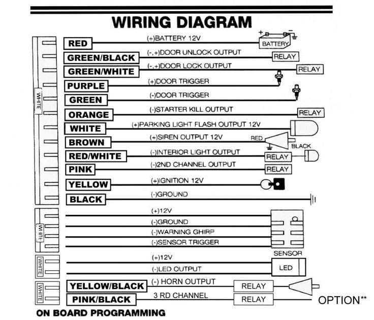
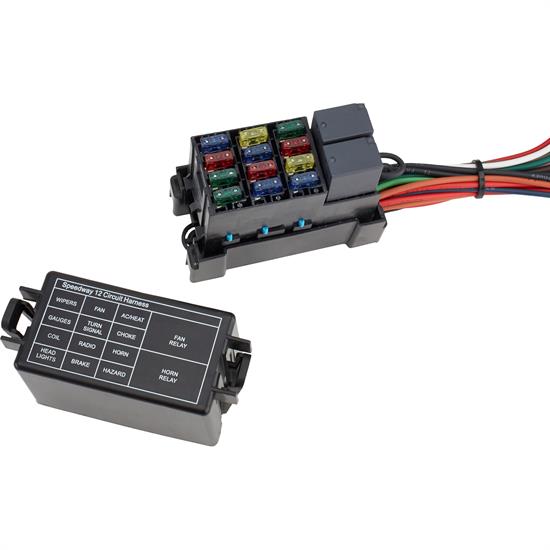
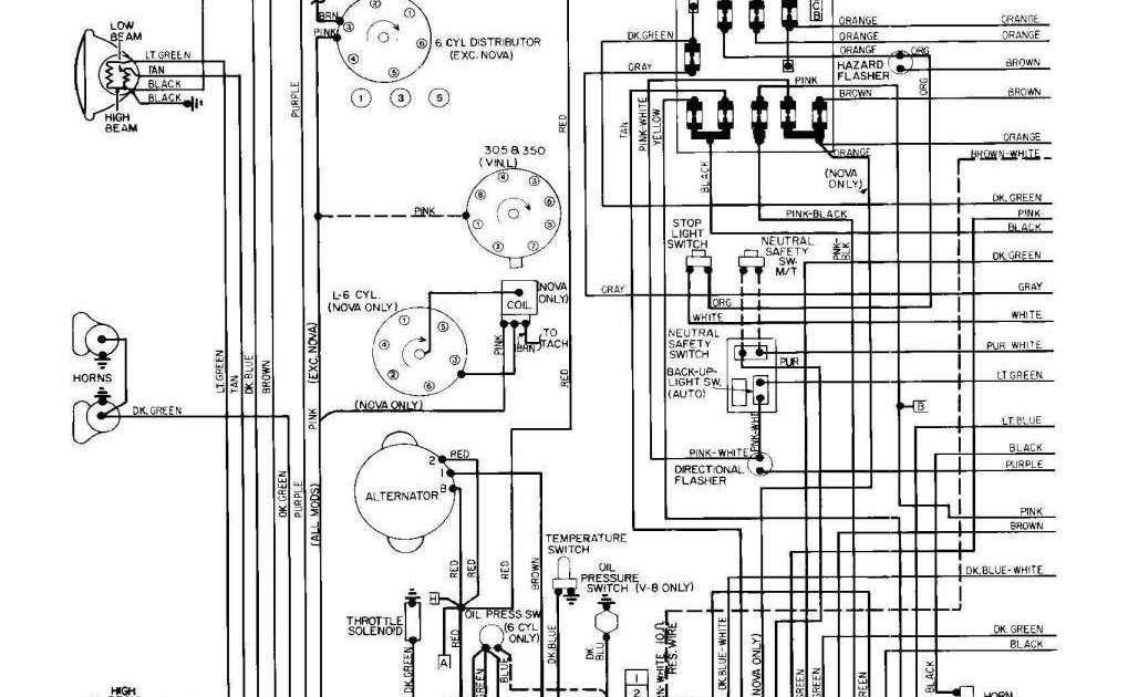
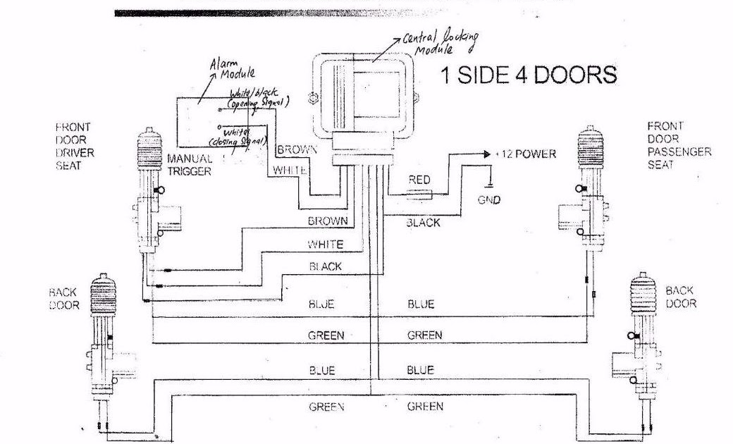
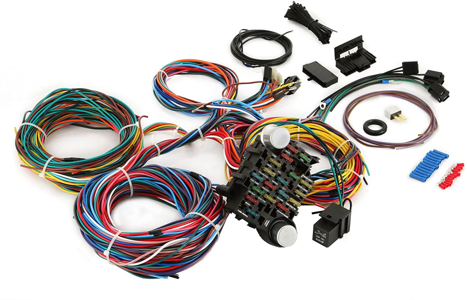
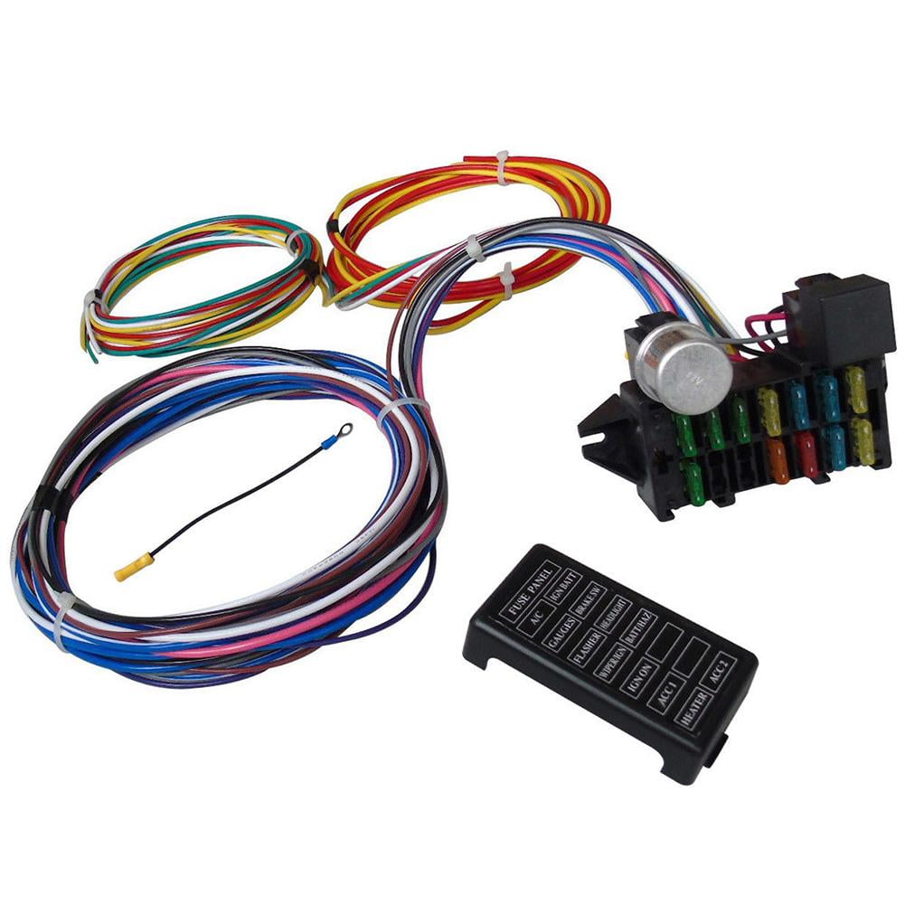
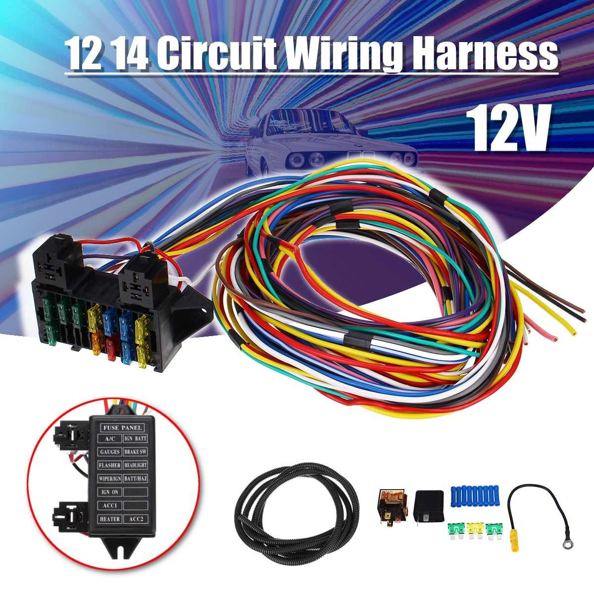
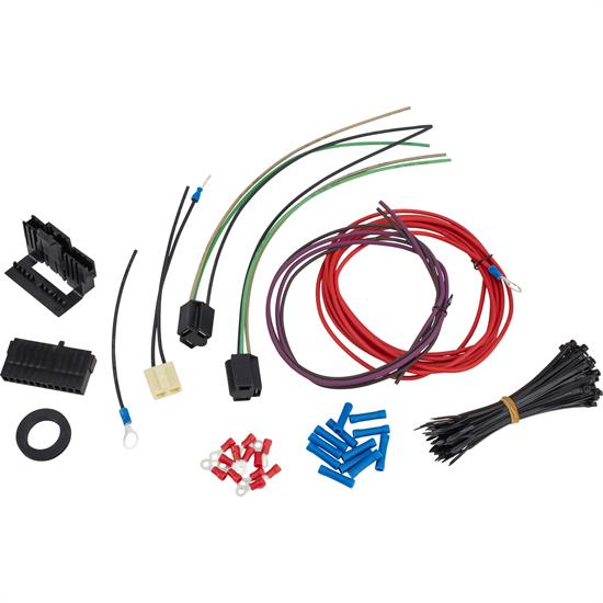
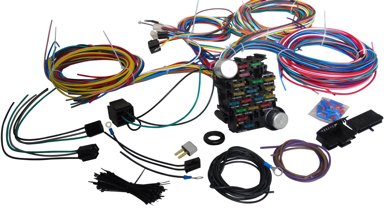
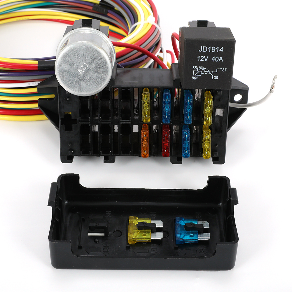
 Title : Speedway 12 Circuit Universal Muscle Car Wiring Harness W Wiring Diagram
Category : Wiring Diagram
Format : PDF
Title : Speedway 12 Circuit Universal Muscle Car Wiring Harness W Wiring Diagram
Category : Wiring Diagram
Format : PDF

.jpg)


.jpg?x-oss-process=image/auto-orient,1/quality,q_70/resize,m_mfit,w_1000,h_1000)


.jpg)
.jpg)
.jpg)
.jpg)
.jpg)

.jpg)


.jpg)