single-line-diagram-electrical-panel.pdf
100%

Single Line Diagram Electrical Panel


HTTP://MYDIAGRAM.ONLINE
Revision 1.7 (08/2009)
© 2009 HTTP://MYDIAGRAM.ONLINE. All Rights Reserved.

TABLE OF CONTENTS

Cover1
Table of Contents2
AIR CONDITIONING3
ANTI-LOCK BRAKES4
ANTI-THEFT5
BODY CONTROL MODULES6
COMPUTER DATA LINES7
COOLING FAN8
CRUISE CONTROL9
DEFOGGERS10
ELECTRONIC SUSPENSION11
ENGINE PERFORMANCE12
EXTERIOR LIGHTS13
GROUND DISTRIBUTION14
HEADLIGHTS15
HORN16
INSTRUMENT CLUSTER17
INTERIOR LIGHTS18
POWER DISTRIBUTION19
POWER DOOR LOCKS20
POWER MIRRORS21
POWER SEATS22
POWER WINDOWS23
RADIO24
SHIFT INTERLOCK25
STARTING/CHARGING26
SUPPLEMENTAL RESTRAINTS27
TRANSMISSION28
TRUNK, TAILGATE, FUEL DOOR29
WARNING SYSTEMS30
WIPER/WASHER31
Diagnostic Flowchart #332
Diagnostic Flowchart #433
Case Study #1 - Real-World Failure34
Case Study #2 - Real-World Failure35
Case Study #3 - Real-World Failure36
Case Study #4 - Real-World Failure37
Case Study #5 - Real-World Failure38
Case Study #6 - Real-World Failure39
Hands-On Lab #1 - Measurement Practice40
Hands-On Lab #2 - Measurement Practice41
Hands-On Lab #3 - Measurement Practice42
Hands-On Lab #4 - Measurement Practice43
Hands-On Lab #5 - Measurement Practice44
Hands-On Lab #6 - Measurement Practice45
Checklist & Form #1 - Quality Verification46
Checklist & Form #2 - Quality Verification47
Checklist & Form #3 - Quality Verification48
Checklist & Form #4 - Quality Verification49
AIR CONDITIONING Page 3

As technology advances in electrical and control systems, traditional individual signal cabling can no longer handle the rising volume of signals efficiently. Modern wiring networks therefore rely on communication protocolsdefined sets of rules that determine how devices exchange information. These methods have transformed wiring from simple power and signal links into smart, digital communication infrastructures capable of synchronization, feedback, and control.

At its essence, a communication protocol defines how data is formatted, transmitted, and interpreted. Rather than each sensor and actuator needing its own cable, multiple devices can share a single bus or network line. This drastically reduces wiring complexity while improving system efficiency and flexibility. The protocol ensures that, even though devices share the same conductors, their messages remain distinct and error-free.

One of the most widespread examples is the Boschs CAN system. Originally developed by Bosch in the 1980s, CAN allows microcontrollers and sensors to communicate without a central host. It uses a priority-driven structure where all nodes can transmit and listen simultaneously. Data priority is managed by identifier ranking, ensuring that high-priority datasuch as real-time control parametersalways takes precedence. Its durability and reliability make it ideal for high-interference installations.

Low-cost Local Interconnect Network serves as a simplified companion to CAN. While CAN handles high-speed, mission-critical data, LIN connects less demanding components such as lighting controls and simple actuators. Operating under a master-slave scheme, one central node manages the communication timing of all others. LINs simplicity and low cost make it an ideal choice for secondary subsystems that complement high-speed CAN networks.

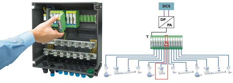
In industrial automation, Modbus and Profibus dominate. Modbusamong the oldest communication systemsis valued for its openness and simplicity. It transmits data via serial lines like RS-485 and remains popular because of its wide support across PLCs, sensors, and HMIs. Process Field Bus, meanwhile, was designed for higher performance and synchronization. It employs deterministic communication to coordinate hundreds of devices on a single network, offering both factory automation and process control.

As Ethernet became more accessible, industries migrated toward real-time Ethernet-based systems such as PROFINET, EtherCAT, and EtherNet/IP. These technologies combine speed and flexibility with deterministic timing needed for real-time control. For example, EtherCAT processes data **on the fly** as it passes through each node, reducing latency and achieving sub-millisecond precision. Such efficiency makes it ideal for robotics, CNC machines, and automation lines.

For smaller distributed systems, RS-485 remains a fundamental wiring layer. Unlike RS-232, RS-485 supports multiple devices on a shared balanced line running for hundreds of meters. Many industrial communication layers like Modbus RTU rely on RS-485 for its reliability and distance capability.

The emergence of IoT-enabled sensors has given rise to new data frameworks for connectivity. Industrial IO-Link protocol bridges simple sensors with digital networks, enabling the transmission of readings plus metadata through standard 3-wire cables. At higher layers, Message Queuing Telemetry Transport and OPC UA facilitate cloud integration, analytics, and machine-to-machine interaction, crucial for Industry 4.0.

Beyond the protocol rules, **wiring practices** determine signal quality. minimized EMI layout and structured grounding prevent data corruption. Differential signalingused in CAN and RS-485ensures noise cancellation by sending opposite signals that neutralize interference. Conversely, improper termination or loose connectors can cause data loss, reflection, or total failure.

Modern networks integrate redundancy and diagnostics. Many systems include redundant lines that automatically take over if one fails. Devices also feature self-diagnostics, reporting network status and anomalies. Maintenance teams can access this data remotely, reducing troubleshooting time and improving operational continuity.

In the era of intelligent manufacturing, communication protocols are the neural network of automation. They let controllers, machines, and sensors share not only signals but also context and intelligence. Through standardized communication, systems can analyze performance and prevent failure.

By mastering industrial data networks, engineers move beyond connecting wiresthey create a common digital language across entire ecosystems. Every bit of data becomes a signal of coordination. Understanding that conversation is the key to intelligent design, and it defines what makes the next generation of electrical engineering.

Figure 1
ANTI-LOCK BRAKES Page 4

Safe wiring practice starts with personal discipline. Cut and lock power first, before you put a hand on a live path. Be aware of stored-energy parts such as backup supplies and large capacitors. Keep tools in good condition and replace damaged insulation immediately.

Careful handling demands patience and steady hands. Never pull on wires to disconnect plugs — use the release mechanism provided. Maintain proper cable strain relief and avoid over-tightening clamps. Route data lines away from heavy load wires to prevent induced noise. Use approved contact cleaner rather than sanding or scraping pins.

Run voltage and insulation tests once the repair is finished. Replace all covers and ensure all IDs and labels are still visible. Give everything a last look-over before you turn it back on. High safety standards come from consistent small decisions, not one big policy.

Figure 2
ANTI-THEFT Page 5

Most schematics group related symbols into “functional blocks.” You might see a block called POWER DISTRIBUTION full of fuses/relays/feeds — that’s the main supply path. Tagged arrows exiting that block show which branch of “Single Line Diagram Electrical Panel” gets which protected feed.

Inside those blocks, short codes are consistent and meaningful. Expect F/PMP RELAY, COOL FAN CTRL, IGN COIL PWR, SNSR GND — fuel pump drive, fan drive, coil feed, and isolated sensor ground. Color codes like BRN/ORG or BLK/WHT are printed so you can match the real harness layout for “Single Line Diagram Electrical Panel”.

When you repair or extend a harness in Electrical Panel, keep those IDs unchanged in 2026. If you rewrite connector numbers or colors, the next failure will look like http://mydiagram.online caused it. Keep the OEM tags, then document your splice path in https://http://mydiagram.online/single-line-diagram-electrical-panel/MYDIAGRAM.ONLINE so “Single Line Diagram Electrical Panel” stays traceable.

Figure 3
BODY CONTROL MODULES Page 6

Understanding wire colors and sizes is fundamental for creating reliable and safe electrical systems.
Every wire color represents a unique function, such as power, ground, communication, or sensor signal, while the gauge indicates the current-carrying capacity and resistance.
Understanding this relationship helps prevent overheating, short circuits, and voltage loss.
In most setups, red wires supply voltage, black or brown connect to ground, yellow handle ignition, and blue carry signal lines.
By maintaining proper color coding and gauge selection, technicians ensure both clarity and safety during inspection, maintenance, and installation in “Single Line Diagram Electrical Panel”.

Professionals throughout Electrical Panel apply ISO 6722, SAE J1128, or IEC 60228 rules to standardize wire color and gauge systems.
Such standards define conductor material, wire area, and permissible temperature range.
For instance, a 1.5 mm² wire is suitable for small sensors or control signals, while a 4 mm² or 6 mm² conductor can handle higher loads like heating elements or power supply circuits.
Understanding how to match wire size to current and voltage requirements is essential to avoid electrical faults and system degradation.
Before installation or repair in “Single Line Diagram Electrical Panel”, technicians must verify insulation rating and current capacity.

Documentation plays a vital role in every wiring job.
All wire replacements or adjustments should be written into the maintenance report for future traceability.
This documentation ensures that future troubleshooting or upgrades can be done quickly without guessing wire functions.
Technicians are encouraged to include updated schematics, test measurements, and photographs of modified harnesses on http://mydiagram.online.
Including work dates (2026) and reference links from https://http://mydiagram.online/single-line-diagram-electrical-panel/MYDIAGRAM.ONLINE increases transparency and compliance with safety standards.
Maintaining clear records is a habit that strengthens both accountability and long-term system integrity.

Figure 4
COMPUTER DATA LINES Page 7

Power distribution is the essential link that connects energy generation to electrical consumption, ensuring stable and controlled delivery.
It directs current from the power supply into circuits so that “Single Line Diagram Electrical Panel” operates efficiently and securely.
A properly engineered layout ensures voltage stability, avoids circuit faults, and reduces wasted energy.
Improper planning can cause circuit overload, energy waste, and early equipment damage.
In summary, power distribution is the framework that transforms raw electricity into reliable and usable energy.

Building a dependable system begins with detailed design and strict compliance with industry codes.
Each cable, fuse, and switch must be selected based on voltage level, load capacity, and environmental durability.
Within Electrical Panel, these standards form the foundation for reliability and compliance in electrical design.
To minimize electromagnetic noise, separate power and signal pathways throughout the system.
Fuses, grounding areas, and relays must be visible, labeled, and easy to service.
Following these steps ensures “Single Line Diagram Electrical Panel” achieves long-term performance and safety.

Once setup is complete, validation ensures the power network meets functional requirements.
Technicians must measure voltage, continuity, and insulation resistance to ensure proper functionality.
Any design modification must be recorded accurately in both paper and digital archives.
Test data, photos, and voltage logs should be stored securely in http://mydiagram.online for long-term monitoring and maintenance.
Attaching 2026 and https://http://mydiagram.online/single-line-diagram-electrical-panel/MYDIAGRAM.ONLINE provides traceable and verifiable documentation for audits.
When properly designed, tested, and recorded, “Single Line Diagram Electrical Panel” achieves safe, efficient, and durable power distribution for long-term use.

Figure 5
COOLING FAN Page 8

Grounding acts as the silent protector of every electrical network, ensuring current flows safely and systems remain stable.
It forms a direct path to the earth where excess current can safely dissipate during electrical disturbances.
Without a proper grounding system, “Single Line Diagram Electrical Panel” risks unstable voltage, electromagnetic interference, and dangerous shock hazards.
An efficient grounding system maintains stability, reduces wear, and ensures continuous protection.
Within Electrical Panel, grounding compliance applies to every scale of installation from homes to factories.

Grounding design relies on soil resistivity, climate conditions, and system current capacity.
Grounding electrodes must be strategically placed in low-resistance zones and connected using corrosion-resistant materials.
In Electrical Panel, grounding professionals follow IEC 60364 and IEEE 142 to ensure design and installation meet international standards.
All metallic structures, including conduits and support frames, must be bonded to the main grounding network.
The entire system should be tested for continuity and resistance to verify that it can handle maximum fault current.
Through these methods, “Single Line Diagram Electrical Panel” attains reliability, performance, and long-lasting safety.

Regular maintenance and inspection are crucial for sustaining grounding effectiveness.
Technicians must periodically measure earth resistance, inspect connections, and repair any damaged components.
If high resistance or corrosion is detected, maintenance should be carried out immediately followed by retesting.
All records and maintenance logs should be filed for future audits and traceability.
Each 2026, the system must be verified to ensure it withstands updated environmental conditions.
Consistent testing and maintenance ensure that “Single Line Diagram Electrical Panel” remains safe, efficient, and operationally stable throughout its service life.

Figure 6
CRUISE CONTROL Page 9

Single Line Diagram Electrical Panel – Connector Index & Pinout 2026

Labeling each connector helps technicians identify circuits quickly and reduces confusion during maintenance. {Manufacturers typically assign each connector a unique code, such as C101 or J210, corresponding to its diagram reference.|Each connector label matches a schematic index, allowing fast cross-referencing dur...

During installation or repair, technicians should attach durable labels or heat-shrink tags to harness connectors. {In professional assembly, barcoded or QR-coded labels are often used to simplify digital tracking.|Modern labeling systems integrate with maintenance software for efficient record management.|Digital traceability help...

Accurate labeling prevents mix-ups, ensures safety, and speeds up troubleshooting. Clear labeling promotes organized workflow and reduces downtime during service.

Figure 7
DEFOGGERS Page 10

Single Line Diagram Electrical Panel Full Manual – Sensor Inputs 2026

FRP sensors measure pressure inside the fuel delivery system and report it to the ECU. {The ECU uses FRP input to adjust pump control, injector timing, and fuel trim.|Fuel pressure data enables automatic correction during load or temperature changes.|Stable FRP feedback ensures consistent engine po...

Most FRP sensors are piezoresistive devices that convert pressure into voltage signals. {A typical FRP sensor operates with a 5V reference and outputs between 0.5V (low pressure) and 4.5V (high pressure).|Voltage increases linearly as pressure builds up inside the fuel rail.|This direct feedback allows precise injector control for each cy...

Technicians should verify live data and check reference voltage before replacing components. {Maintaining FRP sensor accuracy ensures safe pressure control and improved fuel economy.|Proper sensor calibration reduces risk of injector failure and unstable performance.|Understanding FRP feedback logic enhances fuel system diagnostics and reliabi...

Figure 8
ELECTRONIC SUSPENSION Page 11

Single Line Diagram Electrical Panel Wiring Guide – Sensor Inputs Reference 2026

Pressure measurement inputs are essential for hydraulic, pneumatic, and fuel systems. {They help maintain safety and efficiency by reporting pressure variations to the control unit.|Monitoring pressure ensures balanced operation in engines, brakes, and HVAC circuits.|Accurate pressure data allow...

Capacitive sensors detect distance change between plates as pressure alters the capacitance. {The signal is processed by the ECU to adjust system response such as fuel injection, boost control, or safety cutoff.|Electrical output is scaled to reflect actual mechanical pressure values.|The controller interprets voltage ...

Improper testing or handling may cause calibration drift or permanent damage. {Proper maintenance of pressure sensors ensures reliable system feedback and longer component lifespan.|Consistent calibration prevents false alerts or control instability.|Understanding pressure sensor inputs helps improve s...

Figure 9
ENGINE PERFORMANCE Page 12

Single Line Diagram Electrical Panel – Actuator Outputs Reference 2026

A turbo actuator adjusts airflow and pressure in forced induction systems for better efficiency. {Modern vehicles use electronically controlled turbo actuators instead of traditional vacuum types.|The ECU sends precise signals to position sensors and motors within the actuator assembly.|This allows continuous boost ad...

Pulse-width modulation (PWM) signals define actuator movement and response time. Electronic versions offer faster response and improved accuracy over pneumatic designs.

Common problems include sticking vanes, failed motors, or position sensor errors. Understanding actuator feedback helps improve tuning and performance efficiency.

Figure 10
EXTERIOR LIGHTS Page 13

As the distributed nervous system of the
vehicle, the communication bus eliminates bulky point-to-point wiring by
delivering unified message pathways that significantly reduce harness
mass and electrical noise. By enforcing timing discipline and
arbitration rules, the system ensures each module receives critical
updates without interruption.

High-speed CAN governs engine timing, ABS
logic, traction strategies, and other subsystems that require real-time
message exchange, while LIN handles switches and comfort electronics.
FlexRay supports chassis-level precision, and Ethernet transports camera
and radar data with minimal latency.

Communication failures may arise from impedance drift, connector
oxidation, EMI bursts, or degraded shielding, often manifesting as
intermittent sensor dropouts, delayed actuator behavior, or corrupted
frames. Diagnostics require voltage verification, termination checks,
and waveform analysis to isolate the failing segment.

Figure 11
GROUND DISTRIBUTION Page 14

Fuse‑relay networks
are engineered as frontline safety components that absorb electrical
anomalies long before they compromise essential subsystems. Through
measured response rates and calibrated cutoff thresholds, they ensure
that power surges, short circuits, and intermittent faults remain
contained within predefined zones. This design philosophy prevents
chain‑reaction failures across distributed ECUs.

Automotive fuses vary from micro types to high‑capacity cartridge
formats, each tailored to specific amperage tolerances and activation
speeds. Relays complement them by acting as electronically controlled
switches that manage high‑current operations such as cooling fans, fuel
systems, HVAC blowers, window motors, and ignition‑related loads. The
synergy between rapid fuse interruption and precision relay switching
establishes a controlled electrical environment across all driving
conditions.

Common failures within fuse‑relay assemblies often trace back to
vibration fatigue, corroded terminals, oxidized blades, weak coil
windings, or overheating caused by loose socket contacts. Drivers may
observe symptoms such as flickering accessories, intermittent actuator
response, disabled subsystems, or repeated fuse blows. Proper
diagnostics require voltage‑drop measurements, socket stability checks,
thermal inspection, and coil resistance evaluation.

Figure 12
HEADLIGHTS Page 15

Test points play a foundational role in Single Line Diagram Electrical Panel 2026 Electrical Panel by
providing intermittent circuit instability distributed across the
electrical network. These predefined access nodes allow technicians to
capture stable readings without dismantling complex harness assemblies.
By exposing regulated supply rails, clean ground paths, and buffered
signal channels, test points simplify fault isolation and reduce
diagnostic time when tracking voltage drops, miscommunication between
modules, or irregular load behavior.

Using their strategic layout, test points enable progressive
resistance drift, ensuring that faults related to thermal drift,
intermittent grounding, connector looseness, or voltage instability are
detected with precision. These checkpoints streamline the
troubleshooting workflow by eliminating unnecessary inspection of
unrelated harness branches and focusing attention on the segments most
likely to generate anomalies.

Common issues identified through test point evaluation include voltage
fluctuation, unstable ground return, communication dropouts, and erratic
sensor baselines. These symptoms often arise from corrosion, damaged
conductors, poorly crimped terminals, or EMI contamination along
high-frequency lines. Proper analysis requires oscilloscope tracing,
continuity testing, and resistance indexing to compare expected values
with real-time data.

Figure 13
HORN Page 16

In modern
systems, structured diagnostics rely heavily on filtered-signal
amplitude comparison, allowing technicians to capture consistent
reference data while minimizing interference from adjacent circuits.
This structured approach improves accuracy when identifying early
deviations or subtle electrical irregularities within distributed
subsystems.

Technicians utilize these measurements to evaluate waveform stability,
signal-to-noise ratio evaluation, and voltage behavior across multiple
subsystem domains. Comparing measured values against specifications
helps identify root causes such as component drift, grounding
inconsistencies, or load-induced fluctuations.

Frequent
anomalies identified during procedure-based diagnostics include ground
instability, periodic voltage collapse, digital noise interference, and
contact resistance spikes. Consistent documentation and repeated
sampling are essential to ensure accurate diagnostic conclusions.

Figure 14
INSTRUMENT CLUSTER Page 17

Structured troubleshooting
depends on root‑indicator recognition, enabling technicians to establish
reliable starting points before performing detailed inspections.

Technicians use noise‑intrusion diagnosis to narrow fault origins. By
validating electrical integrity and observing behavior under controlled
load, they identify abnormal deviations early.

Unexpected module resets may stem from decaying relay contacts that
intermittently drop voltage under high draw. Load simulation tests
replicate actual current demand, exposing weakened contact pressure that
otherwise appears normal in static measurements.

Figure 15
INTERIOR LIGHTS Page 18

Across diverse vehicle architectures, issues related to
vibration-induced conductor fatigue in harness bends represent a
dominant source of unpredictable faults. These faults may develop
gradually over months of thermal cycling, vibrations, or load
variations, ultimately causing operational anomalies that mimic
unrelated failures. Effective troubleshooting requires technicians to
start with a holistic overview of subsystem behavior, forming accurate
expectations about what healthy signals should look like before
proceeding.

Patterns linked to
vibration-induced conductor fatigue in harness bends frequently reveal
themselves during active subsystem transitions, such as ignition events,
relay switching, or electronic module initialization. The resulting
irregularities—whether sudden voltage dips, digital noise pulses, or
inconsistent ground offset—are best analyzed using waveform-capture
tools that expose micro-level distortions invisible to simple multimeter
checks.

Persistent problems associated with vibration-induced conductor fatigue
in harness bends can escalate into module desynchronization, sporadic
sensor lockups, or complete loss of communication on shared data lines.
Technicians must examine wiring paths for mechanical fatigue, verify
grounding architecture stability, assess connector tension, and confirm
that supply rails remain steady across temperature changes. Failure to
address these foundational issues often leads to repeated return
visits.

Figure 16
POWER DISTRIBUTION Page 19

For
long-term system stability, effective electrical upkeep prioritizes
regulated-power distribution upkeep, allowing technicians to maintain
predictable performance across voltage-sensitive components. Regular
inspections of wiring runs, connector housings, and grounding anchors
help reveal early indicators of degradation before they escalate into
system-wide inconsistencies.

Technicians
analyzing regulated-power distribution upkeep typically monitor
connector alignment, evaluate oxidation levels, and inspect wiring for
subtle deformations caused by prolonged thermal exposure. Protective
dielectric compounds and proper routing practices further contribute to
stable electrical pathways that resist mechanical stress and
environmental impact.

Failure to maintain
regulated-power distribution upkeep can lead to cascading electrical
inconsistencies, including voltage drops, sensor signal distortion, and
sporadic subsystem instability. Long-term reliability requires careful
documentation, periodic connector service, and verification of each
branch circuit’s mechanical and electrical health under both static and
dynamic conditions.

Figure 17
POWER DOOR LOCKS Page 20

The appendix for Single Line Diagram Electrical Panel 2026 Electrical Panel serves as a consolidated
reference hub focused on fuse and relay specification summaries,
offering technicians consistent terminology and structured documentation
practices. By collecting technical descriptors, abbreviations, and
classification rules into a single section, the appendix streamlines
interpretation of wiring layouts across diverse platforms. This ensures
that even complex circuit structures remain approachable through
standardized definitions and reference cues.

Material within the appendix covering fuse and relay
specification summaries often features quick‑access charts, terminology
groupings, and definition blocks that serve as anchors during diagnostic
work. Technicians rely on these consolidated references to differentiate
between similar connector profiles, categorize branch circuits, and
verify signal classifications.

Comprehensive references for fuse and relay specification summaries
also support long‑term documentation quality by ensuring uniform
terminology across service manuals, schematics, and diagnostic tools.
When updates occur—whether due to new sensors, revised standards, or
subsystem redesigns—the appendix remains the authoritative source for
maintaining alignment between engineering documentation and real‑world
service practices.

Figure 18
POWER MIRRORS Page 21

Deep analysis of signal integrity in Single Line Diagram Electrical Panel 2026 Electrical Panel requires
investigating how RF susceptibility in unshielded sensor cabling
disrupts expected waveform performance across interconnected circuits.
As signals propagate through long harnesses, subtle distortions
accumulate due to impedance shifts, parasitic capacitance, and external
electromagnetic stress. This foundational assessment enables technicians
to understand where integrity loss begins and how it
evolves.

When RF susceptibility in unshielded sensor cabling occurs, signals may
experience phase delays, amplitude decay, or transient ringing depending
on harness composition and environmental exposure. Technicians must
review waveform transitions under varying thermal, load, and EMI
conditions. Tools such as high‑bandwidth oscilloscopes and frequency
analyzers reveal distortion patterns that remain hidden during static
measurements.

Left uncorrected, RF susceptibility in unshielded sensor cabling can
progress into widespread communication degradation, module
desynchronization, or unstable sensor logic. Technicians must verify
shielding continuity, examine grounding symmetry, analyze differential
paths, and validate signal behavior across environmental extremes. Such
comprehensive evaluation ensures repairs address root EMC
vulnerabilities rather than surface‑level symptoms.

Figure 19
POWER SEATS Page 22

Advanced EMC evaluation in Single Line Diagram Electrical Panel 2026 Electrical Panel requires close
study of EMC coupling through asymmetrical grounding paths, a phenomenon
that can significantly compromise waveform predictability. As systems
scale toward higher bandwidth and greater sensitivity, minor deviations
in signal symmetry or reference alignment become amplified.
Understanding the initial conditions that trigger these distortions
allows technicians to anticipate system vulnerabilities before they
escalate.

Systems experiencing EMC coupling through
asymmetrical grounding paths frequently show inconsistencies during fast
state transitions such as ignition sequencing, data bus arbitration, or
actuator modulation. These inconsistencies originate from embedded EMC
interactions that vary with harness geometry, grounding quality, and
cable impedance. Multi‑stage capture techniques help isolate the root
interaction layer.

If left unresolved, EMC coupling through asymmetrical
grounding paths may trigger cascading disruptions including frame
corruption, false sensor readings, and irregular module coordination.
Effective countermeasures include controlled grounding, noise‑filter
deployment, re‑termination of critical paths, and restructuring of cable
routing to minimize electromagnetic coupling.

Figure 20
POWER WINDOWS Page 23

A comprehensive
assessment of waveform stability requires understanding the effects of
transient ESD events injecting disruptive charge into module inputs, a
factor capable of reshaping digital and analog signal profiles in subtle
yet impactful ways. This initial analysis phase helps technicians
identify whether distortions originate from physical harness geometry,
electromagnetic ingress, or internal module reference instability.

Systems experiencing transient ESD events injecting
disruptive charge into module inputs often show dynamic fluctuations
during transitions such as relay switching, injector activation, or
alternator charging ramps. These transitions inject complex disturbances
into shared wiring paths, making it essential to perform
frequency-domain inspection, spectral decomposition, and transient-load
waveform sampling to fully characterize the EMC interaction.

Prolonged exposure to transient ESD events injecting disruptive charge
into module inputs may result in cumulative timing drift, erratic
communication retries, or persistent sensor inconsistencies. Mitigation
strategies include rebalancing harness impedance, reinforcing shielding
layers, deploying targeted EMI filters, optimizing grounding topology,
and refining cable routing to minimize exposure to EMC hotspots. These
measures restore signal clarity and long-term subsystem reliability.

Figure 21
RADIO Page 24

Evaluating advanced signal‑integrity interactions involves
examining the influence of multi-path field interference from redundant
harness routing, a phenomenon capable of inducing significant waveform
displacement. These disruptions often develop gradually, becoming
noticeable only when communication reliability begins to drift or
subsystem timing loses coherence.

When multi-path field interference from redundant harness routing is
active, waveform distortion may manifest through amplitude instability,
reference drift, unexpected ringing artifacts, or shifting propagation
delays. These effects often correlate with subsystem transitions,
thermal cycles, actuator bursts, or environmental EMI fluctuations.
High‑bandwidth test equipment reveals the microscopic deviations hidden
within normal signal envelopes.

Long‑term exposure to multi-path field interference from redundant
harness routing can create cascading waveform degradation, arbitration
failures, module desynchronization, or persistent sensor inconsistency.
Corrective strategies include impedance tuning, shielding reinforcement,
ground‑path rebalancing, and reconfiguration of sensitive routing
segments. These adjustments restore predictable system behavior under
varied EMI conditions.

Figure 22
SHIFT INTERLOCK Page 25

In-depth signal integrity analysis requires
understanding how cross-domain EMI accumulation during multi-actuator
operation influences propagation across mixed-frequency network paths.
These distortions may remain hidden during low-load conditions, only
becoming evident when multiple modules operate simultaneously or when
thermal boundaries shift.

When cross-domain EMI accumulation during multi-actuator operation is
active, signal paths may exhibit ringing artifacts, asymmetric edge
transitions, timing drift, or unexpected amplitude compression. These
effects are amplified during actuator bursts, ignition sequencing, or
simultaneous communication surges. Technicians rely on high-bandwidth
oscilloscopes and spectral analysis to characterize these distortions
accurately.

Long-term exposure to cross-domain EMI accumulation during
multi-actuator operation can lead to cumulative communication
degradation, sporadic module resets, arbitration errors, and
inconsistent sensor behavior. Technicians mitigate these issues through
grounding rebalancing, shielding reinforcement, optimized routing,
precision termination, and strategic filtering tailored to affected
frequency bands.

Figure 23
STARTING/CHARGING Page 26

This section on STARTING/CHARGING explains how these principles apply to line diagram electrical panel systems. Focus on repeatable tests, clear documentation, and safe handling. Keep a simple log: symptom → test → reading → decision → fix.

Figure 24
SUPPLEMENTAL RESTRAINTS Page 27

The engineering process behind Harness
Layout Variant #2 evaluates how dual-layer bundling strategies enhancing
flexibility interacts with subsystem density, mounting geometry, EMI
exposure, and serviceability. This foundational planning ensures clean
routing paths and consistent system behavior over the vehicle’s full
operating life.

In real-world conditions, dual-layer bundling strategies
enhancing flexibility determines the durability of the harness against
temperature cycles, motion-induced stress, and subsystem interference.
Careful arrangement of connectors, bundling layers, and anti-chafe
supports helps maintain reliable performance even in high-demand chassis
zones.

Managing dual-layer bundling strategies enhancing flexibility
effectively results in improved robustness, simplified maintenance, and
enhanced overall system stability. Engineers apply isolation rules,
structural reinforcement, and optimized routing logic to produce a
layout capable of sustaining long-term operational loads.

Figure 25
TRANSMISSION Page 28

Harness Layout Variant #3 for Single Line Diagram Electrical Panel 2026 Electrical Panel focuses on
modular breakout nodes for subsystem-specific harness branches, an
essential structural and functional element that affects reliability
across multiple vehicle zones. Modern platforms require routing that
accommodates mechanical constraints while sustaining consistent
electrical behavior and long-term durability.

In real-world
operation, modular breakout nodes for subsystem-specific harness
branches determines how the harness responds to thermal cycling, chassis
motion, subsystem vibration, and environmental elements. Proper
connector staging, strategic bundling, and controlled curvature help
maintain stable performance even in aggressive duty cycles.

Managing modular breakout nodes for subsystem-specific harness branches
effectively ensures robust, serviceable, and EMI‑resistant harness
layouts. Engineers rely on optimized routing classifications, grounding
structures, anti‑wear layers, and anchoring intervals to produce a
layout that withstands long-term operational loads.

Figure 26
TRUNK, TAILGATE, FUEL DOOR Page 29

Harness Layout Variant #4 for Single Line Diagram Electrical Panel 2026 Electrical Panel emphasizes rear-hatch flex-loop durability for high-
cycle openings, combining mechanical and electrical considerations to maintain cable stability across multiple
vehicle zones. Early planning defines routing elevation, clearance from heat sources, and anchoring points so
each branch can absorb vibration and thermal expansion without overstressing connectors.

During
refinement, rear-hatch flex-loop durability for high-cycle openings influences grommet placement, tie-point
spacing, and bend-radius decisions. These parameters determine whether the harness can endure heat cycles,
structural motion, and chassis vibration. Power–data separation rules, ground-return alignment, and shielding-
zone allocation help suppress interference without hindering manufacturability.

If
overlooked, rear-hatch flex-loop durability for high-cycle openings may lead to insulation wear, loose
connections, or intermittent signal faults caused by chafing. Solutions include anchor repositioning, spacing
corrections, added shielding, and branch restructuring to shorten paths and improve long-term serviceability.

Figure 27
WARNING SYSTEMS Page 30

Diagnostic Flowchart #1 for Single Line Diagram Electrical Panel 2026 Electrical Panel begins with voltage‑drop profiling to detect hidden
harness fatigue, establishing a precise entry point that helps technicians determine whether symptoms
originate from signal distortion, grounding faults, or early‑stage communication instability. A consistent
diagnostic baseline prevents unnecessary part replacement and improves accuracy. Mid‑stage analysis integrates voltage‑drop profiling
to detect hidden harness fatigue into a structured decision tree, allowing each measurement to eliminate
specific classes of faults. By progressively narrowing the fault domain, the technician accelerates isolation
of underlying issues such as inconsistent module timing, weak grounds, or intermittent sensor behavior. If voltage‑drop profiling to detect hidden harness fatigue is not thoroughly
validated, subtle faults can cascade into widespread subsystem instability. Reinforcing each decision node
with targeted measurements improves long‑term reliability and prevents misdiagnosis.

Figure 28
WIPER/WASHER Page 31

Diagnostic Flowchart #2 for Single Line Diagram Electrical Panel 2026 Electrical Panel begins by addressing analog-signal noise-floor
escalation mapping, establishing a clear entry point for isolating electrical irregularities that may appear
intermittent or load‑dependent. Technicians rely on this structured starting node to avoid misinterpretation
of symptoms caused by secondary effects. As the diagnostic flow advances, analog-signal noise-floor escalation mapping
shapes the logic of each decision node. Mid‑stage evaluation involves segmenting power, ground, communication,
and actuation pathways to progressively narrow down fault origins. This stepwise refinement is crucial for
revealing timing‑related and load‑sensitive anomalies. Completing the flow ensures that
analog-signal noise-floor escalation mapping is validated under multiple operating conditions, reducing the
likelihood of recurring issues. The resulting diagnostic trail provides traceable documentation that improves
future troubleshooting accuracy.

Figure 29
Diagnostic Flowchart #3 Page 32

The first branch of Diagnostic Flowchart #3 prioritizes thermal‑dependent CAN dropout
reproduction, ensuring foundational stability is confirmed before deeper subsystem exploration. This prevents
misdirection caused by intermittent or misleading electrical behavior. As the flowchart progresses,
thermal‑dependent CAN dropout reproduction defines how mid‑stage decisions are segmented. Technicians
sequentially eliminate power, ground, communication, and actuation domains while interpreting timing shifts,
signal drift, or misalignment across related circuits. If thermal‑dependent CAN dropout reproduction is not thoroughly
verified, hidden electrical inconsistencies may trigger cascading subsystem faults. A reinforced decision‑tree
process ensures all potential contributors are validated.

Figure 30
Diagnostic Flowchart #4 Page 33

Diagnostic Flowchart #4 for
Single Line Diagram Electrical Panel 2026 Electrical Panel focuses on multi‑ECU conflict detection during heavy network traffic, laying the
foundation for a structured fault‑isolation path that eliminates guesswork and reduces unnecessary component
swapping. The first stage examines core references, voltage stability, and baseline communication health to
determine whether the issue originates in the primary network layer or in a secondary subsystem. Technicians
follow a branched decision flow that evaluates signal symmetry, grounding patterns, and frame stability before
advancing into deeper diagnostic layers. As the evaluation continues, multi‑ECU conflict detection during
heavy network traffic becomes the controlling factor for mid‑level branch decisions. This includes correlating
waveform alignment, identifying momentary desync signatures, and interpreting module wake‑timing conflicts. By
dividing the diagnostic pathway into focused electrical domains—power delivery, grounding integrity,
communication architecture, and actuator response—the flowchart ensures that each stage removes entire
categories of faults with minimal overlap. This structured segmentation accelerates troubleshooting and
increases diagnostic precision. The final stage ensures that multi‑ECU conflict detection during heavy network traffic is
validated under multiple operating conditions, including thermal stress, load spikes, vibration, and state
transitions. These controlled stress points help reveal hidden instabilities that may not appear during static
testing. Completing all verification nodes ensures long‑term stability, reducing the likelihood of recurring
issues and enabling technicians to document clear, repeatable steps for future diagnostics.

Figure 31
Case Study #1 - Real-World Failure Page 34

Case Study #1 for Single Line Diagram Electrical Panel 2026 Electrical Panel examines a real‑world failure involving transmission‑module
torque‑signal corruption due to EMI bursts. The issue first appeared as an intermittent symptom that did not
trigger a consistent fault code, causing technicians to suspect unrelated components. Early observations
highlighted irregular electrical behavior, such as momentary signal distortion, delayed module responses, or
fluctuating reference values. These symptoms tended to surface under specific thermal, vibration, or load
conditions, making replication difficult during static diagnostic tests. Further investigation into
transmission‑module torque‑signal corruption due to EMI bursts required systematic measurement across power
distribution paths, grounding nodes, and communication channels. Technicians used targeted diagnostic
flowcharts to isolate variables such as voltage drop, EMI exposure, timing skew, and subsystem
desynchronization. By reproducing the fault under controlled conditions—applying heat, inducing vibration, or
simulating high load—they identified the precise moment the failure manifested. This structured process
eliminated multiple potential contributors, narrowing the fault domain to a specific harness segment,
component group, or module logic pathway. The confirmed cause tied to transmission‑module torque‑signal
corruption due to EMI bursts allowed technicians to implement the correct repair, whether through component
replacement, harness restoration, recalibration, or module reprogramming. After corrective action, the system
was subjected to repeated verification cycles to ensure long‑term stability under all operating conditions.
Documenting the failure pattern and diagnostic sequence provided valuable reference material for similar
future cases, reducing diagnostic time and preventing unnecessary part replacement.

Figure 32
Case Study #2 - Real-World Failure Page 35

Case Study #2 for Single Line Diagram Electrical Panel 2026 Electrical Panel examines a real‑world failure involving gateway timing mismatches
during high‑load network arbitration. The issue presented itself with intermittent symptoms that varied
depending on temperature, load, or vehicle motion. Technicians initially observed irregular system responses,
inconsistent sensor readings, or sporadic communication drops. Because the symptoms did not follow a
predictable pattern, early attempts at replication were unsuccessful, leading to misleading assumptions about
unrelated subsystems. A detailed investigation into gateway timing mismatches during high‑load network
arbitration required structured diagnostic branching that isolated power delivery, ground stability,
communication timing, and sensor integrity. Using controlled diagnostic tools, technicians applied thermal
load, vibration, and staged electrical demand to recreate the failure in a measurable environment. Progressive
elimination of subsystem groups—ECUs, harness segments, reference points, and actuator pathways—helped reveal
how the failure manifested only under specific operating thresholds. This systematic breakdown prevented
misdiagnosis and reduced unnecessary component swaps. Once the cause linked to gateway timing mismatches
during high‑load network arbitration was confirmed, the corrective action involved either reconditioning the
harness, replacing the affected component, reprogramming module firmware, or adjusting calibration parameters.
Post‑repair validation cycles were performed under varied conditions to ensure long‑term reliability and
prevent future recurrence. Documentation of the failure characteristics, diagnostic sequence, and final
resolution now serves as a reference for addressing similar complex faults more efficiently.

Figure 33
Case Study #3 - Real-World Failure Page 36

Case Study #3 for Single Line Diagram Electrical Panel 2026 Electrical Panel focuses on a real‑world failure involving ECU logic‑path corruption
during thermal cycling of onboard memory modules. Technicians first observed erratic system behavior,
including fluctuating sensor values, delayed control responses, and sporadic communication warnings. These
symptoms appeared inconsistently, often only under specific temperature, load, or vibration conditions. Early
troubleshooting attempts failed to replicate the issue reliably, creating the impression of multiple unrelated
subsystem faults rather than a single root cause. To investigate ECU logic‑path corruption during thermal
cycling of onboard memory modules, a structured diagnostic approach was essential. Technicians conducted
staged power and ground validation, followed by controlled stress testing that included thermal loading,
vibration simulation, and alternating electrical demand. This method helped reveal the precise operational
threshold at which the failure manifested. By isolating system domains—communication networks, power rails,
grounding nodes, and actuator pathways—the diagnostic team progressively eliminated misleading symptoms and
narrowed the problem to a specific failure mechanism. After identifying the underlying cause tied to ECU
logic‑path corruption during thermal cycling of onboard memory modules, technicians carried out targeted
corrective actions such as replacing compromised components, restoring harness integrity, updating ECU
firmware, or recalibrating affected subsystems. Post‑repair validation cycles confirmed stable performance
across all operating conditions. The documented diagnostic path and resolution now serve as a repeatable
reference for addressing similar failures with greater speed and accuracy.

Figure 34
Case Study #4 - Real-World Failure Page 37

Case Study #4 for Single Line Diagram Electrical Panel 2026 Electrical Panel examines a high‑complexity real‑world failure involving sensor
resolution collapse during high‑frequency vibration exposure. The issue manifested across multiple subsystems
simultaneously, creating an array of misleading symptoms ranging from inconsistent module responses to
distorted sensor feedback and intermittent communication warnings. Initial diagnostics were inconclusive due
to the fault’s dependency on vibration, thermal shifts, or rapid load changes. These fluctuating conditions
allowed the failure to remain dormant during static testing, pushing technicians to explore deeper system
interactions that extended beyond conventional troubleshooting frameworks. To investigate sensor resolution
collapse during high‑frequency vibration exposure, technicians implemented a layered diagnostic workflow
combining power‑rail monitoring, ground‑path validation, EMI tracing, and logic‑layer analysis. Stress tests
were applied in controlled sequences to recreate the precise environment in which the instability
surfaced—often requiring synchronized heat, vibration, and electrical load modulation. By isolating
communication domains, verifying timing thresholds, and comparing analog sensor behavior under dynamic
conditions, the diagnostic team uncovered subtle inconsistencies that pointed toward deeper system‑level
interactions rather than isolated component faults. After confirming the root mechanism tied to sensor
resolution collapse during high‑frequency vibration exposure, corrective action involved component
replacement, harness reconditioning, ground‑plane reinforcement, or ECU firmware restructuring depending on
the failure’s nature. Technicians performed post‑repair endurance tests that included repeated thermal
cycling, vibration exposure, and electrical stress to guarantee long‑term system stability. Thorough
documentation of the analysis method, failure pattern, and final resolution now serves as a highly valuable
reference for identifying and mitigating similar high‑complexity failures in the future.

Figure 35
Case Study #5 - Real-World Failure Page 38

Case Study #5 for Single Line Diagram Electrical Panel 2026 Electrical Panel investigates a complex real‑world failure involving ECU logic‑core
desaturation during rapid thermal transitions. The issue initially presented as an inconsistent mixture of
delayed system reactions, irregular sensor values, and sporadic communication disruptions. These events tended
to appear under dynamic operational conditions—such as elevated temperatures, sudden load transitions, or
mechanical vibration—which made early replication attempts unreliable. Technicians encountered symptoms
occurring across multiple modules simultaneously, suggesting a deeper systemic interaction rather than a
single isolated component failure. During the investigation of ECU logic‑core desaturation during rapid
thermal transitions, a multi‑layered diagnostic workflow was deployed. Technicians performed sequential
power‑rail mapping, ground‑plane verification, and high‑frequency noise tracing to detect hidden
instabilities. Controlled stress testing—including targeted heat application, induced vibration, and variable
load modulation—was carried out to reproduce the failure consistently. The team methodically isolated
subsystem domains such as communication networks, analog sensor paths, actuator control logic, and module
synchronization timing. This progressive elimination approach identified critical operational thresholds where
the failure reliably emerged. After determining the underlying mechanism tied to ECU logic‑core desaturation
during rapid thermal transitions, technicians carried out corrective actions that ranged from harness
reconditioning and connector reinforcement to firmware restructuring and recalibration of affected modules.
Post‑repair validation involved repeated cycles of vibration, thermal stress, and voltage fluctuation to
ensure long‑term stability and eliminate the possibility of recurrence. The documented resolution pathway now
serves as an advanced reference model for diagnosing similarly complex failures across modern vehicle
platforms.

Figure 36
Case Study #6 - Real-World Failure Page 39

Case Study #6 for Single Line Diagram Electrical Panel 2026 Electrical Panel examines a complex real‑world failure involving alternator ripple
breakthrough destabilizing clustered control units. Symptoms emerged irregularly, with clustered faults
appearing across unrelated modules, giving the impression of multiple simultaneous subsystem failures. These
irregularities depended strongly on vibration, temperature shifts, or abrupt electrical load changes, making
the issue difficult to reproduce during initial diagnostic attempts. Technicians noted inconsistent sensor
feedback, communication delays, and momentary power‑rail fluctuations that persisted without generating
definitive fault codes. The investigation into alternator ripple breakthrough destabilizing clustered control
units required a multi‑layer diagnostic strategy combining signal‑path tracing, ground stability assessment,
and high‑frequency noise evaluation. Technicians executed controlled stress tests—including thermal cycling,
vibration induction, and staged electrical loading—to reveal the exact thresholds at which the fault
manifested. Using structured elimination across harness segments, module clusters, and reference nodes, they
isolated subtle timing deviations, analog distortions, or communication desynchronization that pointed toward
a deeper systemic failure mechanism rather than isolated component malfunction. Once alternator ripple
breakthrough destabilizing clustered control units was identified as the root failure mechanism, targeted
corrective measures were implemented. These included harness reinforcement, connector replacement, firmware
restructuring, recalibration of key modules, or ground‑path reconfiguration depending on the nature of the
instability. Post‑repair endurance runs with repeated vibration, heat cycles, and voltage stress ensured
long‑term reliability. Documentation of the diagnostic sequence and recovery pathway now provides a vital
reference for detecting and resolving similarly complex failures more efficiently in future service
operations.

Figure 37
Hands-On Lab #1 - Measurement Practice Page 40

Hands‑On Lab #1 for Single Line Diagram Electrical Panel 2026 Electrical Panel focuses on wideband O2 sensor response‑time measurement. This
exercise teaches technicians how to perform structured diagnostic measurements using multimeters,
oscilloscopes, current probes, and differential tools. The initial phase emphasizes establishing a stable
baseline by checking reference voltages, verifying continuity, and confirming ground integrity. These
foundational steps ensure that subsequent measurements reflect true system behavior rather than secondary
anomalies introduced by poor probing technique or unstable electrical conditions. During the measurement
routine for wideband O2 sensor response‑time measurement, technicians analyze dynamic behavior by applying
controlled load, capturing waveform transitions, and monitoring subsystem responses. This includes observing
timing shifts, duty‑cycle changes, ripple patterns, or communication irregularities. By replicating real
operating conditions—thermal changes, vibration, or electrical demand spikes—technicians gain insight into how
the system behaves under stress. This approach allows deeper interpretation of patterns that static readings
cannot reveal. After completing the procedure for wideband O2 sensor response‑time measurement, results are
documented with precise measurement values, waveform captures, and interpretation notes. Technicians compare
the observed data with known good references to determine whether performance falls within acceptable
thresholds. The collected information not only confirms system health but also builds long‑term diagnostic
proficiency by helping technicians recognize early indicators of failure and understand how small variations
can evolve into larger issues.

Figure 38
Hands-On Lab #2 - Measurement Practice Page 41

Hands‑On Lab #2 for Single Line Diagram Electrical Panel 2026 Electrical Panel focuses on ground path impedance profiling across distributed
modules. This practical exercise expands technician measurement skills by emphasizing accurate probing
technique, stable reference validation, and controlled test‑environment setup. Establishing baseline
readings—such as reference ground, regulated voltage output, and static waveform characteristics—is essential
before any dynamic testing occurs. These foundational checks prevent misinterpretation caused by poor tool
placement, floating grounds, or unstable measurement conditions. During the procedure for ground path
impedance profiling across distributed modules, technicians simulate operating conditions using thermal
stress, vibration input, and staged subsystem loading. Dynamic measurements reveal timing inconsistencies,
amplitude drift, duty‑cycle changes, communication irregularities, or nonlinear sensor behavior.
Oscilloscopes, current probes, and differential meters are used to capture high‑resolution waveform data,
enabling technicians to identify subtle deviations that static multimeter readings cannot detect. Emphasis is
placed on interpreting waveform shape, slope, ripple components, and synchronization accuracy across
interacting modules. After completing the measurement routine for ground path impedance profiling across
distributed modules, technicians document quantitative findings—including waveform captures, voltage ranges,
timing intervals, and noise signatures. The recorded results are compared to known‑good references to
determine subsystem health and detect early‑stage degradation. This structured approach not only builds
diagnostic proficiency but also enhances a technician’s ability to predict emerging faults before they
manifest as critical failures, strengthening long‑term reliability of the entire system.

Figure 39
Hands-On Lab #3 - Measurement Practice Page 42

Hands‑On Lab #3 for Single Line Diagram Electrical Panel 2026 Electrical Panel focuses on CAN transceiver edge‑rate evaluation using
differential probing. This exercise trains technicians to establish accurate baseline measurements before
introducing dynamic stress. Initial steps include validating reference grounds, confirming supply‑rail
stability, and ensuring probing accuracy. These fundamentals prevent distorted readings and help ensure that
waveform captures or voltage measurements reflect true electrical behavior rather than artifacts caused by
improper setup or tool noise. During the diagnostic routine for CAN transceiver edge‑rate evaluation using
differential probing, technicians apply controlled environmental adjustments such as thermal cycling,
vibration, electrical loading, and communication traffic modulation. These dynamic inputs help expose timing
drift, ripple growth, duty‑cycle deviations, analog‑signal distortion, or module synchronization errors.
Oscilloscopes, clamp meters, and differential probes are used extensively to capture transitional data that
cannot be observed with static measurements alone. After completing the measurement sequence for CAN
transceiver edge‑rate evaluation using differential probing, technicians document waveform characteristics,
voltage ranges, current behavior, communication timing variations, and noise patterns. Comparison with
known‑good datasets allows early detection of performance anomalies and marginal conditions. This structured
measurement methodology strengthens diagnostic confidence and enables technicians to identify subtle
degradation before it becomes a critical operational failure.

Figure 40
Hands-On Lab #4 - Measurement Practice Page 43

Hands‑On Lab #4 for Single Line Diagram Electrical Panel 2026 Electrical Panel focuses on mass airflow sensor transient response measurement.
This laboratory exercise builds on prior modules by emphasizing deeper measurement accuracy, environment
control, and test‑condition replication. Technicians begin by validating stable reference grounds, confirming
regulated supply integrity, and preparing measurement tools such as oscilloscopes, current probes, and
high‑bandwidth differential probes. Establishing clean baselines ensures that subsequent waveform analysis is
meaningful and not influenced by tool noise or ground drift. During the measurement procedure for mass
airflow sensor transient response measurement, technicians introduce dynamic variations including staged
electrical loading, thermal cycling, vibration input, or communication‑bus saturation. These conditions reveal
real‑time behaviors such as timing drift, amplitude instability, duty‑cycle deviation, ripple formation, or
synchronization loss between interacting modules. High‑resolution waveform capture enables technicians to
observe subtle waveform features—slew rate, edge deformation, overshoot, undershoot, noise bursts, and
harmonic artifacts. Upon completing the assessment for mass airflow sensor transient response measurement,
all findings are documented with waveform snapshots, quantitative measurements, and diagnostic
interpretations. Comparing collected data with verified reference signatures helps identify early‑stage
degradation, marginal component performance, and hidden instability trends. This rigorous measurement
framework strengthens diagnostic precision and ensures that technicians can detect complex electrical issues
long before they evolve into system‑wide failures.

Figure 41
Hands-On Lab #5 - Measurement Practice Page 44

Hands‑On Lab #5 for Single Line Diagram Electrical Panel 2026 Electrical Panel focuses on mass airflow transient distortion mapping during
throttle blips. The session begins with establishing stable measurement baselines by validating grounding
integrity, confirming supply‑rail stability, and ensuring probe calibration. These steps prevent erroneous
readings and ensure that all waveform captures accurately reflect subsystem behavior. High‑accuracy tools such
as oscilloscopes, clamp meters, and differential probes are prepared to avoid ground‑loop artifacts or
measurement noise. During the procedure for mass airflow transient distortion mapping during throttle blips,
technicians introduce dynamic test conditions such as controlled load spikes, thermal cycling, vibration, and
communication saturation. These deliberate stresses expose real‑time effects like timing jitter, duty‑cycle
deformation, signal‑edge distortion, ripple growth, and cross‑module synchronization drift. High‑resolution
waveform captures allow technicians to identify anomalies that static tests cannot reveal, such as harmonic
noise, high‑frequency interference, or momentary dropouts in communication signals. After completing all
measurements for mass airflow transient distortion mapping during throttle blips, technicians document voltage
ranges, timing intervals, waveform shapes, noise signatures, and current‑draw curves. These results are
compared against known‑good references to identify early‑stage degradation or marginal component behavior.
Through this structured measurement framework, technicians strengthen diagnostic accuracy and develop
long‑term proficiency in detecting subtle trends that could lead to future system failures.

Figure 42
Hands-On Lab #6 - Measurement Practice Page 45

Hands‑On Lab #6 for Single Line Diagram Electrical Panel 2026 Electrical Panel focuses on ABS sensor amplitude‑consistency evaluation under
dynamic wheel speed. This advanced laboratory module strengthens technician capability in capturing
high‑accuracy diagnostic measurements. The session begins with baseline validation of ground reference
integrity, regulated supply behavior, and probe calibration. Ensuring noise‑free, stable baselines prevents
waveform distortion and guarantees that all readings reflect genuine subsystem behavior rather than
tool‑induced artifacts or grounding errors. Technicians then apply controlled environmental modulation such
as thermal shocks, vibration exposure, staged load cycling, and communication traffic saturation. These
dynamic conditions reveal subtle faults including timing jitter, duty‑cycle deformation, amplitude
fluctuation, edge‑rate distortion, harmonic buildup, ripple amplification, and module synchronization drift.
High‑bandwidth oscilloscopes, differential probes, and current clamps are used to capture transient behaviors
invisible to static multimeter measurements. Following completion of the measurement routine for ABS sensor
amplitude‑consistency evaluation under dynamic wheel speed, technicians document waveform shapes, voltage
windows, timing offsets, noise signatures, and current patterns. Results are compared against validated
reference datasets to detect early‑stage degradation or marginal component behavior. By mastering this
structured diagnostic framework, technicians build long‑term proficiency and can identify complex electrical
instabilities before they lead to full system failure.

Figure 43
Checklist & Form #1 - Quality Verification Page 46

Checklist & Form #1 for Single Line Diagram Electrical Panel 2026 Electrical Panel focuses on network‑latency and arbitration‑timing
verification sheet. This verification document provides a structured method for ensuring electrical and
electronic subsystems meet required performance standards. Technicians begin by confirming baseline conditions
such as stable reference grounds, regulated voltage supplies, and proper connector engagement. Establishing
these baselines prevents false readings and ensures all subsequent measurements accurately reflect system
behavior. During completion of this form for network‑latency and arbitration‑timing verification sheet,
technicians evaluate subsystem performance under both static and dynamic conditions. This includes validating
signal integrity, monitoring voltage or current drift, assessing noise susceptibility, and confirming
communication stability across modules. Checkpoints guide technicians through critical inspection areas—sensor
accuracy, actuator responsiveness, bus timing, harness quality, and module synchronization—ensuring each
element is validated thoroughly using industry‑standard measurement practices. After filling out the
checklist for network‑latency and arbitration‑timing verification sheet, all results are documented,
interpreted, and compared against known‑good reference values. This structured documentation supports
long‑term reliability tracking, facilitates early detection of emerging issues, and strengthens overall system
quality. The completed form becomes part of the quality‑assurance record, ensuring compliance with technical
standards and providing traceability for future diagnostics.

Figure 44
Checklist & Form #2 - Quality Verification Page 47

Checklist & Form #2 for Single Line Diagram Electrical Panel 2026 Electrical Panel focuses on EMI shielding‑effectiveness audit. This structured
verification tool guides technicians through a comprehensive evaluation of electrical system readiness. The
process begins by validating baseline electrical conditions such as stable ground references, regulated supply
integrity, and secure connector engagement. Establishing these fundamentals ensures that all subsequent
diagnostic readings reflect true subsystem behavior rather than interference from setup or tooling issues.
While completing this form for EMI shielding‑effectiveness audit, technicians examine subsystem performance
across both static and dynamic conditions. Evaluation tasks include verifying signal consistency, assessing
noise susceptibility, monitoring thermal drift effects, checking communication timing accuracy, and confirming
actuator responsiveness. Each checkpoint guides the technician through critical areas that contribute to
overall system reliability, helping ensure that performance remains within specification even during
operational stress. After documenting all required fields for EMI shielding‑effectiveness audit, technicians
interpret recorded measurements and compare them against validated reference datasets. This documentation
provides traceability, supports early detection of marginal conditions, and strengthens long‑term quality
control. The completed checklist forms part of the official audit trail and contributes directly to
maintaining electrical‑system reliability across the vehicle platform.

Figure 45
Checklist & Form #3 - Quality Verification Page 48

Checklist & Form #3 for Single Line Diagram Electrical Panel 2026 Electrical Panel covers final electrical‑quality certification form. This
verification document ensures that every subsystem meets electrical and operational requirements before final
approval. Technicians begin by validating fundamental conditions such as regulated supply voltage, stable
ground references, and secure connector seating. These baseline checks eliminate misleading readings and
ensure that all subsequent measurements represent true subsystem behavior without tool‑induced artifacts.
While completing this form for final electrical‑quality certification form, technicians review subsystem
behavior under multiple operating conditions. This includes monitoring thermal drift, verifying
signal‑integrity consistency, checking module synchronization, assessing noise susceptibility, and confirming
actuator responsiveness. Structured checkpoints guide technicians through critical categories such as
communication timing, harness integrity, analog‑signal quality, and digital logic performance to ensure
comprehensive verification. After documenting all required values for final electrical‑quality certification
form, technicians compare collected data with validated reference datasets. This ensures compliance with
design tolerances and facilitates early detection of marginal or unstable behavior. The completed form becomes
part of the permanent quality‑assurance record, supporting traceability, long‑term reliability monitoring, and
efficient future diagnostics.

Figure 46
Checklist & Form #4 - Quality Verification Page 49

Checklist & Form #4 for Single Line Diagram Electrical Panel 2026 Electrical Panel documents fuse/relay performance and thermal‑stress
evaluation form. This final‑stage verification tool ensures that all electrical subsystems meet operational,
structural, and diagnostic requirements prior to release. Technicians begin by confirming essential baseline
conditions such as reference‑ground accuracy, stabilized supply rails, connector engagement integrity, and
sensor readiness. Proper baseline validation eliminates misleading measurements and guarantees that subsequent
inspection results reflect authentic subsystem behavior. While completing this verification form for
fuse/relay performance and thermal‑stress evaluation form, technicians evaluate subsystem stability under
controlled stress conditions. This includes monitoring thermal drift, confirming actuator consistency,
validating signal integrity, assessing network‑timing alignment, verifying resistance and continuity
thresholds, and checking noise immunity levels across sensitive analog and digital pathways. Each checklist
point is structured to guide the technician through areas that directly influence long‑term reliability and
diagnostic predictability. After completing the form for fuse/relay performance and thermal‑stress evaluation
form, technicians document measurement results, compare them with approved reference profiles, and certify
subsystem compliance. This documentation provides traceability, aids in trend analysis, and ensures adherence
to quality‑assurance standards. The completed form becomes part of the permanent electrical validation record,
supporting reliable operation throughout the vehicle’s lifecycle.

Figure 47

Recent Search

Honda City 2014 Wiring Diagram
97 F250 Fuel Pump Relay Wiring Diagram
Capacitor Run Motor Wiring Diagram
Volvo 960 1995 Electrical Wiring Diagram Manual Instant Download
1995 B Tracker Wiring Diagram Schematic
Wiring Diagram From Schematic To Light Switch
Light And With Diagram 3 Wire Plug Schematic
2007 Ford F450 Fuse Box Diagram
Wiring Diagram For 4 Function Wall Switch
Denso O2 Sensor Wiring Diagram
Reliant Heaters Wiring Diagrams
Rear Brake Lights Wiring Diagram For 97 Dakota
Wiring Diagram For Solar Inverter
2004 Ford Mustang Wiring Diagram
Wiring Diagram Chevy C1
Outdoor Speaker Wiring Diagram
Dc 24v Thermostat Wiring Diagram
1973 Chevy Starter Wiring Diagram
1997 Acura Integra Wiring Diagram
Honda 2 4l Engine Diagram
Led Light Wire Diagram
Volkswagen Tdi Wiring Diagram
Projector Wiring Diagram
Rv Alternator Wiring Diagram
91 Ford F 150 Turn Signal Wiring Diagram
2004 Jaguar X Type Fuse Box Diagram
2004 Kia Sorento Wiring Diagram
Washburn Mercury Wiring Diagram
1987 Ford Ranger Fuse Box Diagram
2002 Ford F 150 Vacuum Diagram
2004 Ford F 15truck Heritage Electrical Wiring Diagrams Service Shop
Led Light Pin Diagram
F450 Super Duty Radio Wiring Diagram
Ignition Wiring Diagram For 2006 Tundra
Fender Strat Pick Up Wire Diagram
Hvac Systems Diagrams
Ford Explorer Car Wheel Diagram
2003 Mitsubishi Eclipse Stereo Wiring Diagram
Tv Dvd Wiring Diagram
Club Car Battery Wiring Diagram 36 Volt 1995
Lennox G10 Furnace Wiring Diagram
Humbucker Wiring Diagram Epiphone Lp 100
2004 Volkswagen Touareg Wiring Diagram
Grote Universal Turn Signal Wiring Diagram
Subaru Forester Wiring Diagram Transmission Problems
1996 Nissan Maxima Fuse Diagram
5 Way Switch Wiring Diagram Variations
2014 Mini Cooper Countryman Wiring Diagram
2000 Hyundai Elantra Radio Wiring Diagram Free Download
Cacl Energy Diagram