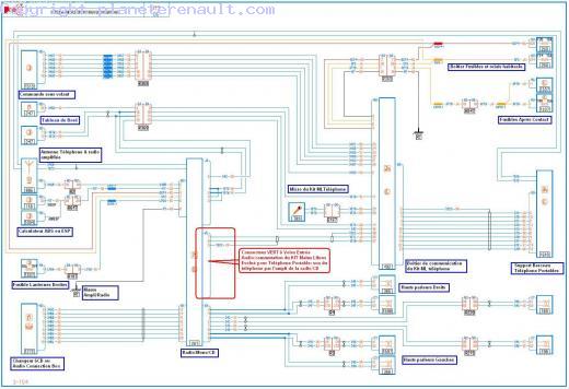
schema-electrique-renault-express-1999-wiring-diagram.pdf
100%

Schema Electrique Renault Express 1999 Wiring Diagram


HTTP://MYDIAGRAM.ONLINE
Revision 3.4 (02/2005)
© 2005 HTTP://MYDIAGRAM.ONLINE. All Rights Reserved.

TABLE OF CONTENTS

Cover1
Table of Contents2
Introduction & Scope3
Safety and Handling4
Symbols & Abbreviations5
Wire Colors & Gauges6
Power Distribution Overview7
Grounding Strategy8
Connector Index & Pinout9
Sensor Inputs10
Actuator Outputs11
Control Unit / Module12
Communication Bus13
Protection: Fuse & Relay14
Test Points & References15
Measurement Procedures16
Troubleshooting Guide17
Common Fault Patterns18
Maintenance & Best Practices19
Appendix & References20
Deep Dive #1 - Signal Integrity & EMC21
Deep Dive #2 - Signal Integrity & EMC22
Deep Dive #3 - Signal Integrity & EMC23
Deep Dive #4 - Signal Integrity & EMC24
Deep Dive #5 - Signal Integrity & EMC25
Deep Dive #6 - Signal Integrity & EMC26
Harness Layout Variant #127
Harness Layout Variant #228
Harness Layout Variant #329
Harness Layout Variant #430
Diagnostic Flowchart #131
Diagnostic Flowchart #232
Diagnostic Flowchart #333
Diagnostic Flowchart #434
Case Study #1 - Real-World Failure35
Case Study #2 - Real-World Failure36
Case Study #3 - Real-World Failure37
Case Study #4 - Real-World Failure38
Case Study #5 - Real-World Failure39
Case Study #6 - Real-World Failure40
Hands-On Lab #1 - Measurement Practice41
Hands-On Lab #2 - Measurement Practice42
Hands-On Lab #3 - Measurement Practice43
Hands-On Lab #4 - Measurement Practice44
Hands-On Lab #5 - Measurement Practice45
Hands-On Lab #6 - Measurement Practice46
Checklist & Form #1 - Quality Verification47
Checklist & Form #2 - Quality Verification48
Checklist & Form #3 - Quality Verification49
Checklist & Form #4 - Quality Verification50
Introduction & Scope Page 3

Preventive maintenance is the core principle behind every reliable electrical system. While wiring diagrams illustrate design intent, maintenance ensures the system remains functional under stressdespite harsh environments, aging, and contamination. A well-preserved wiring network not only prevents costly downtime but also extends component lifespan.

In many cases, wiring breakdowns dont happen instantly. They begin as early-stage defects: a loose connector pin or aging insulation. Without early detection, these tiny imperfections evolve into major faults. Preventive maintenance connects design and durability by intercepting failures at their origin.

A proper maintenance program starts with routine checks. Every wiring systemwhether used in cars, factories, or buildingsshould be visually examined at defined intervals. Look for loose fasteners, heat marks, and oxidation. Areas prone to movement or environmental stress require more frequent checks. Use inspection aids and lighting tools to view hidden harness sections, and document every finding in maintenance logs for traceability.

Cleaning and protection are just as important as inspection. Oil, dirt, and humidity accelerate oxidation and heat generation at contact points. Clean connectors using non-residue solutions and apply protective lubricant sparingly on weather-exposed joints. Avoid solvents that harm plastic housings that damage seals. For outdoor systems, add extra layers of environmental defense to prevent moisture ingress.

Mechanical integrity defines long-term performance. Wires that hang loosely will fail from fatigue. Support harnesses with rubber-lined brackets or clips, typically every 812 inches, and include flex joints where motion occurs. Replace worn grommets immediately to prevent chafing on metal edges. Secure all ground straps tightly and cleanly, using serrated washers for low-resistance bonding.

Electrical verification is another pillar of preventive maintenance. Measure potential difference across major supply and return lines while circuits operate under load. Any reading above normal limits indicates hidden corrosion. Check continuity on standby circuits to confirm they remain intact. Use non-contact temperature sensors to reveal hotspots or weak joints invisible to the eye.

Documentation keeps maintenance organized and traceable. Every modification, splice, or reroute must be recorded on the wiring diagram. Label wires with durable printed IDs and note replacement references. In professional environments, revision logs ensure everyone references the same updated diagram. Technicians who document consistently build a knowledge base that accelerates future repairs.

Training and discipline form another key layer of preventive maintenance. Even experienced electricians make errors when working under pressure. Regular skill calibration workshops on crimping, torque, and inspection procedures keep teams consistent. Always verify tool calibrationan inaccurate meter or torque wrench can compromise repair quality.

In critical sectors such as aerospace, energy, and manufacturing, smart monitoring systems now complement manual inspections. Sensors collect continuous electrical health data, alerting technicians ahead of actual failure. This data-driven approach transforms maintenance from corrective to predictive, allowing problems to be neutralized early.

Preventive maintenance isnt just about fixing breakdowns; its about preserving reliability. A wiring harness that remains secure, organized, and well-labeled behaves stably and safely. Equipment uptime improves, and system dependability is never compromised. The time and care invested repay themselves many times over in longevity and peace of mind.

Within the context of this manual, preventive maintenance serves as the link between theory and reality. Understanding circuits is one skill; preserving them in harsh conditions is another. By adopting structured maintenance programs, technicians transform schematic ideals into lasting reliabilityensuring every joint, wire, and terminal performs exactly as intended.

Figure 1
Safety and Handling Page 4

Working safely requires both awareness and preparation. Before beginning, isolate all energy sources and verify de-energization using the “test-before-touch” rule. Have PPE ready — shield, gloves, and flame-rated clothing are part of standard practice. Avoid distractions and never rush an electrical procedure.

Good handling is really just respect for the parts you’re working with. Never twist two conductors together as a quick fix — use certified connectors or crimp joints. Keep bend radius gentle and support harnesses with cushioned clamps. Avoid routing near heat exchangers, fuel lines, or hydraulic hoses. These mechanical details prevent tomorrow’s electrical failures.

When done, recheck torque on terminals and verify you’re using proper fuse values. Bring power back slowly and watch for abnormal current, noise, or burning smell. Document everything you changed so it can be traced later. Real safety is prevention plus documentation and final verification.

Figure 2
Symbols & Abbreviations Page 5

Schematics use drawn symbols to represent hardware and compact abbreviations to stand in for long component descriptions. A battery icon on the page doesn’t look like the real battery, but it tells you “this node is positive supply.” A zig‑zag or rectangle stands for a resistor; a diode is drawn as an arrow hitting a bar; and a relay is shown as a coil plus contacts.

Abbreviations carry most of the meaning once you start tracing wires. Common tags include REF, TPS, RPM, “5V REG,” and LIN; each tag shows what that line actually does. Most service docs assign connector IDs like C101 / C205 so you can physically locate that plug in the loom.

Because makers invent their own shorthand, you cannot assume two systems agree. A tag like REF might mean voltage reference in one drawing, but “chassis reference” in another, which matters if “Schema Electrique Renault Express 1999 Wiring Diagram” is being diagnosed in Wiring Diagram. To avoid blowing a controller in 2025, decode the legend first and log which pin you touched in the work record at http://mydiagram.online and https://http://mydiagram.online/schema-electrique-renault-express-1999-wiring-diagram/.

Figure 3
Wire Colors & Gauges Page 6

Proper wire color coding and gauge choice form the foundation of safe and efficient electrical design.
Color conveys purpose, while gauge defines how current moves safely across the wiring network.
Red wires usually represent power or positive voltage, black or brown indicate ground, yellow connects to ignition or switching circuits, and blue handles control or data signals.
By following these established color standards, technicians working on “Schema Electrique Renault Express 1999 Wiring Diagram” can immediately identify circuits and prevent wiring mistakes.
Uniform color coding increases safety, simplifies maintenance, and accelerates testing procedures.

The gauge size—AWG or mm²—indicates the wire’s ability to handle current flow safely and efficiently.
Low AWG equals thicker wires for heavy-duty circuits; high AWG means thinner wires suited for low-current signals.
Selecting the correct gauge prevents voltage drops, ensures mechanical durability, and optimizes overall performance.
Within Wiring Diagram, professionals use ISO 6722, SAE J1128, and IEC 60228 to standardize wire sizing and insulation ratings.
These references help maintain uniformity and reliability across all projects involving “Schema Electrique Renault Express 1999 Wiring Diagram”.
Using the wrong wire size can cause resistance issues, heat rise, or failure in the long term.

Good electrical work concludes with precise and detailed documentation.
All wiring data—color, gauge, and path—should be recorded and confirmed for accuracy.
When substitutions or reroutes occur, technicians should clearly label and update these changes in both the schematic and maintenance log.
Inspection photos, voltage reports, and schematics must be archived at http://mydiagram.online for future verification.
Adding timestamps (2025) and audit links (https://http://mydiagram.online/schema-electrique-renault-express-1999-wiring-diagram/) strengthens accountability and simplifies review processes.
By following proper documentation and standards, “Schema Electrique Renault Express 1999 Wiring Diagram” remains safe, efficient, and fully compliant for years.

Figure 4
Power Distribution Overview Page 7

It guarantees controlled transmission of electrical energy from the supply to every branch circuit.
This network balances current levels and shields sensitive components, keeping “Schema Electrique Renault Express 1999 Wiring Diagram” efficient.
Without effective distribution, systems can face voltage fluctuations, overloads, or even component failure.
A reliable power design prevents such risks while ensuring consistent performance and safety in all working conditions.
Ultimately, power distribution transforms complex energy flow into a structured, dependable electrical network.

Developing an efficient power distribution network begins with understanding load capacity and circuit behavior.
All wires, relays, and connectors should be rated by voltage, current, and external conditions.
Engineers in Wiring Diagram typically follow ISO 16750, IEC 61000, and SAE J1113 to maintain consistency and compliance across projects.
Power cables must be isolated from communication lines to avoid electromagnetic noise.
Fuse panels, grounding points, and connectors should be clearly labeled and placed for easy maintenance.
Following these principles allows “Schema Electrique Renault Express 1999 Wiring Diagram” to maintain stable, safe, and efficient energy flow.

Post-installation testing confirms that the system meets design and safety requirements.
Maintenance staff should measure voltage, test continuity, and confirm effective grounding.
All wiring changes should be updated in schematics and stored in the maintenance database.
Upload test results, inspection logs, and notes to http://mydiagram.online for long-term safekeeping.
Attach 2025 and https://http://mydiagram.online/schema-electrique-renault-express-1999-wiring-diagram/ to keep maintenance records accurate and transparent.
Comprehensive testing and records keep “Schema Electrique Renault Express 1999 Wiring Diagram” safe, compliant, and simple to service.

Figure 5
Grounding Strategy Page 8

It offers an electrical baseline that maintains safety, stability, and optimal system function.
It channels excess current into the ground, reducing the risk of electrical shock or failure.
Without proper grounding, “Schema Electrique Renault Express 1999 Wiring Diagram” may face unstable voltage, noise interference, or electrical malfunction.
Proper grounding keeps resistance low and ensures uniform voltage potential throughout the system.
Ultimately, grounding ensures that electrical networks in Wiring Diagram remain safe, stable, and dependable.

A strong grounding plan starts by analyzing soil composition, resistivity, and fault current behavior.
Grounding connections should be secure, rust-proof, and placed for easy maintenance access.
In Wiring Diagram, international standards like IEC 60364 and IEEE 142 are followed to ensure safe and efficient system grounding.
The conductors used should be large enough to handle expected fault currents while maintaining minimal resistance.
A unified grounding system eliminates differences in potential and ensures equal voltage distribution.
Through proper grounding, “Schema Electrique Renault Express 1999 Wiring Diagram” maintains steady operation and improved component longevity.

To maintain system reliability, regular inspection and testing are essential.
Engineers need to assess grounding resistance, bond quality, and circuit connection health.
Detected damage or corrosion must be fixed promptly to restore safety and performance.
All reports and measurements should be documented to maintain compliance and traceability.
Routine testing every 6–12 months ensures the grounding system continues to perform at its best.
By maintaining inspection schedules, “Schema Electrique Renault Express 1999 Wiring Diagram” ensures stable, safe, and efficient operation for years.

Figure 6
Connector Index & Pinout Page 9

Schema Electrique Renault Express 1999 Wiring Diagram Full Manual – Connector Index & Pinout 2025

Regular inspection of connectors helps sustain performance and avoids intermittent faults. {Dust, moisture, and vibration are common causes of poor connectivity and short circuits.|Environmental exposure—such as heat and humidity—can degrade connector pins over time.|Loose fittings or o...

Always inspect connector pins and housings visually before assembly to prevent poor contact. {Applying dielectric grease to terminal joints provides additional protection in high-humidity conditions.|Protective compounds help seal terminals from oxygen and water exposure.|Use non-conductive grease to prevent rust...

Only use properly sized adapter pins when checking voltage or continuity on connectors. {Following these maintenance habits helps reduce downtime and keeps the wiring harness in optimal condition.|Preventive connector care ensures consistent current flow and fewer electrical failures.|A disciplined inspection routine exten...

Figure 7
Sensor Inputs Page 10

Schema Electrique Renault Express 1999 Wiring Diagram Wiring Guide – Sensor Inputs Reference 2025

Manifold Absolute Pressure (MAP) sensors are used to measure air pressure inside the intake manifold. Pressure changes within the manifold are converted into electrical signals the ECU can interpret.

Most MAP sensors use piezoresistive elements that change resistance under pressure variations. MAP sensors typically output a reference voltage of 5V and a variable signal between 0.5V and 4.5V depending on vacuum level.

Incorrect pressure readings disrupt mixture control and trigger fault codes. Technicians should inspect hoses and connectors for leaks before replacing the sensor.

Figure 8
Actuator Outputs Page 11

Schema Electrique Renault Express 1999 Wiring Diagram – Actuator Outputs 2025

It ensures the correct balance between performance, emissions, and fuel economy. {Modern vehicles use electronically controlled turbo actuators instead of traditional vacuum types.|The ECU sends precise signals to position sensors and motors within the actuator assembly.|This allows continuous boost ad...

Pulse-width modulation (PWM) signals define actuator movement and response time. Vacuum-controlled actuators rely on solenoid valves to regulate diaphragm movement.

Common problems include sticking vanes, failed motors, or position sensor errors. Proper calibration prevents engine stress and turbocharger damage.

Figure 9
Control Unit / Module Page 12

Schema Electrique Renault Express 1999 Wiring Diagram Full Manual – Actuator Outputs 2025

A relay allows a small control current to switch a larger load safely and efficiently. {When energized, the relay coil generates a magnetic field that pulls a contact arm, closing or opening the circuit.|This mechanism isolates the control side from the load side, protecting sensitive electronics.|The coil’s inductive ...

Electromechanical relays use moving contacts, while solid-state designs rely on semiconductor switching. {Automotive and industrial systems use relays for lamps, fans, motors, and heating elements.|Their ability to handle heavy loads makes them essential in both safety and automation applications.|Each relay type has unique advantages depending o...

A clicking sound usually indicates mechanical operation but not necessarily good contact condition. {Proper relay diagnostics ensure circuit reliability and prevent overload damage.|Regular relay inspection extends service life and maintains stable actuator response.|Understanding relay behavior helps impro...

Figure 10
Communication Bus Page 13

As the distributed nervous system of the
vehicle, the communication bus eliminates bulky point-to-point wiring by
delivering unified message pathways that significantly reduce harness
mass and electrical noise. By enforcing timing discipline and
arbitration rules, the system ensures each module receives critical
updates without interruption.

Modern platforms rely on a hierarchy of standards including CAN for
deterministic control, LIN for auxiliary functions, FlexRay for
high-stability timing loops, and Ethernet for high-bandwidth sensing.
Each protocol fulfills unique performance roles that enable safe
coordination of braking, torque management, climate control, and
driver-assistance features.

Communication failures may arise from impedance drift, connector
oxidation, EMI bursts, or degraded shielding, often manifesting as
intermittent sensor dropouts, delayed actuator behavior, or corrupted
frames. Diagnostics require voltage verification, termination checks,
and waveform analysis to isolate the failing segment.

Figure 11
Protection: Fuse & Relay Page 14

Protection systems in Schema Electrique Renault Express 1999 Wiring Diagram 2025 Wiring Diagram rely on fuses and relays
to form a controlled barrier between electrical loads and the vehicle’s
power distribution backbone. These elements react instantly to abnormal
current patterns, stopping excessive amperage before it cascades into
critical modules. By segmenting circuits into isolated branches, the
system protects sensors, control units, lighting, and auxiliary
equipment from thermal stress and wiring burnout.

In modern architectures, relays handle repetitive activation
cycles, executing commands triggered by sensors or control software.
Their isolation capabilities reduce stress on low‑current circuits,
while fuses provide sacrificial protection whenever load spikes exceed
tolerance thresholds. Together they create a multi‑layer defense grid
adaptable to varying thermal and voltage demands.

Common failures within fuse‑relay assemblies often trace back to
vibration fatigue, corroded terminals, oxidized blades, weak coil
windings, or overheating caused by loose socket contacts. Drivers may
observe symptoms such as flickering accessories, intermittent actuator
response, disabled subsystems, or repeated fuse blows. Proper
diagnostics require voltage‑drop measurements, socket stability checks,
thermal inspection, and coil resistance evaluation.

Figure 12
Test Points & References Page 15

Within modern automotive systems, reference
pads act as structured anchor locations for stabilized-supply
evaluation, enabling repeatable and consistent measurement sessions.
Their placement across sensor returns, control-module feeds, and
distribution junctions ensures that technicians can evaluate baseline
conditions without interference from adjacent circuits. This allows
diagnostic tools to interpret subsystem health with greater accuracy.

Technicians rely on these access nodes to conduct dynamic-load event
testing, waveform pattern checks, and signal-shape verification across
multiple operational domains. By comparing known reference values
against observed readings, inconsistencies can quickly reveal poor
grounding, voltage imbalance, or early-stage conductor fatigue. These
cross-checks are essential when diagnosing sporadic faults that only
appear during thermal expansion cycles or variable-load driving
conditions.

Common issues identified through test point evaluation include voltage
fluctuation, unstable ground return, communication dropouts, and erratic
sensor baselines. These symptoms often arise from corrosion, damaged
conductors, poorly crimped terminals, or EMI contamination along
high-frequency lines. Proper analysis requires oscilloscope tracing,
continuity testing, and resistance indexing to compare expected values
with real-time data.

Figure 13
Measurement Procedures Page 16

Measurement procedures for Schema Electrique Renault Express 1999 Wiring Diagram 2025 Wiring Diagram begin with
resistance drift inspection to establish accurate diagnostic
foundations. Technicians validate stable reference points such as
regulator outputs, ground planes, and sensor baselines before proceeding
with deeper analysis. This ensures reliable interpretation of electrical
behavior under different load and temperature conditions.

Technicians utilize these measurements to evaluate waveform stability,
resistance drift inspection, and voltage behavior across multiple
subsystem domains. Comparing measured values against specifications
helps identify root causes such as component drift, grounding
inconsistencies, or load-induced fluctuations.

Frequent
anomalies identified during procedure-based diagnostics include ground
instability, periodic voltage collapse, digital noise interference, and
contact resistance spikes. Consistent documentation and repeated
sampling are essential to ensure accurate diagnostic conclusions.

Figure 14
Troubleshooting Guide Page 17

Troubleshooting for Schema Electrique Renault Express 1999 Wiring Diagram 2025 Wiring Diagram begins with generalized
subsystem checks, ensuring the diagnostic process starts with clarity
and consistency. By checking basic system readiness, technicians avoid
deeper misinterpretations.

Technicians use scan-tool parameter correlation to narrow fault
origins. By validating electrical integrity and observing behavior under
controlled load, they identify abnormal deviations early.

Degraded shielding may allow external electromagnetic bursts to distort
communication lines. Shield continuity checks and rewrapping harness
segments mitigate the issue.

Figure 15
Common Fault Patterns Page 18

Common fault patterns in Schema Electrique Renault Express 1999 Wiring Diagram 2025 Wiring Diagram frequently stem from
CAN bus frame corruption caused by EMI exposure, a condition that
introduces irregular electrical behavior observable across multiple
subsystems. Early-stage symptoms are often subtle, manifesting as small
deviations in baseline readings or intermittent inconsistencies that
disappear as quickly as they appear. Technicians must therefore begin
diagnostics with broad-spectrum inspection, ensuring that fundamental
supply and return conditions are stable before interpreting more complex
indicators.

When examining faults tied to CAN bus frame corruption caused by EMI
exposure, technicians often observe fluctuations that correlate with
engine heat, module activation cycles, or environmental humidity. These
conditions can cause reference rails to drift or sensor outputs to lose
linearity, leading to miscommunication between control units. A
structured diagnostic workflow involves comparing real-time readings to
known-good values, replicating environmental conditions, and isolating
behavior changes under controlled load simulations.

Left unresolved, CAN bus frame corruption caused by EMI exposure
may cause cascading failures as modules attempt to compensate for
distorted data streams. This can trigger false DTCs, unpredictable load
behavior, delayed actuator response, and even safety-feature
interruptions. Comprehensive analysis requires reviewing subsystem
interaction maps, recreating stress conditions, and validating each
reference point’s consistency under both static and dynamic operating
states.

Figure 16
Maintenance & Best Practices Page 19

Maintenance and best practices for Schema Electrique Renault Express 1999 Wiring Diagram 2025 Wiring Diagram place
strong emphasis on long-term wiring lifecycle preservation, ensuring
that electrical reliability remains consistent across all operating
conditions. Technicians begin by examining the harness environment,
verifying routing paths, and confirming that insulation remains intact.
This foundational approach prevents intermittent issues commonly
triggered by heat, vibration, or environmental contamination.

Technicians
analyzing long-term wiring lifecycle preservation typically monitor
connector alignment, evaluate oxidation levels, and inspect wiring for
subtle deformations caused by prolonged thermal exposure. Protective
dielectric compounds and proper routing practices further contribute to
stable electrical pathways that resist mechanical stress and
environmental impact.

Issues associated with long-term wiring lifecycle preservation
frequently arise from overlooked early wear signs, such as minor contact
resistance increases or softening of insulation under prolonged heat.
Regular maintenance cycles—including resistance indexing, pressure
testing, and moisture-barrier reinforcement—ensure that electrical
pathways remain dependable and free from hidden vulnerabilities.

Figure 17
Appendix & References Page 20

The appendix for Schema Electrique Renault Express 1999 Wiring Diagram 2025 Wiring Diagram serves as a consolidated
reference hub focused on subsystem classification nomenclature, offering
technicians consistent terminology and structured documentation
practices. By collecting technical descriptors, abbreviations, and
classification rules into a single section, the appendix streamlines
interpretation of wiring layouts across diverse platforms. This ensures
that even complex circuit structures remain approachable through
standardized definitions and reference cues.

Documentation related to subsystem classification nomenclature
frequently includes structured tables, indexing lists, and lookup
summaries that reduce the need to cross‑reference multiple sources
during system evaluation. These entries typically describe connector
types, circuit categories, subsystem identifiers, and signal behavior
definitions. By keeping these details accessible, technicians can
accelerate the interpretation of wiring diagrams and troubleshoot with
greater accuracy.

Robust appendix material for subsystem classification
nomenclature strengthens system coherence by standardizing definitions
across numerous technical documents. This reduces ambiguity, supports
proper cataloging of new components, and helps technicians avoid
misinterpretation that could arise from inconsistent reference
structures.

Figure 18
Deep Dive #1 - Signal Integrity & EMC Page 21

Deep analysis of signal integrity in Schema Electrique Renault Express 1999 Wiring Diagram 2025 Wiring Diagram requires
investigating how reflection artifacts caused by unterminated lines
disrupts expected waveform performance across interconnected circuits.
As signals propagate through long harnesses, subtle distortions
accumulate due to impedance shifts, parasitic capacitance, and external
electromagnetic stress. This foundational assessment enables technicians
to understand where integrity loss begins and how it
evolves.

Patterns associated with reflection artifacts caused by
unterminated lines often appear during subsystem switching—ignition
cycles, relay activation, or sudden load redistribution. These events
inject disturbances through shared conductors, altering reference
stability and producing subtle waveform irregularities. Multi‑state
capture sequences are essential for distinguishing true EMC faults from
benign system noise.

If reflection
artifacts caused by unterminated lines persists, cascading instability
may arise: intermittent communication, corrupt data frames, or erratic
control logic. Mitigation requires strengthening shielding layers,
rebalancing grounding networks, refining harness layout, and applying
proper termination strategies. These corrective steps restore signal
coherence under EMC stress.

Figure 19
Deep Dive #2 - Signal Integrity & EMC Page 22

Advanced EMC evaluation in Schema Electrique Renault Express 1999 Wiring Diagram 2025 Wiring Diagram requires close
study of EMC coupling through asymmetrical grounding paths, a phenomenon
that can significantly compromise waveform predictability. As systems
scale toward higher bandwidth and greater sensitivity, minor deviations
in signal symmetry or reference alignment become amplified.
Understanding the initial conditions that trigger these distortions
allows technicians to anticipate system vulnerabilities before they
escalate.

Systems experiencing EMC coupling through
asymmetrical grounding paths frequently show inconsistencies during fast
state transitions such as ignition sequencing, data bus arbitration, or
actuator modulation. These inconsistencies originate from embedded EMC
interactions that vary with harness geometry, grounding quality, and
cable impedance. Multi‑stage capture techniques help isolate the root
interaction layer.

If left unresolved, EMC coupling through asymmetrical
grounding paths may trigger cascading disruptions including frame
corruption, false sensor readings, and irregular module coordination.
Effective countermeasures include controlled grounding, noise‑filter
deployment, re‑termination of critical paths, and restructuring of cable
routing to minimize electromagnetic coupling.

Figure 20
Deep Dive #3 - Signal Integrity & EMC Page 23

A comprehensive
assessment of waveform stability requires understanding the effects of
skin-effect driven signal attenuation at elevated frequencies, a factor
capable of reshaping digital and analog signal profiles in subtle yet
impactful ways. This initial analysis phase helps technicians identify
whether distortions originate from physical harness geometry,
electromagnetic ingress, or internal module reference instability.

When skin-effect driven signal attenuation at elevated frequencies is
active within a vehicle’s electrical environment, technicians may
observe shift in waveform symmetry, rising-edge deformation, or delays
in digital line arbitration. These behaviors require examination under
multiple load states, including ignition operation, actuator cycling,
and high-frequency interference conditions. High-bandwidth oscilloscopes
and calibrated field probes reveal the hidden nature of such
distortions.

If
unchecked, skin-effect driven signal attenuation at elevated frequencies
can escalate into broader electrical instability, causing corruption of
data frames, synchronization loss between modules, and unpredictable
actuator behavior. Effective corrective action requires ground isolation
improvements, controlled harness rerouting, adaptive termination
practices, and installation of noise-suppression elements tailored to
the affected frequency range.

Figure 21
Deep Dive #4 - Signal Integrity & EMC Page 24

Evaluating advanced signal‑integrity interactions involves
examining the influence of conducted spectral noise entering precision
analog channels, a phenomenon capable of inducing significant waveform
displacement. These disruptions often develop gradually, becoming
noticeable only when communication reliability begins to drift or
subsystem timing loses coherence.

When conducted spectral noise entering precision analog channels is
active, waveform distortion may manifest through amplitude instability,
reference drift, unexpected ringing artifacts, or shifting propagation
delays. These effects often correlate with subsystem transitions,
thermal cycles, actuator bursts, or environmental EMI fluctuations.
High‑bandwidth test equipment reveals the microscopic deviations hidden
within normal signal envelopes.

If unresolved, conducted spectral noise entering
precision analog channels may escalate into severe operational
instability, corrupting digital frames or disrupting tight‑timing
control loops. Effective mitigation requires targeted filtering,
optimized termination schemes, strategic rerouting, and harmonic
suppression tailored to the affected frequency bands.

Figure 22
Deep Dive #5 - Signal Integrity & EMC Page 25

Advanced waveform diagnostics in Schema Electrique Renault Express 1999 Wiring Diagram 2025 Wiring Diagram must account
for lossy‑media propagation degrading analog sensor fidelity, a complex
interaction that reshapes both analog and digital signal behavior across
interconnected subsystems. As modern vehicle architectures push higher
data rates and consolidate multiple electrical domains, even small EMI
vectors can distort timing, amplitude, and reference stability.

Systems exposed to lossy‑media propagation degrading analog
sensor fidelity often show instability during rapid subsystem
transitions. This instability results from interference coupling into
sensitive wiring paths, causing skew, jitter, or frame corruption.
Multi-domain waveform capture reveals how these disturbances propagate
and interact.

If left
unresolved, lossy‑media propagation degrading analog sensor fidelity may
evolve into severe operational instability—ranging from data corruption
to sporadic ECU desynchronization. Effective countermeasures include
refining harness geometry, isolating radiated hotspots, enhancing
return-path uniformity, and implementing frequency-specific suppression
techniques.

Figure 23
Deep Dive #6 - Signal Integrity & EMC Page 26

Signal behavior
under the influence of rare intermittent EMI bursts triggered by
environmental charge gradients becomes increasingly unpredictable as
electrical environments evolve toward higher voltage domains, denser
wiring clusters, and more sensitive digital logic. Deep initial
assessment requires waveform sampling under various load conditions to
establish a reliable diagnostic baseline.

When rare intermittent EMI bursts triggered by environmental charge
gradients occurs, technicians may observe inconsistent rise-times,
amplitude drift, complex ringing patterns, or intermittent jitter
artifacts. These symptoms often appear during subsystem
interactions—such as inverter ramps, actuator bursts, ADAS
synchronization cycles, or ground-potential fluctuations. High-bandwidth
oscilloscopes and spectrum analyzers reveal hidden distortion
signatures.

If unresolved, rare
intermittent EMI bursts triggered by environmental charge gradients can
escalate into catastrophic failure modes—ranging from module resets and
actuator misfires to complete subsystem desynchronization. Effective
corrective actions include tuning impedance profiles, isolating radiated
hotspots, applying frequency-specific suppression, and refining
communication topology to ensure long-term stability.

Figure 24
Harness Layout Variant #1 Page 27

In-depth planning of
harness architecture involves understanding how noise‑minimizing cable
spacing rules for high-current circuits affects long-term stability. As
wiring systems grow more complex, engineers must consider structural
constraints, subsystem interaction, and the balance between electrical
separation and mechanical compactness.

During layout development, noise‑minimizing cable spacing rules for
high-current circuits can determine whether circuits maintain clean
signal behavior under dynamic operating conditions. Mechanical and
electrical domains intersect heavily in modern harness designs—routing
angle, bundling tightness, grounding alignment, and mounting intervals
all affect susceptibility to noise, wear, and heat.

Proper control of noise‑minimizing cable spacing rules for high-current
circuits ensures reliable operation, simplified manufacturing, and
long-term durability. Technicians and engineers apply routing
guidelines, shielding rules, and structural anchoring principles to
ensure consistent performance regardless of environment or subsystem
load.

Figure 25
Harness Layout Variant #2 Page 28

Harness Layout Variant #2 for Schema Electrique Renault Express 1999 Wiring Diagram 2025 Wiring Diagram focuses on
floating ground-strap routing stabilizing reference potentials, a
structural and electrical consideration that influences both reliability
and long-term stability. As modern vehicles integrate more electronic
modules, routing strategies must balance physical constraints with the
need for predictable signal behavior.

During refinement, floating ground-strap routing stabilizing reference
potentials impacts EMI susceptibility, heat distribution, vibration
loading, and ground continuity. Designers analyze spacing, elevation
changes, shielding alignment, tie-point positioning, and path curvature
to ensure the harness resists mechanical fatigue while maintaining
electrical integrity.

Managing floating ground-strap routing stabilizing reference potentials
effectively results in improved robustness, simplified maintenance, and
enhanced overall system stability. Engineers apply isolation rules,
structural reinforcement, and optimized routing logic to produce a
layout capable of sustaining long-term operational loads.

Figure 26
Harness Layout Variant #3 Page 29

Engineering Harness Layout
Variant #3 involves assessing how enhanced shielding alignment for
proximity to infotainment modules influences subsystem spacing, EMI
exposure, mounting geometry, and overall routing efficiency. As harness
density increases, thoughtful initial planning becomes critical to
prevent premature system fatigue.

During refinement, enhanced shielding alignment for proximity to
infotainment modules can impact vibration resistance, shielding
effectiveness, ground continuity, and stress distribution along key
segments. Designers analyze bundle thickness, elevation shifts,
structural transitions, and separation from high‑interference components
to optimize both mechanical and electrical performance.

Managing enhanced shielding alignment for proximity to infotainment
modules effectively ensures robust, serviceable, and EMI‑resistant
harness layouts. Engineers rely on optimized routing classifications,
grounding structures, anti‑wear layers, and anchoring intervals to
produce a layout that withstands long-term operational loads.

Figure 27
Harness Layout Variant #4 Page 30

Harness Layout Variant #4 for Schema Electrique Renault Express 1999 Wiring Diagram 2025 Wiring Diagram emphasizes crash-safe routing redundancies across
deformation zones, combining mechanical and electrical considerations to maintain cable stability across
multiple vehicle zones. Early planning defines routing elevation, clearance from heat sources, and anchoring
points so each branch can absorb vibration and thermal expansion without overstressing connectors.

In
real-world operation, crash-safe routing redundancies across deformation zones affects signal quality near
actuators, motors, and infotainment modules. Cable elevation, branch sequencing, and anti-chafe barriers
reduce premature wear. A combination of elastic tie-points, protective sleeves, and low-profile clips keeps
bundles orderly yet flexible under dynamic loads.

Proper control of crash-safe routing redundancies across
deformation zones minimizes moisture intrusion, terminal corrosion, and cross-path noise. Best practices
include labeled manufacturing references, measured service loops, and HV/LV clearance audits. When components
are updated, route documentation and measurement points simplify verification without dismantling the entire
assembly.

Figure 28
Diagnostic Flowchart #1 Page 31

Diagnostic Flowchart #1 for Schema Electrique Renault Express 1999 Wiring Diagram 2025 Wiring Diagram begins with step‑by‑step actuator response mapping under
diagnostic mode, establishing a precise entry point that helps technicians determine whether symptoms
originate from signal distortion, grounding faults, or early‑stage communication instability. A consistent
diagnostic baseline prevents unnecessary part replacement and improves accuracy. As diagnostics progress, step‑by‑step actuator response mapping under diagnostic mode becomes a
critical branch factor influencing decisions relating to grounding integrity, power sequencing, and network
communication paths. This structured logic ensures accuracy even when symptoms appear scattered. If step‑by‑step actuator response mapping under diagnostic mode is
not thoroughly validated, subtle faults can cascade into widespread subsystem instability. Reinforcing each
decision node with targeted measurements improves long‑term reliability and prevents misdiagnosis.

Figure 29
Diagnostic Flowchart #2 Page 32

The initial phase of Diagnostic Flowchart #2
emphasizes multi-branch continuity validation for distributed harnesses, ensuring that technicians validate
foundational electrical relationships before evaluating deeper subsystem interactions. This prevents
diagnostic drift and reduces unnecessary component replacements. As the diagnostic flow advances, multi-
branch continuity validation for distributed harnesses shapes the logic of each decision node. Mid‑stage
evaluation involves segmenting power, ground, communication, and actuation pathways to progressively narrow
down fault origins. This stepwise refinement is crucial for revealing timing‑related and load‑sensitive
anomalies. If multi-branch continuity validation for distributed harnesses is not thoroughly examined,
intermittent signal distortion or cascading electrical faults may remain hidden. Reinforcing each decision
node with precise measurement steps prevents misdiagnosis and strengthens long-term reliability.

Figure 30
Diagnostic Flowchart #3 Page 33

The first branch of Diagnostic Flowchart #3 prioritizes PWM‑related actuator inconsistencies
under load, ensuring foundational stability is confirmed before deeper subsystem exploration. This prevents
misdirection caused by intermittent or misleading electrical behavior. As the flowchart progresses,
PWM‑related actuator inconsistencies under load defines how mid‑stage decisions are segmented. Technicians
sequentially eliminate power, ground, communication, and actuation domains while interpreting timing shifts,
signal drift, or misalignment across related circuits. Once PWM‑related actuator inconsistencies under load is fully evaluated across multiple load
states, the technician can confirm or dismiss entire fault categories. This structured approach enhances
long‑term reliability and reduces repeat troubleshooting visits.

Figure 31
Diagnostic Flowchart #4 Page 34

Diagnostic Flowchart #4 for Schema Electrique Renault Express 1999 Wiring Diagram 2025
Wiring Diagram focuses on hybrid HV/LV interference tracking using flow branches, laying the foundation for a
structured fault‑isolation path that eliminates guesswork and reduces unnecessary component swapping. The
first stage examines core references, voltage stability, and baseline communication health to determine
whether the issue originates in the primary network layer or in a secondary subsystem. Technicians follow a
branched decision flow that evaluates signal symmetry, grounding patterns, and frame stability before
advancing into deeper diagnostic layers. As the evaluation continues, hybrid HV/LV interference tracking
using flow branches becomes the controlling factor for mid‑level branch decisions. This includes correlating
waveform alignment, identifying momentary desync signatures, and interpreting module wake‑timing conflicts. By
dividing the diagnostic pathway into focused electrical domains—power delivery, grounding integrity,
communication architecture, and actuator response—the flowchart ensures that each stage removes entire
categories of faults with minimal overlap. This structured segmentation accelerates troubleshooting and
increases diagnostic precision. The final stage ensures that hybrid HV/LV interference tracking using flow branches is validated
under multiple operating conditions, including thermal stress, load spikes, vibration, and state transitions.
These controlled stress points help reveal hidden instabilities that may not appear during static testing.
Completing all verification nodes ensures long‑term stability, reducing the likelihood of recurring issues and
enabling technicians to document clear, repeatable steps for future diagnostics.

Figure 32
Case Study #1 - Real-World Failure Page 35

Case Study #1 for Schema Electrique Renault Express 1999 Wiring Diagram 2025 Wiring Diagram examines a real‑world failure involving ECU timing instability
triggered by corrupted firmware blocks. The issue first appeared as an intermittent symptom that did not
trigger a consistent fault code, causing technicians to suspect unrelated components. Early observations
highlighted irregular electrical behavior, such as momentary signal distortion, delayed module responses, or
fluctuating reference values. These symptoms tended to surface under specific thermal, vibration, or load
conditions, making replication difficult during static diagnostic tests. Further investigation into ECU
timing instability triggered by corrupted firmware blocks required systematic measurement across power
distribution paths, grounding nodes, and communication channels. Technicians used targeted diagnostic
flowcharts to isolate variables such as voltage drop, EMI exposure, timing skew, and subsystem
desynchronization. By reproducing the fault under controlled conditions—applying heat, inducing vibration, or
simulating high load—they identified the precise moment the failure manifested. This structured process
eliminated multiple potential contributors, narrowing the fault domain to a specific harness segment,
component group, or module logic pathway. The confirmed cause tied to ECU timing instability triggered by
corrupted firmware blocks allowed technicians to implement the correct repair, whether through component
replacement, harness restoration, recalibration, or module reprogramming. After corrective action, the system
was subjected to repeated verification cycles to ensure long‑term stability under all operating conditions.
Documenting the failure pattern and diagnostic sequence provided valuable reference material for similar
future cases, reducing diagnostic time and preventing unnecessary part replacement.

Figure 33
Case Study #2 - Real-World Failure Page 36

Case Study #2 for Schema Electrique Renault Express 1999 Wiring Diagram 2025 Wiring Diagram examines a real‑world failure involving sensor contamination
leading to non‑linear analog output distortion. The issue presented itself with intermittent symptoms that
varied depending on temperature, load, or vehicle motion. Technicians initially observed irregular system
responses, inconsistent sensor readings, or sporadic communication drops. Because the symptoms did not follow
a predictable pattern, early attempts at replication were unsuccessful, leading to misleading assumptions
about unrelated subsystems. A detailed investigation into sensor contamination leading to non‑linear analog
output distortion required structured diagnostic branching that isolated power delivery, ground stability,
communication timing, and sensor integrity. Using controlled diagnostic tools, technicians applied thermal
load, vibration, and staged electrical demand to recreate the failure in a measurable environment. Progressive
elimination of subsystem groups—ECUs, harness segments, reference points, and actuator pathways—helped reveal
how the failure manifested only under specific operating thresholds. This systematic breakdown prevented
misdiagnosis and reduced unnecessary component swaps. Once the cause linked to sensor contamination leading
to non‑linear analog output distortion was confirmed, the corrective action involved either reconditioning the
harness, replacing the affected component, reprogramming module firmware, or adjusting calibration parameters.
Post‑repair validation cycles were performed under varied conditions to ensure long‑term reliability and
prevent future recurrence. Documentation of the failure characteristics, diagnostic sequence, and final
resolution now serves as a reference for addressing similar complex faults more efficiently.

Figure 34
Case Study #3 - Real-World Failure Page 37

Case Study #3 for Schema Electrique Renault Express 1999 Wiring Diagram 2025 Wiring Diagram focuses on a real‑world failure involving frame‑retry escalation on
Ethernet‑based modules under RF interference. Technicians first observed erratic system behavior, including
fluctuating sensor values, delayed control responses, and sporadic communication warnings. These symptoms
appeared inconsistently, often only under specific temperature, load, or vibration conditions. Early
troubleshooting attempts failed to replicate the issue reliably, creating the impression of multiple unrelated
subsystem faults rather than a single root cause. To investigate frame‑retry escalation on Ethernet‑based
modules under RF interference, a structured diagnostic approach was essential. Technicians conducted staged
power and ground validation, followed by controlled stress testing that included thermal loading, vibration
simulation, and alternating electrical demand. This method helped reveal the precise operational threshold at
which the failure manifested. By isolating system domains—communication networks, power rails, grounding
nodes, and actuator pathways—the diagnostic team progressively eliminated misleading symptoms and narrowed the
problem to a specific failure mechanism. After identifying the underlying cause tied to frame‑retry
escalation on Ethernet‑based modules under RF interference, technicians carried out targeted corrective
actions such as replacing compromised components, restoring harness integrity, updating ECU firmware, or
recalibrating affected subsystems. Post‑repair validation cycles confirmed stable performance across all
operating conditions. The documented diagnostic path and resolution now serve as a repeatable reference for
addressing similar failures with greater speed and accuracy.

Figure 35
Case Study #4 - Real-World Failure Page 38

Case Study #4 for Schema Electrique Renault Express 1999 Wiring Diagram 2025 Wiring Diagram examines a high‑complexity real‑world failure involving relay coil
desaturation during rapid thermal cycling causing unpredictable switching. The issue manifested across
multiple subsystems simultaneously, creating an array of misleading symptoms ranging from inconsistent module
responses to distorted sensor feedback and intermittent communication warnings. Initial diagnostics were
inconclusive due to the fault’s dependency on vibration, thermal shifts, or rapid load changes. These
fluctuating conditions allowed the failure to remain dormant during static testing, pushing technicians to
explore deeper system interactions that extended beyond conventional troubleshooting frameworks. To
investigate relay coil desaturation during rapid thermal cycling causing unpredictable switching, technicians
implemented a layered diagnostic workflow combining power‑rail monitoring, ground‑path validation, EMI
tracing, and logic‑layer analysis. Stress tests were applied in controlled sequences to recreate the precise
environment in which the instability surfaced—often requiring synchronized heat, vibration, and electrical
load modulation. By isolating communication domains, verifying timing thresholds, and comparing analog sensor
behavior under dynamic conditions, the diagnostic team uncovered subtle inconsistencies that pointed toward
deeper system‑level interactions rather than isolated component faults. After confirming the root mechanism
tied to relay coil desaturation during rapid thermal cycling causing unpredictable switching, corrective
action involved component replacement, harness reconditioning, ground‑plane reinforcement, or ECU firmware
restructuring depending on the failure’s nature. Technicians performed post‑repair endurance tests that
included repeated thermal cycling, vibration exposure, and electrical stress to guarantee long‑term system
stability. Thorough documentation of the analysis method, failure pattern, and final resolution now serves as
a highly valuable reference for identifying and mitigating similar high‑complexity failures in the future.

Figure 36
Case Study #5 - Real-World Failure Page 39

Case Study #5 for Schema Electrique Renault Express 1999 Wiring Diagram 2025 Wiring Diagram investigates a complex real‑world failure involving memory‑bank
fragmentation disrupting ECU boot synchronization. The issue initially presented as an inconsistent mixture of
delayed system reactions, irregular sensor values, and sporadic communication disruptions. These events tended
to appear under dynamic operational conditions—such as elevated temperatures, sudden load transitions, or
mechanical vibration—which made early replication attempts unreliable. Technicians encountered symptoms
occurring across multiple modules simultaneously, suggesting a deeper systemic interaction rather than a
single isolated component failure. During the investigation of memory‑bank fragmentation disrupting ECU boot
synchronization, a multi‑layered diagnostic workflow was deployed. Technicians performed sequential power‑rail
mapping, ground‑plane verification, and high‑frequency noise tracing to detect hidden instabilities.
Controlled stress testing—including targeted heat application, induced vibration, and variable load
modulation—was carried out to reproduce the failure consistently. The team methodically isolated subsystem
domains such as communication networks, analog sensor paths, actuator control logic, and module
synchronization timing. This progressive elimination approach identified critical operational thresholds where
the failure reliably emerged. After determining the underlying mechanism tied to memory‑bank fragmentation
disrupting ECU boot synchronization, technicians carried out corrective actions that ranged from harness
reconditioning and connector reinforcement to firmware restructuring and recalibration of affected modules.
Post‑repair validation involved repeated cycles of vibration, thermal stress, and voltage fluctuation to
ensure long‑term stability and eliminate the possibility of recurrence. The documented resolution pathway now
serves as an advanced reference model for diagnosing similarly complex failures across modern vehicle
platforms.

Figure 37
Case Study #6 - Real-World Failure Page 40

Case Study #6 for Schema Electrique Renault Express 1999 Wiring Diagram 2025 Wiring Diagram examines a complex real‑world failure involving HV/LV interference
coupling amplifying analog‑signal noise. Symptoms emerged irregularly, with clustered faults appearing across
unrelated modules, giving the impression of multiple simultaneous subsystem failures. These irregularities
depended strongly on vibration, temperature shifts, or abrupt electrical load changes, making the issue
difficult to reproduce during initial diagnostic attempts. Technicians noted inconsistent sensor feedback,
communication delays, and momentary power‑rail fluctuations that persisted without generating definitive fault
codes. The investigation into HV/LV interference coupling amplifying analog‑signal noise required a
multi‑layer diagnostic strategy combining signal‑path tracing, ground stability assessment, and high‑frequency
noise evaluation. Technicians executed controlled stress tests—including thermal cycling, vibration induction,
and staged electrical loading—to reveal the exact thresholds at which the fault manifested. Using structured
elimination across harness segments, module clusters, and reference nodes, they isolated subtle timing
deviations, analog distortions, or communication desynchronization that pointed toward a deeper systemic
failure mechanism rather than isolated component malfunction. Once HV/LV interference coupling amplifying
analog‑signal noise was identified as the root failure mechanism, targeted corrective measures were
implemented. These included harness reinforcement, connector replacement, firmware restructuring,
recalibration of key modules, or ground‑path reconfiguration depending on the nature of the instability.
Post‑repair endurance runs with repeated vibration, heat cycles, and voltage stress ensured long‑term
reliability. Documentation of the diagnostic sequence and recovery pathway now provides a vital reference for
detecting and resolving similarly complex failures more efficiently in future service operations.

Figure 38
Hands-On Lab #1 - Measurement Practice Page 41

Hands‑On Lab #1 for Schema Electrique Renault Express 1999 Wiring Diagram 2025 Wiring Diagram focuses on ABS sensor signal integrity analysis during wheel
rotation. This exercise teaches technicians how to perform structured diagnostic measurements using
multimeters, oscilloscopes, current probes, and differential tools. The initial phase emphasizes establishing
a stable baseline by checking reference voltages, verifying continuity, and confirming ground integrity. These
foundational steps ensure that subsequent measurements reflect true system behavior rather than secondary
anomalies introduced by poor probing technique or unstable electrical conditions. During the measurement
routine for ABS sensor signal integrity analysis during wheel rotation, technicians analyze dynamic behavior
by applying controlled load, capturing waveform transitions, and monitoring subsystem responses. This includes
observing timing shifts, duty‑cycle changes, ripple patterns, or communication irregularities. By replicating
real operating conditions—thermal changes, vibration, or electrical demand spikes—technicians gain insight
into how the system behaves under stress. This approach allows deeper interpretation of patterns that static
readings cannot reveal. After completing the procedure for ABS sensor signal integrity analysis during wheel
rotation, results are documented with precise measurement values, waveform captures, and interpretation notes.
Technicians compare the observed data with known good references to determine whether performance falls within
acceptable thresholds. The collected information not only confirms system health but also builds long‑term
diagnostic proficiency by helping technicians recognize early indicators of failure and understand how small
variations can evolve into larger issues.

Figure 39
Hands-On Lab #2 - Measurement Practice Page 42

Hands‑On Lab #2 for Schema Electrique Renault Express 1999 Wiring Diagram 2025 Wiring Diagram focuses on high‑resolution sampling of throttle‑position sensor
transitions. This practical exercise expands technician measurement skills by emphasizing accurate probing
technique, stable reference validation, and controlled test‑environment setup. Establishing baseline
readings—such as reference ground, regulated voltage output, and static waveform characteristics—is essential
before any dynamic testing occurs. These foundational checks prevent misinterpretation caused by poor tool
placement, floating grounds, or unstable measurement conditions. During the procedure for high‑resolution
sampling of throttle‑position sensor transitions, technicians simulate operating conditions using thermal
stress, vibration input, and staged subsystem loading. Dynamic measurements reveal timing inconsistencies,
amplitude drift, duty‑cycle changes, communication irregularities, or nonlinear sensor behavior.
Oscilloscopes, current probes, and differential meters are used to capture high‑resolution waveform data,
enabling technicians to identify subtle deviations that static multimeter readings cannot detect. Emphasis is
placed on interpreting waveform shape, slope, ripple components, and synchronization accuracy across
interacting modules. After completing the measurement routine for high‑resolution sampling of
throttle‑position sensor transitions, technicians document quantitative findings—including waveform captures,
voltage ranges, timing intervals, and noise signatures. The recorded results are compared to known‑good
references to determine subsystem health and detect early‑stage degradation. This structured approach not only
builds diagnostic proficiency but also enhances a technician’s ability to predict emerging faults before they
manifest as critical failures, strengthening long‑term reliability of the entire system.

Figure 40
Hands-On Lab #3 - Measurement Practice Page 43

Hands‑On Lab #3 for Schema Electrique Renault Express 1999 Wiring Diagram 2025 Wiring Diagram focuses on relay dropout threshold measurement under progressive
heating. This exercise trains technicians to establish accurate baseline measurements before introducing
dynamic stress. Initial steps include validating reference grounds, confirming supply‑rail stability, and
ensuring probing accuracy. These fundamentals prevent distorted readings and help ensure that waveform
captures or voltage measurements reflect true electrical behavior rather than artifacts caused by improper
setup or tool noise. During the diagnostic routine for relay dropout threshold measurement under progressive
heating, technicians apply controlled environmental adjustments such as thermal cycling, vibration, electrical
loading, and communication traffic modulation. These dynamic inputs help expose timing drift, ripple growth,
duty‑cycle deviations, analog‑signal distortion, or module synchronization errors. Oscilloscopes, clamp
meters, and differential probes are used extensively to capture transitional data that cannot be observed with
static measurements alone. After completing the measurement sequence for relay dropout threshold measurement
under progressive heating, technicians document waveform characteristics, voltage ranges, current behavior,
communication timing variations, and noise patterns. Comparison with known‑good datasets allows early
detection of performance anomalies and marginal conditions. This structured measurement methodology
strengthens diagnostic confidence and enables technicians to identify subtle degradation before it becomes a
critical operational failure.

Figure 41
Hands-On Lab #4 - Measurement Practice Page 44

Hands‑On Lab #4 for Schema Electrique Renault Express 1999 Wiring Diagram 2025 Wiring Diagram focuses on ABS sensor waveform stability during controlled
deceleration tests. This laboratory exercise builds on prior modules by emphasizing deeper measurement
accuracy, environment control, and test‑condition replication. Technicians begin by validating stable
reference grounds, confirming regulated supply integrity, and preparing measurement tools such as
oscilloscopes, current probes, and high‑bandwidth differential probes. Establishing clean baselines ensures
that subsequent waveform analysis is meaningful and not influenced by tool noise or ground drift. During the
measurement procedure for ABS sensor waveform stability during controlled deceleration tests, technicians
introduce dynamic variations including staged electrical loading, thermal cycling, vibration input, or
communication‑bus saturation. These conditions reveal real‑time behaviors such as timing drift, amplitude
instability, duty‑cycle deviation, ripple formation, or synchronization loss between interacting modules.
High‑resolution waveform capture enables technicians to observe subtle waveform features—slew rate, edge
deformation, overshoot, undershoot, noise bursts, and harmonic artifacts. Upon completing the assessment for
ABS sensor waveform stability during controlled deceleration tests, all findings are documented with waveform
snapshots, quantitative measurements, and diagnostic interpretations. Comparing collected data with verified
reference signatures helps identify early‑stage degradation, marginal component performance, and hidden
instability trends. This rigorous measurement framework strengthens diagnostic precision and ensures that
technicians can detect complex electrical issues long before they evolve into system‑wide failures.

Figure 42
Hands-On Lab #5 - Measurement Practice Page 45

Hands‑On Lab #5 for Schema Electrique Renault Express 1999 Wiring Diagram 2025 Wiring Diagram focuses on starter inrush‑current profiling during cold‑start
simulation. The session begins with establishing stable measurement baselines by validating grounding
integrity, confirming supply‑rail stability, and ensuring probe calibration. These steps prevent erroneous
readings and ensure that all waveform captures accurately reflect subsystem behavior. High‑accuracy tools such
as oscilloscopes, clamp meters, and differential probes are prepared to avoid ground‑loop artifacts or
measurement noise. During the procedure for starter inrush‑current profiling during cold‑start simulation,
technicians introduce dynamic test conditions such as controlled load spikes, thermal cycling, vibration, and
communication saturation. These deliberate stresses expose real‑time effects like timing jitter, duty‑cycle
deformation, signal‑edge distortion, ripple growth, and cross‑module synchronization drift. High‑resolution
waveform captures allow technicians to identify anomalies that static tests cannot reveal, such as harmonic
noise, high‑frequency interference, or momentary dropouts in communication signals. After completing all
measurements for starter inrush‑current profiling during cold‑start simulation, technicians document voltage
ranges, timing intervals, waveform shapes, noise signatures, and current‑draw curves. These results are
compared against known‑good references to identify early‑stage degradation or marginal component behavior.
Through this structured measurement framework, technicians strengthen diagnostic accuracy and develop
long‑term proficiency in detecting subtle trends that could lead to future system failures.

Figure 43
Hands-On Lab #6 - Measurement Practice Page 46

Hands‑On Lab #6 for Schema Electrique Renault Express 1999 Wiring Diagram 2025 Wiring Diagram focuses on chassis‑ground potential shift verification using
differential reference probes. This advanced laboratory module strengthens technician capability in capturing
high‑accuracy diagnostic measurements. The session begins with baseline validation of ground reference
integrity, regulated supply behavior, and probe calibration. Ensuring noise‑free, stable baselines prevents
waveform distortion and guarantees that all readings reflect genuine subsystem behavior rather than
tool‑induced artifacts or grounding errors. Technicians then apply controlled environmental modulation such
as thermal shocks, vibration exposure, staged load cycling, and communication traffic saturation. These
dynamic conditions reveal subtle faults including timing jitter, duty‑cycle deformation, amplitude
fluctuation, edge‑rate distortion, harmonic buildup, ripple amplification, and module synchronization drift.
High‑bandwidth oscilloscopes, differential probes, and current clamps are used to capture transient behaviors
invisible to static multimeter measurements. Following completion of the measurement routine for
chassis‑ground potential shift verification using differential reference probes, technicians document waveform
shapes, voltage windows, timing offsets, noise signatures, and current patterns. Results are compared against
validated reference datasets to detect early‑stage degradation or marginal component behavior. By mastering
this structured diagnostic framework, technicians build long‑term proficiency and can identify complex
electrical instabilities before they lead to full system failure.

Figure 44
Checklist & Form #1 - Quality Verification Page 47

Checklist & Form #1 for Schema Electrique Renault Express 1999 Wiring Diagram 2025 Wiring Diagram focuses on fuse/relay inspection template for load‑handling
reliability. This verification document provides a structured method for ensuring electrical and electronic
subsystems meet required performance standards. Technicians begin by confirming baseline conditions such as
stable reference grounds, regulated voltage supplies, and proper connector engagement. Establishing these
baselines prevents false readings and ensures all subsequent measurements accurately reflect system behavior.
During completion of this form for fuse/relay inspection template for load‑handling reliability, technicians
evaluate subsystem performance under both static and dynamic conditions. This includes validating signal
integrity, monitoring voltage or current drift, assessing noise susceptibility, and confirming communication
stability across modules. Checkpoints guide technicians through critical inspection areas—sensor accuracy,
actuator responsiveness, bus timing, harness quality, and module synchronization—ensuring each element is
validated thoroughly using industry‑standard measurement practices. After filling out the checklist for
fuse/relay inspection template for load‑handling reliability, all results are documented, interpreted, and
compared against known‑good reference values. This structured documentation supports long‑term reliability
tracking, facilitates early detection of emerging issues, and strengthens overall system quality. The
completed form becomes part of the quality‑assurance record, ensuring compliance with technical standards and
providing traceability for future diagnostics.

Figure 45
Checklist & Form #2 - Quality Verification Page 48

Checklist & Form #2 for Schema Electrique Renault Express 1999 Wiring Diagram 2025 Wiring Diagram focuses on ECU input‑voltage stability verification form.
This structured verification tool guides technicians through a comprehensive evaluation of electrical system
readiness. The process begins by validating baseline electrical conditions such as stable ground references,
regulated supply integrity, and secure connector engagement. Establishing these fundamentals ensures that all
subsequent diagnostic readings reflect true subsystem behavior rather than interference from setup or tooling
issues. While completing this form for ECU input‑voltage stability verification form, technicians examine
subsystem performance across both static and dynamic conditions. Evaluation tasks include verifying signal
consistency, assessing noise susceptibility, monitoring thermal drift effects, checking communication timing
accuracy, and confirming actuator responsiveness. Each checkpoint guides the technician through critical areas
that contribute to overall system reliability, helping ensure that performance remains within specification
even during operational stress. After documenting all required fields for ECU input‑voltage stability
verification form, technicians interpret recorded measurements and compare them against validated reference
datasets. This documentation provides traceability, supports early detection of marginal conditions, and
strengthens long‑term quality control. The completed checklist forms part of the official audit trail and
contributes directly to maintaining electrical‑system reliability across the vehicle platform.

Figure 46
Checklist & Form #3 - Quality Verification Page 49

Checklist & Form #3 for Schema Electrique Renault Express 1999 Wiring Diagram 2025 Wiring Diagram covers network synchronization consistency report. This
verification document ensures that every subsystem meets electrical and operational requirements before final
approval. Technicians begin by validating fundamental conditions such as regulated supply voltage, stable
ground references, and secure connector seating. These baseline checks eliminate misleading readings and
ensure that all subsequent measurements represent true subsystem behavior without tool‑induced artifacts.
While completing this form for network synchronization consistency report, technicians review subsystem
behavior under multiple operating conditions. This includes monitoring thermal drift, verifying
signal‑integrity consistency, checking module synchronization, assessing noise susceptibility, and confirming
actuator responsiveness. Structured checkpoints guide technicians through critical categories such as
communication timing, harness integrity, analog‑signal quality, and digital logic performance to ensure
comprehensive verification. After documenting all required values for network synchronization consistency
report, technicians compare collected data with validated reference datasets. This ensures compliance with
design tolerances and facilitates early detection of marginal or unstable behavior. The completed form becomes
part of the permanent quality‑assurance record, supporting traceability, long‑term reliability monitoring, and
efficient future diagnostics.

Figure 47
Checklist & Form #4 - Quality Verification Page 50

Checklist & Form #4 for Schema Electrique Renault Express 1999 Wiring Diagram 2025 Wiring Diagram documents connector wear, oxidation, and retention‑force
inspection. This final‑stage verification tool ensures that all electrical subsystems meet operational,
structural, and diagnostic requirements prior to release. Technicians begin by confirming essential baseline
conditions such as reference‑ground accuracy, stabilized supply rails, connector engagement integrity, and
sensor readiness. Proper baseline validation eliminates misleading measurements and guarantees that subsequent
inspection results reflect authentic subsystem behavior. While completing this verification form for
connector wear, oxidation, and retention‑force inspection, technicians evaluate subsystem stability under
controlled stress conditions. This includes monitoring thermal drift, confirming actuator consistency,
validating signal integrity, assessing network‑timing alignment, verifying resistance and continuity
thresholds, and checking noise immunity levels across sensitive analog and digital pathways. Each checklist
point is structured to guide the technician through areas that directly influence long‑term reliability and
diagnostic predictability. After completing the form for connector wear, oxidation, and retention‑force
inspection, technicians document measurement results, compare them with approved reference profiles, and
certify subsystem compliance. This documentation provides traceability, aids in trend analysis, and ensures
adherence to quality‑assurance standards. The completed form becomes part of the permanent electrical
validation record, supporting reliable operation throughout the vehicle’s lifecycle.

Figure 48