ratchet-tool-diagram.pdf
1 / 88
100%
Download Full Diagram Via this App!!!!
Get Diagram Now! DOWNLOAD NOW
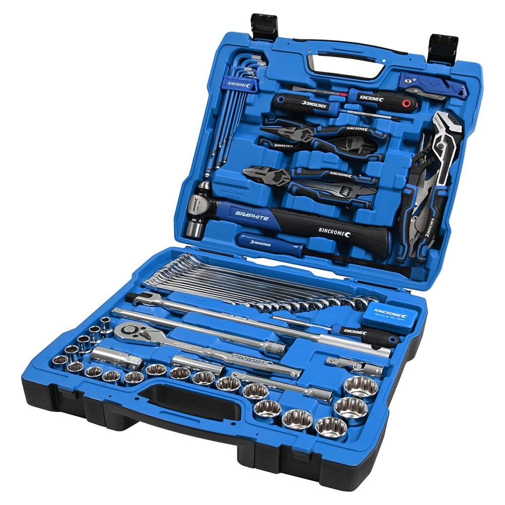
 Title : Ratchet Tool Diagram
Category : Tool Diagram
Format : PDF
Title : Ratchet Tool Diagram
Category : Tool Diagram
Format : PDF