need-3sge-ecu-pinouts-wiring-diagram.pdf
1 / 96
100%
HTTP://MYDIAGRAM.ONLINERevision 1.9 (10/2016)© 2016 HTTP://MYDIAGRAM.ONLINE. All Rights Reserved.
Download Full Diagram Via this App!!!!
Get Diagram Now! DOWNLOAD NOW


.gif)
.gif)


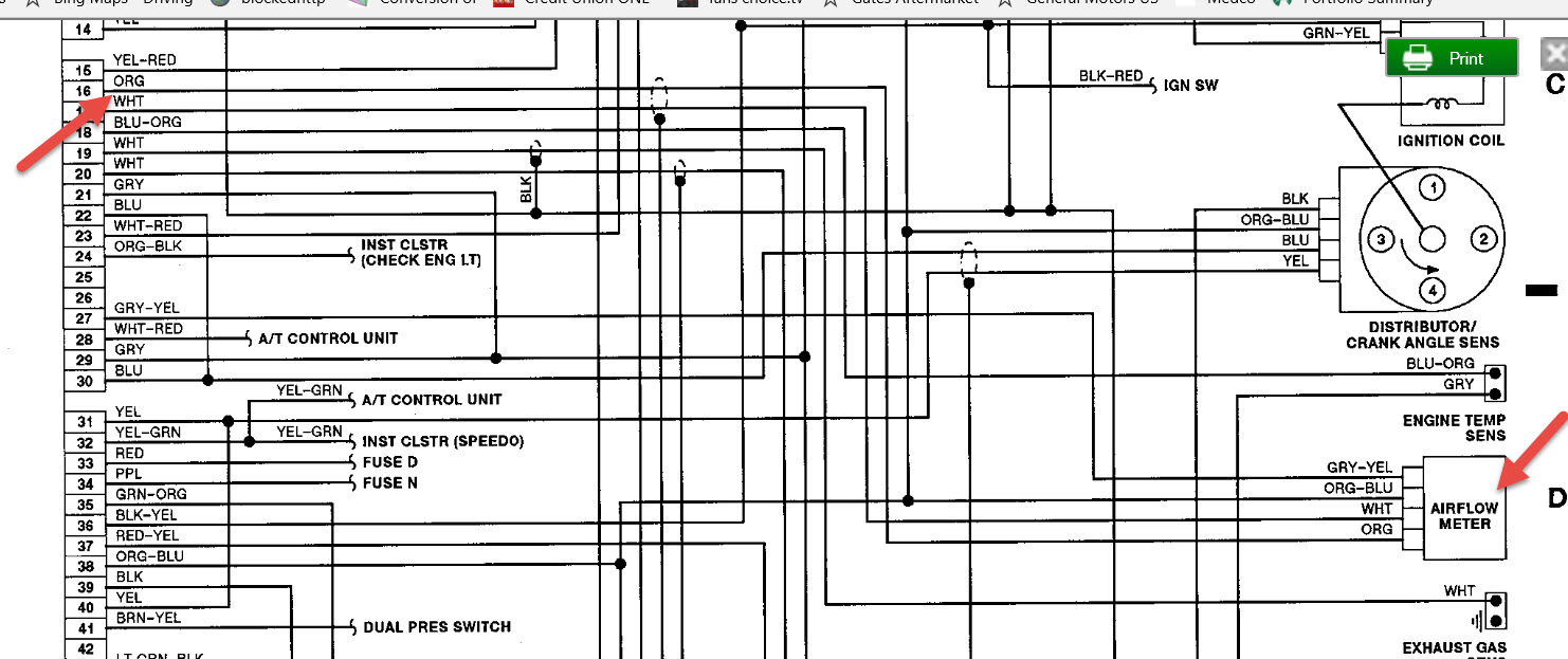
,%20Eprom,%20Map,%20Tuning,%20Pinouts,%20Standalone%20etc/1993%20Eagle%20Talon%20AWD%20Turbo%20ECU%20pinouts.jpg)