manual-hardware-mazda-pnp-wiring-diagram.pdf
1 / 95
100%
Download Full Diagram Via this App!!!!
Get Diagram Now! DOWNLOAD NOW
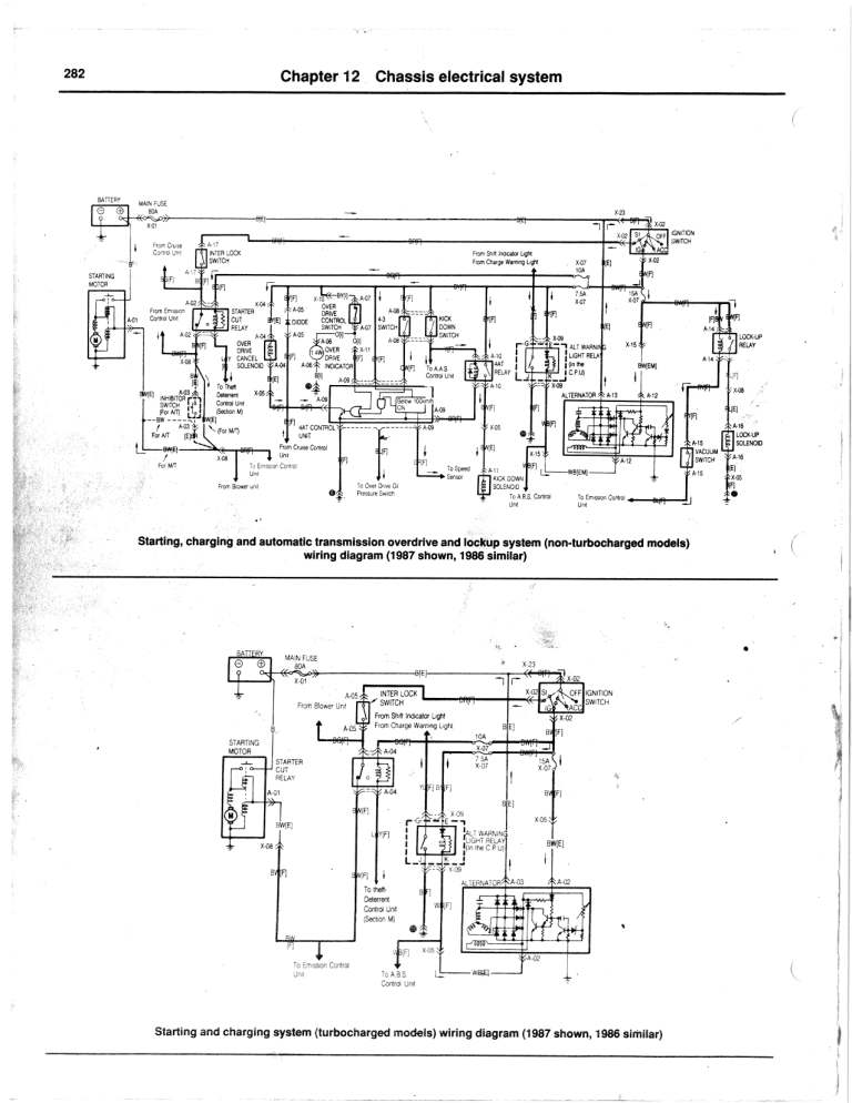
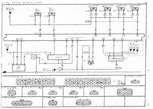 Title : Manual Hardware Mazda Pnp Wiring Diagram
Category : Wiring Diagram
Format : PDF
Title : Manual Hardware Mazda Pnp Wiring Diagram
Category : Wiring Diagram
Format : PDF