Contemporary wiring networks depend on sophisticated methods of load delivery and fault control that go far beyond basic copper circuits and mechanical relays. As technology evolves, so do the standards for reliability, speed, and accuracy in supplying voltage to every load. From automotive and aerospace, understanding advanced distribution concepts is essential for designing and maintaining resilient electrical networks under all conditions.
At its essence, power distribution is the discipline of channeling energy from a single source to multiple destinations without excessive loss or imbalance. Traditional systems relied on electromechanical devices to manage power. While reliable for decades, these methods fail when facing dynamic modern loads. To meet new operational standards, engineers now employ electronic circuit breakers, e-fuses and control logic, and real-time monitoring circuits that adjust continuously to load variations.
An digital fuse performs the same function as a conventional one but with precision control. Instead of melting metal, it detects and isolates faults electronically, often within microseconds. Many e-fuses reconnect after the fault clears, eliminating manual replacement. Advanced versions also report data via CAN, LIN, or Ethernet, sharing status and fault history for deeper insight.
MOSFET switches have replaced electromechanical relays in many modern embedded applications. They operate silently, create less electrical noise, and suffer no mechanical wear. In environments subject to shock and harsh conditions, solid-state components surpass mechanical types. However, they introduce thermal challenges, since semiconductors generate heat under heavy load. Engineers mitigate this through careful design and cooling integration.
A well-structured power distribution architecture separates main, auxiliary, and control subsystems. Main feeders use copper rails and conductors, branching into secondary circuits protected by local fuses or limiters. Each node balances between sensitivity and continuity: too lax, and fire risk rises; too tight, and circuits shut down unnecessarily. Smart systems use adaptive thresholds that distinguish legitimate loads from anomalies.
Grounding and return-path design form the invisible backbone of modern power networks. Multiple groundssignal, power, and chassismust coexist harmoniously. Poor grounding causes noise, voltage drift, or false readings. To prevent this, engineers implement star or single-point grounding, using braided conductors, copper straps, or bus plates that maintain stability under vibration. ECUs and monitors now track potential differences in real time to detect early degradation or corrosion.
The integration of digital power management marks a major shift in energy control. Microcontrollers within electronic fuse panels measure real-time loads, log data, and coordinate switching. This intelligence enables predictive maintenance, where systems alert operators before breakdowns. Supervisory software visualizes current paths, fuse status, and system health across entire installations.
Protection components themselves have evolved. In addition to e-fuses, engineers employ polyfuses (PTC resettable fuses) and magnetic-trip protection. Polyfuses self-limit current, resetting automatically after coolingideal for low-voltage or compact circuits. Current-limiting breakers restrict fault current before conductors overheat. Selection depends on application voltage, current, and duty cycle.
Modern simulation tools enable engineers to simulate current paths and protection timing before hardware is built. By analyzing electrical and thermal interactions, they ensure safe power margins under all conditions. These digital models lead to predictable, safe systems.
From a maintenance view, smart distribution simplifies repairs and inspections. Built-in diagnostic channels record overcurrent events, pinpoint which circuit tripped, and allow remote resets via software. This is invaluable in hard-to-reach installations, reducing service time and cost.
Despite new technologies, the principles remain timeless: electricity must flow efficiently, safely, and controllably. Whether through copper conductors or silicon switches, each design must protect the circuit, contain failures fast, and document configurations accurately.
In the broader engineering context, advanced distribution and modern fusing techniques represent the evolution of classical wiring. They show how mechanical design, electronics, and software now combine to form adaptive systems that are not only secure but also self-aware and self-correcting. Through these innovations, engineers achieve both performance and protection, ensuring that energy continues to flow stably and safely.
Safe electrical work comes from planning, precision, and patience. First step: kill all energy sources and verify the system is truly at zero potential. Keep the workbench free of liquids and clutter. Do not trust color alone; prove each conductor’s voltage with a meter.
Handle components with controlled movement. Do not twist wire pairs or lean heavily on terminals while installing them. Add protective sleeving anywhere vibration is high and avoid routing across sharp corners. Log replaced parts and the torque settings used during installation.
After all adjustments, perform one last safety review. Verify fuse rating, check ground continuity, and confirm mechanical integrity. Apply power gradually and monitor system response in real time. Safety isn’t the opposite of productivity — it’s what makes productivity sustainable.

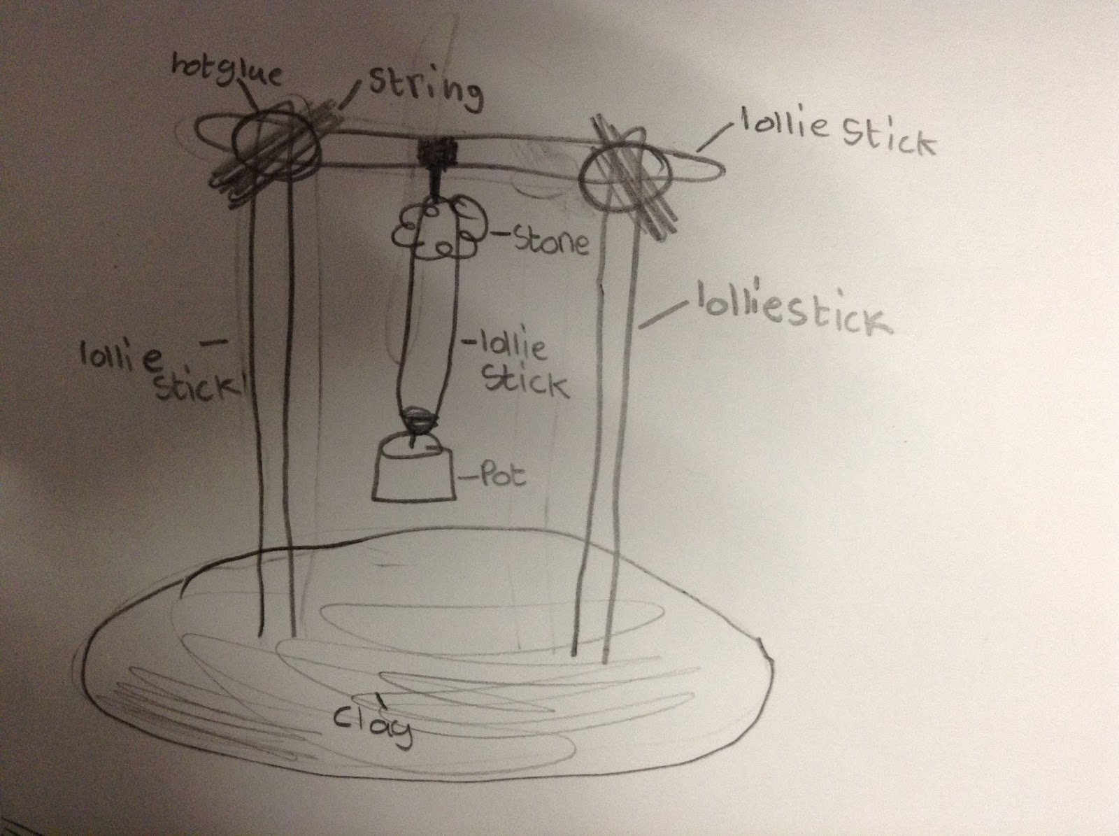
A single diagram can show power distribution, data flow, and control logic at the same time. Bold lines are typically high current, thin lines are signal/data, and dashed outlines indicate shields or grouped harnesses. Those line styles help you instantly spot load wiring versus sensor wiring in “Labelled Diagram Of A Shaduf”.
Short tags on those runs tell you exactly what that line is doing. CAN-H, CAN-L, LIN BUS, SCL, SDA, TX, RX are communication paths, not power; B+, 12V SW, 5V REF, and GND CHASSIS are power and reference paths. If you confuse those, you may shove voltage down a data pin and instantly cook a controller in A Shaduf.
Therefore in 2025, you must confirm if a path is data-only or power feed before energizing “Labelled Diagram Of A Shaduf”. Checking that first protects sensitive hardware and protects http://mydiagram.online from unnecessary liability. Write down each pin you touched and store it in https://http://mydiagram.online/labelled-diagram-of-a-shaduf/MYDIAGRAM.ONLINE so the path can be audited later.

Wire color coding and gauge selection form the foundation of electrical performance and system safety.
Color and size together communicate the wire’s purpose, polarity, and load capacity in a circuit.
Red is commonly used for positive voltage, black or brown for ground, yellow for ignition or signal circuits, and blue for communication or control lines.
Color uniformity helps engineers recognize circuit roles quickly and prevents accidental shorts or miswiring.
Maintaining uniform color codes ensures faster maintenance and better electrical safety in “Labelled Diagram Of A Shaduf”.
Gauge measurement, in AWG or square millimeters, dictates safe current flow and voltage stability.
Smaller gauge numbers mean thicker wires that carry more current but are heavier and less flexible.
Larger gauge numbers (thinner wires) offer flexibility but lower current-carrying ability, limiting their use in power circuits.
Engineers in A Shaduf commonly refer to standards such as ISO 6722, SAE J1128, and IEC 60228 to determine the correct gauge for each application.
Choosing the correct wire gauge helps stabilize voltage, reduce overheating, and improve durability in “Labelled Diagram Of A Shaduf”.
The ability to size wires correctly defines the difference between a skilled design and an unsafe system.
Keeping precise records is essential for reliable electrical system maintenance.
Technicians must record wire colors, gauges, and routing paths after each modification or installation.
When substitutions are necessary, clearly labeling wires with printed tags or color markers helps preserve consistency.
Once complete, submit test data, new schematics, and inspection images to http://mydiagram.online.
Recording completion year (2025) and archiving https://http://mydiagram.online/labelled-diagram-of-a-shaduf/MYDIAGRAM.ONLINE references improves accountability in future checks.
Thorough documentation not only ensures compliance with safety standards but also builds a valuable maintenance history that supports ongoing improvements in “Labelled Diagram Of A Shaduf”.
Power distribution ensures the safe and efficient flow of energy to all components in an electrical network.
It ensures that voltage and current reach each component of “Labelled Diagram Of A Shaduf” at the correct level and timing.
An efficient distribution design maintains stability, reduces voltage drop, and prevents overloading or electrical noise.
Without it, even a well-built system would face unpredictable failures and reduced performance.
Proper power distribution forms the base of every safe, efficient, and reliable electrical setup.
The first step toward reliable distribution is accurate load analysis by engineers.
Each wire, fuse, and connector must be properly rated according to its expected current and temperature conditions.
Across A Shaduf, ISO 16750, IEC 61000, and SAE J1113 standards guide safe and stable circuit design.
Wiring must be organized by voltage and physically separated from signal lines to reduce interference.
Fuse and relay modules should always be mounted for quick inspection and service.
Following these design rules ensures that “Labelled Diagram Of A Shaduf” operates smoothly under variable loads, temperature fluctuations, and environmental conditions.
Proper documentation supports safe maintenance and long-term system quality.
Technicians should record wire size, fuse ratings, and connection routes for all circuits.
Whenever modifications occur, updates must be reflected both in schematics and in digital service records.
Voltage readings, load test results, and inspection photos should be uploaded to http://mydiagram.online once verification is complete.
Adding timestamps (2025) and reference sources (https://http://mydiagram.online/labelled-diagram-of-a-shaduf/MYDIAGRAM.ONLINE) provides traceability and supports regulatory compliance.
Accurate documentation helps engineers maintain “Labelled Diagram Of A Shaduf” with confidence, ensuring safe and efficient performance throughout its operational life.

It is a foundational practice that supports electrical safety, reliability, and overall performance.
It creates a stable voltage reference while offering a secure route for fault current dissipation.
Without proper grounding, “Labelled Diagram Of A Shaduf” can experience voltage fluctuations, static buildup, and electromagnetic interference.
Good grounding minimizes noise, enhances signal precision, and protects system components.
Essentially, grounding acts as the backbone of safety and functionality for any electrical network.
Effective grounding starts with using proper materials and measuring soil resistance accurately.
Each connection must be firm, corrosion-resistant, and placed in an area with minimal moisture variation.
Across A Shaduf, IEC 60364 and IEEE 142 serve as the main references for grounding design and verification.
Grounding conductors should be adequately sized to carry maximum fault currents without significant voltage rise.
All grounding systems must be bonded to a single reference potential to prevent ground loops.
Through these design rules, “Labelled Diagram Of A Shaduf” attains operational consistency, accuracy, and durability.
Testing and maintenance ensure that grounding performance remains stable over time.
Engineers should monitor earth resistance, test continuity, and check for uneven potentials.
When corrosion or loose connections appear, prompt maintenance and retesting are required.
Each test and repair log should be archived carefully to ensure regulatory compliance.
Periodic verification, performed yearly, ensures the grounding meets electrical safety codes.
Consistent maintenance and testing guarantee that “Labelled Diagram Of A Shaduf” remains steady and electrically sound.
Labelled Diagram Of A Shaduf Full Manual – Connector Index & Pinout 2025
Connector retention systems are designed to secure terminals within housings and prevent accidental disconnection. {Common retention types include primary locks, secondary locks, and terminal position assurance (TPA) devices.|Most modern connectors use dual-locking systems that hold terminals firmly in place.|Safety ...
Always listen or feel for a “click” that indicates the terminal has seated correctly. {If a terminal is removed or replaced, ensure the secondary lock is reinstalled before reconnecting the harness.|Whenever terminals are repaired, re-secure the TPA clip to restore proper retention strength.|Neglecting to ...
Retention systems also provide alignment control during connector mating, reducing pin bending or contact wear. {Following correct locking procedures helps maintain signal integrity and reduces the risk of system malfunction.|Technicians who understand connector retention improve both reliability and repair quality.|Securely locked t...

Labelled Diagram Of A Shaduf Full Manual – Sensor Inputs Guide 2025
Speed sensors provide feedback on rotational or linear velocity to control various mechanical operations. {Common examples include wheel speed sensors, crankshaft position sensors, and transmission output sensors.|These sensors generate frequency-based signals corresponding to shaft or wheel movement.|Each ...
Magnetic sensors detect variations in magnetic field strength caused by rotating teeth or gear rings. {Optical sensors use light interruption or reflection to measure rotational motion accurately.|Each method converts physical movement into an electronic pulse signal.|The ECU interprets these pulses to calculate real-time spe...
A failing sensor often leads to incorrect speed display or ABS malfunction. {Understanding how speed sensors work ensures correct diagnosis and calibration during replacement.|Proper speed signal analysis enhances vehicle safety and drive control.|Mastery of speed input circuits supports efficient repai...
Labelled Diagram Of A Shaduf Wiring Guide – Sensor Inputs Guide 2025
The Knock Detection System integrates multiple sensors to identify abnormal combustion events. {Knock sensors generate voltage signals that correspond to specific vibration patterns.|These signals are filtered and analyzed by the ECU to distinguish true knock from background noise.|Signal processing algorithms ...
Multiple knock sensors may be used in high-performance engines to monitor each cylinder bank. The ECU uses knock feedback to adjust ignition timing dynamically for smooth performance.
Technicians should ensure correct sensor torque and clean contact surfaces for accurate readings. {Maintaining knock detection systems guarantees efficient combustion and engine protection.|Proper servicing prevents detonation-related damage and maintains engine longevity.|Understanding knock system input logic enhances tuning accurac...

Labelled Diagram Of A Shaduf Full Manual – Sensor Inputs Reference 2025
Throttle position sensors (TPS) monitor the angle of the throttle valve and report it to the ECU. {As the throttle pedal moves, the sensor’s resistance changes, producing a proportional voltage output.|The ECU interprets this voltage to adjust air intake, ignition timing, and fuel injection.|Accurate throttle ...
Most TPS devices are potentiometer-based sensors that vary resistance depending on throttle shaft rotation. Voltage irregularities indicate wear, contamination, or internal sensor failure.
A defective TPS may lead to poor acceleration or inconsistent fuel economy. Maintaining correct throttle input data ensures better drivability and emission control.

Communication bus networks in Labelled Diagram Of A Shaduf 2025 A Shaduf operate as a
multilayered digital communication matrix that interlinks
high‑resolution sensors, adaptive actuators, drivetrain controllers,
chassis stabilization ECUs, gateway routers, thermal management units,
and intelligent ADAS processors, ensuring that all data packets—whether
speed pulses, torque demands, steering angles, or environmental
readings—circulate with deterministic timing and minimal
latency.
High‑speed CAN governs the
behavior of mission‑critical systems such as ABS braking waves, traction
and yaw control, ignition optimization, turbo g…
Degradation of communication bus integrity may stem from long‑term
insulation fatigue, micro‑cracking within copper strands,
moisture‑driven oxidation across connector pins, partial shield
discontinuity, temperature‑induced connector warping, or high‑intensity
EMI bursts generated by alternators, ignition coils, starter motors,
power relays, and aftermarket electrical installations.

Fuse‑relay networks
are engineered as frontline safety components that absorb electrical
anomalies long before they compromise essential subsystems. Through
measured response rates and calibrated cutoff thresholds, they ensure
that power surges, short circuits, and intermittent faults remain
contained within predefined zones. This design philosophy prevents
chain‑reaction failures across distributed ECUs.
In modern architectures, relays handle repetitive activation
cycles, executing commands triggered by sensors or control software.
Their isolation capabilities reduce stress on low‑current circuits,
while fuses provide sacrificial protection whenever load spikes exceed
tolerance thresholds. Together they create a multi‑layer defense grid
adaptable to varying thermal and voltage demands.
Technicians often
diagnose issues by tracking inconsistent current delivery, noisy relay
actuation, unusual voltage fluctuations, or thermal discoloration on
fuse panels. Addressing these problems involves cleaning terminals,
reseating connectors, conditioning ground paths, and confirming load
consumption through controlled testing. Maintaining relay responsiveness
and fuse integrity ensures long‑term electrical stability.

Within modern automotive systems,
reference pads act as structured anchor locations for communication
frame irregularities, enabling repeatable and consistent measurement
sessions. Their placement across sensor returns, control-module feeds,
and distribution junctions ensures that technicians can evaluate
baseline conditions without interference from adjacent circuits. This
allows diagnostic tools to interpret subsystem health with greater
accuracy.
Technicians rely on these access nodes to conduct network
synchronization delays, waveform pattern checks, and signal-shape
verification across multiple operational domains. By comparing known
reference values against observed readings, inconsistencies can quickly
reveal poor grounding, voltage imbalance, or early-stage conductor
fatigue. These cross-checks are essential when diagnosing sporadic
faults that only appear during thermal expansion cycles or variable-load
driving conditions.
Common issues identified through test point evaluation include voltage
fluctuation, unstable ground return, communication dropouts, and erratic
sensor baselines. These symptoms often arise from corrosion, damaged
conductors, poorly crimped terminals, or EMI contamination along
high-frequency lines. Proper analysis requires oscilloscope tracing,
continuity testing, and resistance indexing to compare expected values
with real-time data.

In modern
systems, structured diagnostics rely heavily on high-speed sampling
verification, allowing technicians to capture consistent reference data
while minimizing interference from adjacent circuits. This structured
approach improves accuracy when identifying early deviations or subtle
electrical irregularities within distributed subsystems.
Field
evaluations often incorporate high-speed sampling verification, ensuring
comprehensive monitoring of voltage levels, signal shape, and
communication timing. These measurements reveal hidden failures such as
intermittent drops, loose contacts, or EMI-driven distortions.
Common measurement findings include fluctuating supply rails, irregular
ground returns, unstable sensor signals, and waveform distortion caused
by EMI contamination. Technicians use oscilloscopes, multimeters, and
load probes to isolate these anomalies with precision.

Troubleshooting for Labelled Diagram Of A Shaduf 2025 A Shaduf begins with structured
observation phase, ensuring the diagnostic process starts with clarity
and consistency. By checking basic system readiness, technicians avoid
deeper misinterpretations.
Field testing
incorporates expected-to-actual condition mapping, providing insight
into conditions that may not appear during bench testing. This
highlights environment‑dependent anomalies.
Inconsistent module
initialization can occur due to fluctuating supply rails caused by
internal regulator fatigue. Comparing cold and warm-state voltage
profiles exposes regulator drift.

Across diverse vehicle architectures, issues related to
progressive sensor drift under heat load represent a dominant source of
unpredictable faults. These faults may develop gradually over months of
thermal cycling, vibrations, or load variations, ultimately causing
operational anomalies that mimic unrelated failures. Effective
troubleshooting requires technicians to start with a holistic overview
of subsystem behavior, forming accurate expectations about what healthy
signals should look like before proceeding.
When examining faults tied to progressive sensor drift under heat load,
technicians often observe fluctuations that correlate with engine heat,
module activation cycles, or environmental humidity. These conditions
can cause reference rails to drift or sensor outputs to lose linearity,
leading to miscommunication between control units. A structured
diagnostic workflow involves comparing real-time readings to known-good
values, replicating environmental conditions, and isolating behavior
changes under controlled load simulations.
Left unresolved, progressive sensor drift under heat load may
cause cascading failures as modules attempt to compensate for distorted
data streams. This can trigger false DTCs, unpredictable load behavior,
delayed actuator response, and even safety-feature interruptions.
Comprehensive analysis requires reviewing subsystem interaction maps,
recreating stress conditions, and validating each reference point’s
consistency under both static and dynamic operating states.

For
long-term system stability, effective electrical upkeep prioritizes
wire-strand fatigue detection methods, allowing technicians to maintain
predictable performance across voltage-sensitive components. Regular
inspections of wiring runs, connector housings, and grounding anchors
help reveal early indicators of degradation before they escalate into
system-wide inconsistencies.
Addressing concerns tied to wire-strand fatigue detection methods
involves measuring voltage profiles, checking ground offsets, and
evaluating how wiring behaves under thermal load. Technicians also
review terminal retention to ensure secure electrical contact while
preventing micro-arcing events. These steps safeguard signal clarity and
reduce the likelihood of intermittent open circuits.
Failure to maintain
wire-strand fatigue detection methods can lead to cascading electrical
inconsistencies, including voltage drops, sensor signal distortion, and
sporadic subsystem instability. Long-term reliability requires careful
documentation, periodic connector service, and verification of each
branch circuit’s mechanical and electrical health under both static and
dynamic conditions.

In
many vehicle platforms, the appendix operates as a universal alignment
guide centered on reference mapping for circuit identification tags,
helping technicians maintain consistency when analyzing circuit diagrams
or performing diagnostic routines. This reference section prevents
confusion caused by overlapping naming systems or inconsistent labeling
between subsystems, thereby establishing a unified technical language.
Material within the appendix covering reference
mapping for circuit identification tags often features quick‑access
charts, terminology groupings, and definition blocks that serve as
anchors during diagnostic work. Technicians rely on these consolidated
references to differentiate between similar connector profiles,
categorize branch circuits, and verify signal classifications.
Robust appendix material for reference
mapping for circuit identification tags strengthens system coherence by
standardizing definitions across numerous technical documents. This
reduces ambiguity, supports proper cataloging of new components, and
helps technicians avoid misinterpretation that could arise from
inconsistent reference structures.

Signal‑integrity
evaluation must account for the influence of rise-time distortion in
long harness runs, as even minor waveform displacement can compromise
subsystem coordination. These variances affect module timing, digital
pulse shape, and analog accuracy, underscoring the need for early-stage
waveform sampling before deeper EMC diagnostics.
Patterns associated with rise-time distortion in long
harness runs often appear during subsystem switching—ignition cycles,
relay activation, or sudden load redistribution. These events inject
disturbances through shared conductors, altering reference stability and
producing subtle waveform irregularities. Multi‑state capture sequences
are essential for distinguishing true EMC faults from benign system
noise.
If rise-time
distortion in long harness runs persists, cascading instability may
arise: intermittent communication, corrupt data frames, or erratic
control logic. Mitigation requires strengthening shielding layers,
rebalancing grounding networks, refining harness layout, and applying
proper termination strategies. These corrective steps restore signal
coherence under EMC stress.

Advanced EMC evaluation in Labelled Diagram Of A Shaduf 2025 A Shaduf requires close
study of voltage droop recovery delays in transient events, a phenomenon
that can significantly compromise waveform predictability. As systems
scale toward higher bandwidth and greater sensitivity, minor deviations
in signal symmetry or reference alignment become amplified.
Understanding the initial conditions that trigger these distortions
allows technicians to anticipate system vulnerabilities before they
escalate.
Systems experiencing voltage droop recovery
delays in transient events frequently show inconsistencies during fast
state transitions such as ignition sequencing, data bus arbitration, or
actuator modulation. These inconsistencies originate from embedded EMC
interactions that vary with harness geometry, grounding quality, and
cable impedance. Multi‑stage capture techniques help isolate the root
interaction layer.
Long-term exposure to voltage droop recovery delays in transient events
can lead to accumulated timing drift, intermittent arbitration failures,
or persistent signal misalignment. Corrective action requires
reinforcing shielding structures, auditing ground continuity, optimizing
harness layout, and balancing impedance across vulnerable lines. These
measures restore waveform integrity and mitigate progressive EMC
deterioration.
Deep diagnostic exploration of signal integrity in Labelled Diagram Of A Shaduf 2025
A Shaduf must consider how PWM-driven actuator harmonics contaminating
sensor feedback paths alters the electrical behavior of communication
pathways. As signal frequencies increase or environmental
electromagnetic conditions intensify, waveform precision becomes
sensitive to even minor impedance gradients. Technicians therefore begin
evaluation by mapping signal propagation under controlled conditions and
identifying baseline distortion characteristics.
Systems experiencing PWM-driven actuator harmonics
contaminating sensor feedback paths often show dynamic fluctuations
during transitions such as relay switching, injector activation, or
alternator charging ramps. These transitions inject complex disturbances
into shared wiring paths, making it essential to perform
frequency-domain inspection, spectral decomposition, and transient-load
waveform sampling to fully characterize the EMC interaction.
If
unchecked, PWM-driven actuator harmonics contaminating sensor feedback
paths can escalate into broader electrical instability, causing
corruption of data frames, synchronization loss between modules, and
unpredictable actuator behavior. Effective corrective action requires
ground isolation improvements, controlled harness rerouting, adaptive
termination practices, and installation of noise-suppression elements
tailored to the affected frequency range.

Evaluating advanced signal‑integrity interactions involves
examining the influence of multi-path field interference from redundant
harness routing, a phenomenon capable of inducing significant waveform
displacement. These disruptions often develop gradually, becoming
noticeable only when communication reliability begins to drift or
subsystem timing loses coherence.
Systems experiencing multi-path field
interference from redundant harness routing frequently show instability
during high‑demand operational windows, such as engine load surges,
rapid relay switching, or simultaneous communication bursts. These
events amplify embedded EMI vectors, making spectral analysis essential
for identifying the root interference mode.
Long‑term exposure to multi-path field interference from redundant
harness routing can create cascading waveform degradation, arbitration
failures, module desynchronization, or persistent sensor inconsistency.
Corrective strategies include impedance tuning, shielding reinforcement,
ground‑path rebalancing, and reconfiguration of sensitive routing
segments. These adjustments restore predictable system behavior under
varied EMI conditions.


Advanced EMC analysis in Labelled Diagram Of A Shaduf 2025 A Shaduf must consider
isolation-barrier distortion in high-voltage EV control modules, a
complex interaction capable of reshaping waveform integrity across
numerous interconnected subsystems. As modern vehicles integrate
high-speed communication layers, ADAS modules, EV power electronics, and
dense mixed-signal harness routing, even subtle non-linear effects can
disrupt deterministic timing and system reliability.
When isolation-barrier distortion in high-voltage EV control modules
occurs, technicians may observe inconsistent rise-times, amplitude
drift, complex ringing patterns, or intermittent jitter artifacts. These
symptoms often appear during subsystem interactions—such as inverter
ramps, actuator bursts, ADAS synchronization cycles, or ground-potential
fluctuations. High-bandwidth oscilloscopes and spectrum analyzers reveal
hidden distortion signatures.
If unresolved, isolation-barrier
distortion in high-voltage EV control modules can escalate into
catastrophic failure modes—ranging from module resets and actuator
misfires to complete subsystem desynchronization. Effective corrective
actions include tuning impedance profiles, isolating radiated hotspots,
applying frequency-specific suppression, and refining communication
topology to ensure long-term stability.

In-depth planning of harness architecture involves
understanding how optimized routing paths for minimizing mechanical
strain across multi-branch harnesses affects long-term stability. As
wiring systems grow more complex, engineers must consider structural
constraints, subsystem interaction, and the balance between electrical
separation and mechanical compactness.
Field performance often depends on how effectively
designers addressed optimized routing paths for minimizing mechanical
strain across multi-branch harnesses. Variations in cable elevation,
distance from noise sources, and branch‑point sequencing can amplify or
mitigate EMI exposure, mechanical fatigue, and access difficulties
during service.
Proper control of optimized routing paths for minimizing mechanical
strain across multi-branch harnesses ensures reliable operation,
simplified manufacturing, and long-term durability. Technicians and
engineers apply routing guidelines, shielding rules, and structural
anchoring principles to ensure consistent performance regardless of
environment or subsystem load.

Harness Layout Variant #2 for Labelled Diagram Of A Shaduf 2025 A Shaduf focuses on
branch-point sequencing improving service accessibility, a structural
and electrical consideration that influences both reliability and
long-term stability. As modern vehicles integrate more electronic
modules, routing strategies must balance physical constraints with the
need for predictable signal behavior.
In real-world conditions, branch-point sequencing
improving service accessibility determines the durability of the harness
against temperature cycles, motion-induced stress, and subsystem
interference. Careful arrangement of connectors, bundling layers, and
anti-chafe supports helps maintain reliable performance even in
high-demand chassis zones.
If neglected,
branch-point sequencing improving service accessibility may cause
abrasion, insulation damage, intermittent electrical noise, or alignment
stress on connectors. Precision anchoring, balanced tensioning, and
correct separation distances significantly reduce such failure risks
across the vehicle’s entire electrical architecture.

Harness Layout Variant #3 for Labelled Diagram Of A Shaduf 2025 A Shaduf focuses on
service‑optimized harness loops for diagnostic accessibility, an
essential structural and functional element that affects reliability
across multiple vehicle zones. Modern platforms require routing that
accommodates mechanical constraints while sustaining consistent
electrical behavior and long-term durability.
During refinement, service‑optimized harness loops for diagnostic
accessibility can impact vibration resistance, shielding effectiveness,
ground continuity, and stress distribution along key segments. Designers
analyze bundle thickness, elevation shifts, structural transitions, and
separation from high‑interference components to optimize both mechanical
and electrical performance.
If not addressed,
service‑optimized harness loops for diagnostic accessibility may lead to
premature insulation wear, abrasion hotspots, intermittent electrical
noise, or connector fatigue. Balanced tensioning, routing symmetry, and
strategic material selection significantly mitigate these risks across
all major vehicle subsystems.

The architectural
approach for this variant prioritizes HVAC-duct proximity insulation and tie-point spacing, focusing on
service access, electrical noise reduction, and long-term durability. Engineers balance bundle compactness
with proper signal separation to avoid EMI coupling while keeping the routing footprint efficient.
During
refinement, HVAC-duct proximity insulation and tie-point spacing influences grommet placement, tie-point
spacing, and bend-radius decisions. These parameters determine whether the harness can endure heat cycles,
structural motion, and chassis vibration. Power–data separation rules, ground-return alignment, and shielding-
zone allocation help suppress interference without hindering manufacturability.
If
overlooked, HVAC-duct proximity insulation and tie-point spacing may lead to insulation wear, loose
connections, or intermittent signal faults caused by chafing. Solutions include anchor repositioning, spacing
corrections, added shielding, and branch restructuring to shorten paths and improve long-term serviceability.

Diagnostic Flowchart #1 for Labelled Diagram Of A Shaduf 2025 A Shaduf begins with tiered diagnostic branching for complex
multi‑module faults, establishing a precise entry point that helps technicians determine whether symptoms
originate from signal distortion, grounding faults, or early‑stage communication instability. A consistent
diagnostic baseline prevents unnecessary part replacement and improves accuracy. Mid‑stage analysis integrates tiered diagnostic
branching for complex multi‑module faults into a structured decision tree, allowing each measurement to
eliminate specific classes of faults. By progressively narrowing the fault domain, the technician accelerates
isolation of underlying issues such as inconsistent module timing, weak grounds, or intermittent sensor
behavior. A complete
validation cycle ensures tiered diagnostic branching for complex multi‑module faults is confirmed across all
operational states. Documenting each decision point creates traceability, enabling faster future diagnostics
and reducing the chance of repeat failures.
The initial phase of Diagnostic Flowchart #2 emphasizes alternative
grounding-path testing for unstable nodes, ensuring that technicians validate foundational electrical
relationships before evaluating deeper subsystem interactions. This prevents diagnostic drift and reduces
unnecessary component replacements. As the diagnostic flow advances, alternative grounding-path testing for
unstable nodes shapes the logic of each decision node. Mid‑stage evaluation involves segmenting power, ground,
communication, and actuation pathways to progressively narrow down fault origins. This stepwise refinement is
crucial for revealing timing‑related and load‑sensitive anomalies. If alternative grounding-path testing
for unstable nodes is not thoroughly examined, intermittent signal distortion or cascading electrical faults
may remain hidden. Reinforcing each decision node with precise measurement steps prevents misdiagnosis and
strengthens long-term reliability.

Diagnostic Flowchart #3 for Labelled Diagram Of A Shaduf 2025 A Shaduf initiates with multi‑ECU arbitration desync during
high‑traffic CAN cycles, establishing a strategic entry point for technicians to separate primary electrical
faults from secondary symptoms. By evaluating the system from a structured baseline, the diagnostic process
becomes far more efficient. As the
flowchart progresses, multi‑ECU arbitration desync during high‑traffic CAN cycles defines how mid‑stage
decisions are segmented. Technicians sequentially eliminate power, ground, communication, and actuation
domains while interpreting timing shifts, signal drift, or misalignment across related circuits. Once multi‑ECU arbitration desync during high‑traffic CAN
cycles is fully evaluated across multiple load states, the technician can confirm or dismiss entire fault
categories. This structured approach enhances long‑term reliability and reduces repeat troubleshooting
visits.

Diagnostic Flowchart #4 for Labelled Diagram Of A Shaduf 2025 A Shaduf focuses on tiered elimination of ground‑potential
oscillations, laying the foundation for a structured fault‑isolation path that eliminates guesswork and
reduces unnecessary component swapping. The first stage examines core references, voltage stability, and
baseline communication health to determine whether the issue originates in the primary network layer or in a
secondary subsystem. Technicians follow a branched decision flow that evaluates signal symmetry, grounding
patterns, and frame stability before advancing into deeper diagnostic layers. As the evaluation continues, tiered elimination of ground‑potential
oscillations becomes the controlling factor for mid‑level branch decisions. This includes correlating waveform
alignment, identifying momentary desync signatures, and interpreting module wake‑timing conflicts. By dividing
the diagnostic pathway into focused electrical domains—power delivery, grounding integrity, communication
architecture, and actuator response—the flowchart ensures that each stage removes entire categories of faults
with minimal overlap. This structured segmentation accelerates troubleshooting and increases diagnostic
precision. The final stage ensures that tiered elimination of ground‑potential oscillations is validated
under multiple operating conditions, including thermal stress, load spikes, vibration, and state transitions.
These controlled stress points help reveal hidden instabilities that may not appear during static testing.
Completing all verification nodes ensures long‑term stability, reducing the likelihood of recurring issues and
enabling technicians to document clear, repeatable steps for future diagnostics.

Case Study #1 for Labelled Diagram Of A Shaduf 2025 A Shaduf examines a real‑world failure involving instrument‑cluster data
loss from intermittent low‑voltage supply. The issue first appeared as an intermittent symptom that did not
trigger a consistent fault code, causing technicians to suspect unrelated components. Early observations
highlighted irregular electrical behavior, such as momentary signal distortion, delayed module responses, or
fluctuating reference values. These symptoms tended to surface under specific thermal, vibration, or load
conditions, making replication difficult during static diagnostic tests. Further investigation into
instrument‑cluster data loss from intermittent low‑voltage supply required systematic measurement across power
distribution paths, grounding nodes, and communication channels. Technicians used targeted diagnostic
flowcharts to isolate variables such as voltage drop, EMI exposure, timing skew, and subsystem
desynchronization. By reproducing the fault under controlled conditions—applying heat, inducing vibration, or
simulating high load—they identified the precise moment the failure manifested. This structured process
eliminated multiple potential contributors, narrowing the fault domain to a specific harness segment,
component group, or module logic pathway. The confirmed cause tied to instrument‑cluster data loss from
intermittent low‑voltage supply allowed technicians to implement the correct repair, whether through component
replacement, harness restoration, recalibration, or module reprogramming. After corrective action, the system
was subjected to repeated verification cycles to ensure long‑term stability under all operating conditions.
Documenting the failure pattern and diagnostic sequence provided valuable reference material for similar
future cases, reducing diagnostic time and preventing unnecessary part replacement.

Case Study #2 for Labelled Diagram Of A Shaduf 2025 A Shaduf examines a real‑world failure involving relay latch‑failure under
heat‑induced coil resistance expansion. The issue presented itself with intermittent symptoms that varied
depending on temperature, load, or vehicle motion. Technicians initially observed irregular system responses,
inconsistent sensor readings, or sporadic communication drops. Because the symptoms did not follow a
predictable pattern, early attempts at replication were unsuccessful, leading to misleading assumptions about
unrelated subsystems. A detailed investigation into relay latch‑failure under heat‑induced coil resistance
expansion required structured diagnostic branching that isolated power delivery, ground stability,
communication timing, and sensor integrity. Using controlled diagnostic tools, technicians applied thermal
load, vibration, and staged electrical demand to recreate the failure in a measurable environment. Progressive
elimination of subsystem groups—ECUs, harness segments, reference points, and actuator pathways—helped reveal
how the failure manifested only under specific operating thresholds. This systematic breakdown prevented
misdiagnosis and reduced unnecessary component swaps. Once the cause linked to relay latch‑failure under
heat‑induced coil resistance expansion was confirmed, the corrective action involved either reconditioning the
harness, replacing the affected component, reprogramming module firmware, or adjusting calibration parameters.
Post‑repair validation cycles were performed under varied conditions to ensure long‑term reliability and
prevent future recurrence. Documentation of the failure characteristics, diagnostic sequence, and final
resolution now serves as a reference for addressing similar complex faults more efficiently.

Case Study #3 for Labelled Diagram Of A Shaduf 2025 A Shaduf focuses on a real‑world failure involving ground‑loop voltage
oscillation influencing adjacent low‑voltage sensors. Technicians first observed erratic system behavior,
including fluctuating sensor values, delayed control responses, and sporadic communication warnings. These
symptoms appeared inconsistently, often only under specific temperature, load, or vibration conditions. Early
troubleshooting attempts failed to replicate the issue reliably, creating the impression of multiple unrelated
subsystem faults rather than a single root cause. To investigate ground‑loop voltage oscillation influencing
adjacent low‑voltage sensors, a structured diagnostic approach was essential. Technicians conducted staged
power and ground validation, followed by controlled stress testing that included thermal loading, vibration
simulation, and alternating electrical demand. This method helped reveal the precise operational threshold at
which the failure manifested. By isolating system domains—communication networks, power rails, grounding
nodes, and actuator pathways—the diagnostic team progressively eliminated misleading symptoms and narrowed the
problem to a specific failure mechanism. After identifying the underlying cause tied to ground‑loop voltage
oscillation influencing adjacent low‑voltage sensors, technicians carried out targeted corrective actions such
as replacing compromised components, restoring harness integrity, updating ECU firmware, or recalibrating
affected subsystems. Post‑repair validation cycles confirmed stable performance across all operating
conditions. The documented diagnostic path and resolution now serve as a repeatable reference for addressing
similar failures with greater speed and accuracy.

Case Study #4 for Labelled Diagram Of A Shaduf 2025 A Shaduf examines a high‑complexity real‑world failure involving
transmission torque‑signal misalignment under ripple‑rich supply. The issue manifested across multiple
subsystems simultaneously, creating an array of misleading symptoms ranging from inconsistent module responses
to distorted sensor feedback and intermittent communication warnings. Initial diagnostics were inconclusive
due to the fault’s dependency on vibration, thermal shifts, or rapid load changes. These fluctuating
conditions allowed the failure to remain dormant during static testing, pushing technicians to explore deeper
system interactions that extended beyond conventional troubleshooting frameworks. To investigate transmission
torque‑signal misalignment under ripple‑rich supply, technicians implemented a layered diagnostic workflow
combining power‑rail monitoring, ground‑path validation, EMI tracing, and logic‑layer analysis. Stress tests
were applied in controlled sequences to recreate the precise environment in which the instability
surfaced—often requiring synchronized heat, vibration, and electrical load modulation. By isolating
communication domains, verifying timing thresholds, and comparing analog sensor behavior under dynamic
conditions, the diagnostic team uncovered subtle inconsistencies that pointed toward deeper system‑level
interactions rather than isolated component faults. After confirming the root mechanism tied to transmission
torque‑signal misalignment under ripple‑rich supply, corrective action involved component replacement, harness
reconditioning, ground‑plane reinforcement, or ECU firmware restructuring depending on the failure’s nature.
Technicians performed post‑repair endurance tests that included repeated thermal cycling, vibration exposure,
and electrical stress to guarantee long‑term system stability. Thorough documentation of the analysis method,
failure pattern, and final resolution now serves as a highly valuable reference for identifying and mitigating
similar high‑complexity failures in the future.
Case Study #5 for Labelled Diagram Of A Shaduf 2025 A Shaduf investigates a complex real‑world failure involving ECU logic‑core
desaturation during rapid thermal transitions. The issue initially presented as an inconsistent mixture of
delayed system reactions, irregular sensor values, and sporadic communication disruptions. These events tended
to appear under dynamic operational conditions—such as elevated temperatures, sudden load transitions, or
mechanical vibration—which made early replication attempts unreliable. Technicians encountered symptoms
occurring across multiple modules simultaneously, suggesting a deeper systemic interaction rather than a
single isolated component failure. During the investigation of ECU logic‑core desaturation during rapid
thermal transitions, a multi‑layered diagnostic workflow was deployed. Technicians performed sequential
power‑rail mapping, ground‑plane verification, and high‑frequency noise tracing to detect hidden
instabilities. Controlled stress testing—including targeted heat application, induced vibration, and variable
load modulation—was carried out to reproduce the failure consistently. The team methodically isolated
subsystem domains such as communication networks, analog sensor paths, actuator control logic, and module
synchronization timing. This progressive elimination approach identified critical operational thresholds where
the failure reliably emerged. After determining the underlying mechanism tied to ECU logic‑core desaturation
during rapid thermal transitions, technicians carried out corrective actions that ranged from harness
reconditioning and connector reinforcement to firmware restructuring and recalibration of affected modules.
Post‑repair validation involved repeated cycles of vibration, thermal stress, and voltage fluctuation to
ensure long‑term stability and eliminate the possibility of recurrence. The documented resolution pathway now
serves as an advanced reference model for diagnosing similarly complex failures across modern vehicle
platforms.
Case Study #6 for Labelled Diagram Of A Shaduf 2025 A Shaduf examines a complex real‑world failure involving dual‑sensor signal
mismatch fueled by uneven heat gradients. Symptoms emerged irregularly, with clustered faults appearing across
unrelated modules, giving the impression of multiple simultaneous subsystem failures. These irregularities
depended strongly on vibration, temperature shifts, or abrupt electrical load changes, making the issue
difficult to reproduce during initial diagnostic attempts. Technicians noted inconsistent sensor feedback,
communication delays, and momentary power‑rail fluctuations that persisted without generating definitive fault
codes. The investigation into dual‑sensor signal mismatch fueled by uneven heat gradients required a
multi‑layer diagnostic strategy combining signal‑path tracing, ground stability assessment, and high‑frequency
noise evaluation. Technicians executed controlled stress tests—including thermal cycling, vibration induction,
and staged electrical loading—to reveal the exact thresholds at which the fault manifested. Using structured
elimination across harness segments, module clusters, and reference nodes, they isolated subtle timing
deviations, analog distortions, or communication desynchronization that pointed toward a deeper systemic
failure mechanism rather than isolated component malfunction. Once dual‑sensor signal mismatch fueled by
uneven heat gradients was identified as the root failure mechanism, targeted corrective measures were
implemented. These included harness reinforcement, connector replacement, firmware restructuring,
recalibration of key modules, or ground‑path reconfiguration depending on the nature of the instability.
Post‑repair endurance runs with repeated vibration, heat cycles, and voltage stress ensured long‑term
reliability. Documentation of the diagnostic sequence and recovery pathway now provides a vital reference for
detecting and resolving similarly complex failures more efficiently in future service operations.

Hands‑On Lab #1 for Labelled Diagram Of A Shaduf 2025 A Shaduf focuses on high‑frequency ripple detection on power‑rail outputs.
This exercise teaches technicians how to perform structured diagnostic measurements using multimeters,
oscilloscopes, current probes, and differential tools. The initial phase emphasizes establishing a stable
baseline by checking reference voltages, verifying continuity, and confirming ground integrity. These
foundational steps ensure that subsequent measurements reflect true system behavior rather than secondary
anomalies introduced by poor probing technique or unstable electrical conditions. During the measurement
routine for high‑frequency ripple detection on power‑rail outputs, technicians analyze dynamic behavior by
applying controlled load, capturing waveform transitions, and monitoring subsystem responses. This includes
observing timing shifts, duty‑cycle changes, ripple patterns, or communication irregularities. By replicating
real operating conditions—thermal changes, vibration, or electrical demand spikes—technicians gain insight
into how the system behaves under stress. This approach allows deeper interpretation of patterns that static
readings cannot reveal. After completing the procedure for high‑frequency ripple detection on power‑rail
outputs, results are documented with precise measurement values, waveform captures, and interpretation notes.
Technicians compare the observed data with known good references to determine whether performance falls within
acceptable thresholds. The collected information not only confirms system health but also builds long‑term
diagnostic proficiency by helping technicians recognize early indicators of failure and understand how small
variations can evolve into larger issues.
Hands‑On Lab #2 for Labelled Diagram Of A Shaduf 2025 A Shaduf focuses on noise susceptibility testing on analog reference
circuits. This practical exercise expands technician measurement skills by emphasizing accurate probing
technique, stable reference validation, and controlled test‑environment setup. Establishing baseline
readings—such as reference ground, regulated voltage output, and static waveform characteristics—is essential
before any dynamic testing occurs. These foundational checks prevent misinterpretation caused by poor tool
placement, floating grounds, or unstable measurement conditions. During the procedure for noise
susceptibility testing on analog reference circuits, technicians simulate operating conditions using thermal
stress, vibration input, and staged subsystem loading. Dynamic measurements reveal timing inconsistencies,
amplitude drift, duty‑cycle changes, communication irregularities, or nonlinear sensor behavior.
Oscilloscopes, current probes, and differential meters are used to capture high‑resolution waveform data,
enabling technicians to identify subtle deviations that static multimeter readings cannot detect. Emphasis is
placed on interpreting waveform shape, slope, ripple components, and synchronization accuracy across
interacting modules. After completing the measurement routine for noise susceptibility testing on analog
reference circuits, technicians document quantitative findings—including waveform captures, voltage ranges,
timing intervals, and noise signatures. The recorded results are compared to known‑good references to
determine subsystem health and detect early‑stage degradation. This structured approach not only builds
diagnostic proficiency but also enhances a technician’s ability to predict emerging faults before they
manifest as critical failures, strengthening long‑term reliability of the entire system.

Hands‑On Lab #3 for Labelled Diagram Of A Shaduf 2025 A Shaduf focuses on high-resolution current profiling during startup
surges. This exercise trains technicians to establish accurate baseline measurements before introducing
dynamic stress. Initial steps include validating reference grounds, confirming supply‑rail stability, and
ensuring probing accuracy. These fundamentals prevent distorted readings and help ensure that waveform
captures or voltage measurements reflect true electrical behavior rather than artifacts caused by improper
setup or tool noise. During the diagnostic routine for high-resolution current profiling during startup
surges, technicians apply controlled environmental adjustments such as thermal cycling, vibration, electrical
loading, and communication traffic modulation. These dynamic inputs help expose timing drift, ripple growth,
duty‑cycle deviations, analog‑signal distortion, or module synchronization errors. Oscilloscopes, clamp
meters, and differential probes are used extensively to capture transitional data that cannot be observed with
static measurements alone. After completing the measurement sequence for high-resolution current profiling
during startup surges, technicians document waveform characteristics, voltage ranges, current behavior,
communication timing variations, and noise patterns. Comparison with known‑good datasets allows early
detection of performance anomalies and marginal conditions. This structured measurement methodology
strengthens diagnostic confidence and enables technicians to identify subtle degradation before it becomes a
critical operational failure.

Hands‑On Lab #4 for Labelled Diagram Of A Shaduf 2025 A Shaduf focuses on dynamic voltage‑drop mapping under rapid load
fluctuation. This laboratory exercise builds on prior modules by emphasizing deeper measurement accuracy,
environment control, and test‑condition replication. Technicians begin by validating stable reference grounds,
confirming regulated supply integrity, and preparing measurement tools such as oscilloscopes, current probes,
and high‑bandwidth differential probes. Establishing clean baselines ensures that subsequent waveform analysis
is meaningful and not influenced by tool noise or ground drift. During the measurement procedure for dynamic
voltage‑drop mapping under rapid load fluctuation, technicians introduce dynamic variations including staged
electrical loading, thermal cycling, vibration input, or communication‑bus saturation. These conditions reveal
real‑time behaviors such as timing drift, amplitude instability, duty‑cycle deviation, ripple formation, or
synchronization loss between interacting modules. High‑resolution waveform capture enables technicians to
observe subtle waveform features—slew rate, edge deformation, overshoot, undershoot, noise bursts, and
harmonic artifacts. Upon completing the assessment for dynamic voltage‑drop mapping under rapid load
fluctuation, all findings are documented with waveform snapshots, quantitative measurements, and diagnostic
interpretations. Comparing collected data with verified reference signatures helps identify early‑stage
degradation, marginal component performance, and hidden instability trends. This rigorous measurement
framework strengthens diagnostic precision and ensures that technicians can detect complex electrical issues
long before they evolve into system‑wide failures.

Hands‑On Lab #5 for Labelled Diagram Of A Shaduf 2025 A Shaduf focuses on electronic throttle feedback loop stability
measurement. The session begins with establishing stable measurement baselines by validating grounding
integrity, confirming supply‑rail stability, and ensuring probe calibration. These steps prevent erroneous
readings and ensure that all waveform captures accurately reflect subsystem behavior. High‑accuracy tools such
as oscilloscopes, clamp meters, and differential probes are prepared to avoid ground‑loop artifacts or
measurement noise. During the procedure for electronic throttle feedback loop stability measurement,
technicians introduce dynamic test conditions such as controlled load spikes, thermal cycling, vibration, and
communication saturation. These deliberate stresses expose real‑time effects like timing jitter, duty‑cycle
deformation, signal‑edge distortion, ripple growth, and cross‑module synchronization drift. High‑resolution
waveform captures allow technicians to identify anomalies that static tests cannot reveal, such as harmonic
noise, high‑frequency interference, or momentary dropouts in communication signals. After completing all
measurements for electronic throttle feedback loop stability measurement, technicians document voltage ranges,
timing intervals, waveform shapes, noise signatures, and current‑draw curves. These results are compared
against known‑good references to identify early‑stage degradation or marginal component behavior. Through this
structured measurement framework, technicians strengthen diagnostic accuracy and develop long‑term proficiency
in detecting subtle trends that could lead to future system failures.

Hands‑On Lab #6 for Labelled Diagram Of A Shaduf 2025 A Shaduf focuses on module wake‑sequence ripple/interference mapping
during staged power‑up. This advanced laboratory module strengthens technician capability in capturing
high‑accuracy diagnostic measurements. The session begins with baseline validation of ground reference
integrity, regulated supply behavior, and probe calibration. Ensuring noise‑free, stable baselines prevents
waveform distortion and guarantees that all readings reflect genuine subsystem behavior rather than
tool‑induced artifacts or grounding errors. Technicians then apply controlled environmental modulation such
as thermal shocks, vibration exposure, staged load cycling, and communication traffic saturation. These
dynamic conditions reveal subtle faults including timing jitter, duty‑cycle deformation, amplitude
fluctuation, edge‑rate distortion, harmonic buildup, ripple amplification, and module synchronization drift.
High‑bandwidth oscilloscopes, differential probes, and current clamps are used to capture transient behaviors
invisible to static multimeter measurements. Following completion of the measurement routine for module
wake‑sequence ripple/interference mapping during staged power‑up, technicians document waveform shapes,
voltage windows, timing offsets, noise signatures, and current patterns. Results are compared against
validated reference datasets to detect early‑stage degradation or marginal component behavior. By mastering
this structured diagnostic framework, technicians build long‑term proficiency and can identify complex
electrical instabilities before they lead to full system failure.

Checklist & Form #1 for Labelled Diagram Of A Shaduf 2025 A Shaduf focuses on quality‑assurance closure form for final
electrical validation. This verification document provides a structured method for ensuring electrical and
electronic subsystems meet required performance standards. Technicians begin by confirming baseline conditions
such as stable reference grounds, regulated voltage supplies, and proper connector engagement. Establishing
these baselines prevents false readings and ensures all subsequent measurements accurately reflect system
behavior. During completion of this form for quality‑assurance closure form for final electrical validation,
technicians evaluate subsystem performance under both static and dynamic conditions. This includes validating
signal integrity, monitoring voltage or current drift, assessing noise susceptibility, and confirming
communication stability across modules. Checkpoints guide technicians through critical inspection areas—sensor
accuracy, actuator responsiveness, bus timing, harness quality, and module synchronization—ensuring each
element is validated thoroughly using industry‑standard measurement practices. After filling out the
checklist for quality‑assurance closure form for final electrical validation, all results are documented,
interpreted, and compared against known‑good reference values. This structured documentation supports
long‑term reliability tracking, facilitates early detection of emerging issues, and strengthens overall system
quality. The completed form becomes part of the quality‑assurance record, ensuring compliance with technical
standards and providing traceability for future diagnostics.

Checklist & Form #2 for Labelled Diagram Of A Shaduf 2025 A Shaduf focuses on final quality‑assurance verification form for
electrical systems. This structured verification tool guides technicians through a comprehensive evaluation of
electrical system readiness. The process begins by validating baseline electrical conditions such as stable
ground references, regulated supply integrity, and secure connector engagement. Establishing these
fundamentals ensures that all subsequent diagnostic readings reflect true subsystem behavior rather than
interference from setup or tooling issues. While completing this form for final quality‑assurance
verification form for electrical systems, technicians examine subsystem performance across both static and
dynamic conditions. Evaluation tasks include verifying signal consistency, assessing noise susceptibility,
monitoring thermal drift effects, checking communication timing accuracy, and confirming actuator
responsiveness. Each checkpoint guides the technician through critical areas that contribute to overall system
reliability, helping ensure that performance remains within specification even during operational stress.
After documenting all required fields for final quality‑assurance verification form for electrical systems,
technicians interpret recorded measurements and compare them against validated reference datasets. This
documentation provides traceability, supports early detection of marginal conditions, and strengthens
long‑term quality control. The completed checklist forms part of the official audit trail and contributes
directly to maintaining electrical‑system reliability across the vehicle platform.
Checklist & Form #3 for Labelled Diagram Of A Shaduf 2025 A Shaduf covers fuse/relay circuit‑capacity validation form. This
verification document ensures that every subsystem meets electrical and operational requirements before final
approval. Technicians begin by validating fundamental conditions such as regulated supply voltage, stable
ground references, and secure connector seating. These baseline checks eliminate misleading readings and
ensure that all subsequent measurements represent true subsystem behavior without tool‑induced artifacts.
While completing this form for fuse/relay circuit‑capacity validation form, technicians review subsystem
behavior under multiple operating conditions. This includes monitoring thermal drift, verifying
signal‑integrity consistency, checking module synchronization, assessing noise susceptibility, and confirming
actuator responsiveness. Structured checkpoints guide technicians through critical categories such as
communication timing, harness integrity, analog‑signal quality, and digital logic performance to ensure
comprehensive verification. After documenting all required values for fuse/relay circuit‑capacity validation
form, technicians compare collected data with validated reference datasets. This ensures compliance with
design tolerances and facilitates early detection of marginal or unstable behavior. The completed form becomes
part of the permanent quality‑assurance record, supporting traceability, long‑term reliability monitoring, and
efficient future diagnostics.

Checklist & Form #4 for Labelled Diagram Of A Shaduf 2025 A Shaduf documents ECU supply‑rail quality and ripple‑tolerance
assessment. This final‑stage verification tool ensures that all electrical subsystems meet operational,
structural, and diagnostic requirements prior to release. Technicians begin by confirming essential baseline
conditions such as reference‑ground accuracy, stabilized supply rails, connector engagement integrity, and
sensor readiness. Proper baseline validation eliminates misleading measurements and guarantees that subsequent
inspection results reflect authentic subsystem behavior. While completing this verification form for ECU
supply‑rail quality and ripple‑tolerance assessment, technicians evaluate subsystem stability under controlled
stress conditions. This includes monitoring thermal drift, confirming actuator consistency, validating signal
integrity, assessing network‑timing alignment, verifying resistance and continuity thresholds, and checking
noise immunity levels across sensitive analog and digital pathways. Each checklist point is structured to
guide the technician through areas that directly influence long‑term reliability and diagnostic
predictability. After completing the form for ECU supply‑rail quality and ripple‑tolerance assessment,
technicians document measurement results, compare them with approved reference profiles, and certify subsystem
compliance. This documentation provides traceability, aids in trend analysis, and ensures adherence to
quality‑assurance standards. The completed form becomes part of the permanent electrical validation record,
supporting reliable operation throughout the vehicle’s lifecycle.