kawasaki-motorcycle-1999-oem-parts-diagram-for-ignition-wiring-diagram.pdf
1 / 99
100%
Download Full Diagram Via this App!!!!
Get Diagram Now! DOWNLOAD NOW
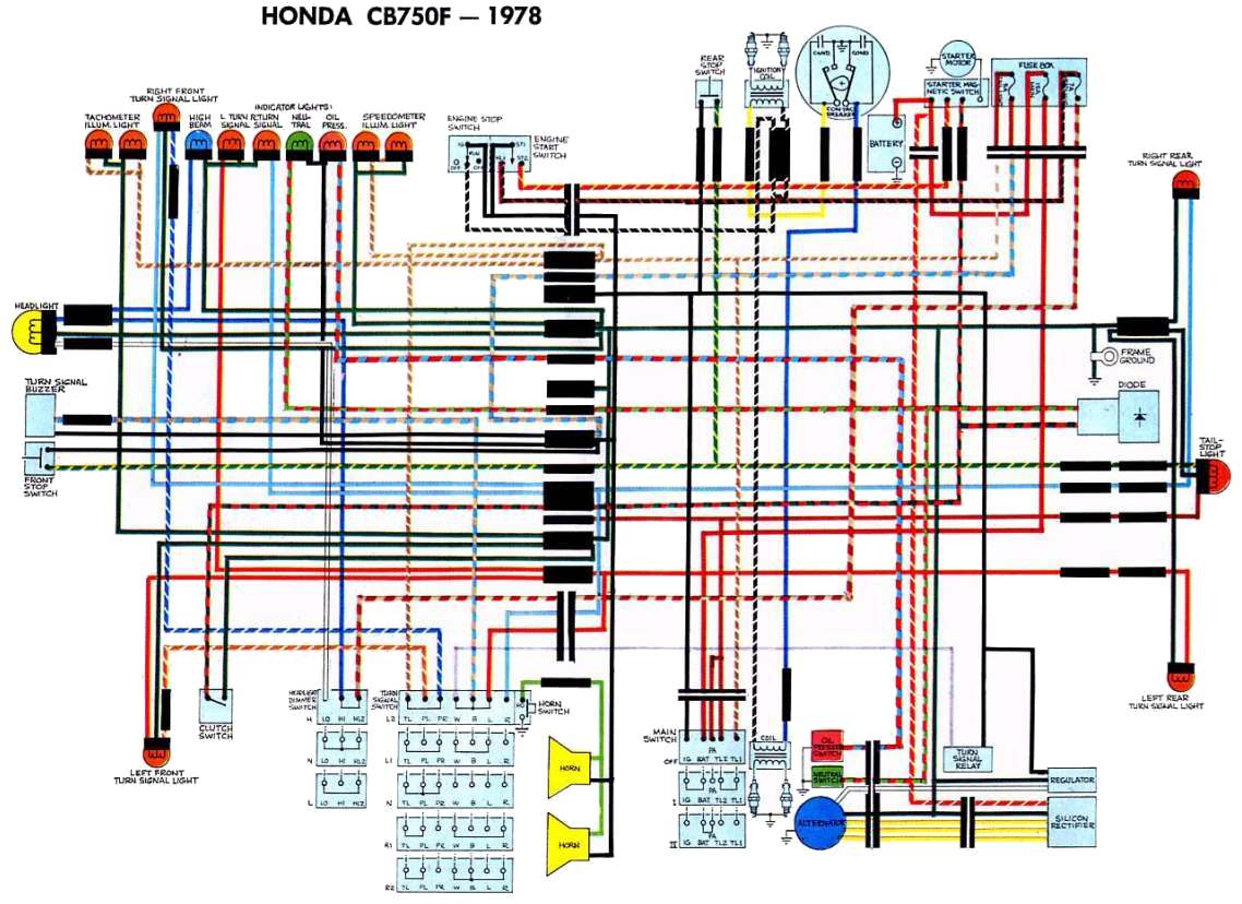
 Title : Kawasaki Motorcycle 1999 Oem Parts Diagram For Ignition Wiring Diagram
Category : Wiring Diagram
Format : PDF
Title : Kawasaki Motorcycle 1999 Oem Parts Diagram For Ignition Wiring Diagram
Category : Wiring Diagram
Format : PDF