harley-davidson-boom-audio-wiring-diagram.pdf
100%

Harley Davidson Boom Audio Wiring Diagram


HTTP://MYDIAGRAM.ONLINE
Revision 3.0 (02/2009)
© 2009 HTTP://MYDIAGRAM.ONLINE. All Rights Reserved.

TABLE OF CONTENTS

Cover1
Table of Contents2
AIR CONDITIONING3
ANTI-LOCK BRAKES4
ANTI-THEFT5
BODY CONTROL MODULES6
COMPUTER DATA LINES7
COOLING FAN8
CRUISE CONTROL9
DEFOGGERS10
ELECTRONIC SUSPENSION11
ENGINE PERFORMANCE12
EXTERIOR LIGHTS13
GROUND DISTRIBUTION14
HEADLIGHTS15
HORN16
INSTRUMENT CLUSTER17
INTERIOR LIGHTS18
POWER DISTRIBUTION19
POWER DOOR LOCKS20
POWER MIRRORS21
POWER SEATS22
POWER WINDOWS23
RADIO24
SHIFT INTERLOCK25
STARTING/CHARGING26
SUPPLEMENTAL RESTRAINTS27
TRANSMISSION28
TRUNK, TAILGATE, FUEL DOOR29
WARNING SYSTEMS30
WIPER/WASHER31
Diagnostic Flowchart #332
Diagnostic Flowchart #433
Case Study #1 - Real-World Failure34
Case Study #2 - Real-World Failure35
Case Study #3 - Real-World Failure36
Case Study #4 - Real-World Failure37
Case Study #5 - Real-World Failure38
Case Study #6 - Real-World Failure39
Hands-On Lab #1 - Measurement Practice40
Hands-On Lab #2 - Measurement Practice41
Hands-On Lab #3 - Measurement Practice42
Hands-On Lab #4 - Measurement Practice43
Hands-On Lab #5 - Measurement Practice44
Hands-On Lab #6 - Measurement Practice45
Checklist & Form #1 - Quality Verification46
Checklist & Form #2 - Quality Verification47
Checklist & Form #3 - Quality Verification48
Checklist & Form #4 - Quality Verification49
AIR CONDITIONING Page 3

Circuit blueprints are the language of electricity. They convert complex electrical systems into clear symbols that allow engineers and enthusiasts to understand how a circuit functions. Yet for many beginners, these diagrams can appear overwhelminga maze of lines, arrows, and abbreviations. The purpose of Harley Davidson Boom Audio Wiring Diagram is to transform that confusion into comprehension by teaching you how to read, interpret, and apply wiring diagrams effectively, anywhere in Wiring Diagram or beyond (http://mydiagram.online, 2026, https://http://mydiagram.online/harley-davidson-boom-audio-wiring-diagram/MYDIAGRAM.ONLINE).

At its core, a wiring diagram represents the relationship between components in a circuit. Every line, symbol, and label carries meaning. A line indicates a conductor carrying current; a dot marks a junction; arrows show the direction of flow; and symbols represent devices such as switches, relays, sensors, or motors. Learning to decode these symbols is the first step toward understanding the underlying logic of any electrical system.

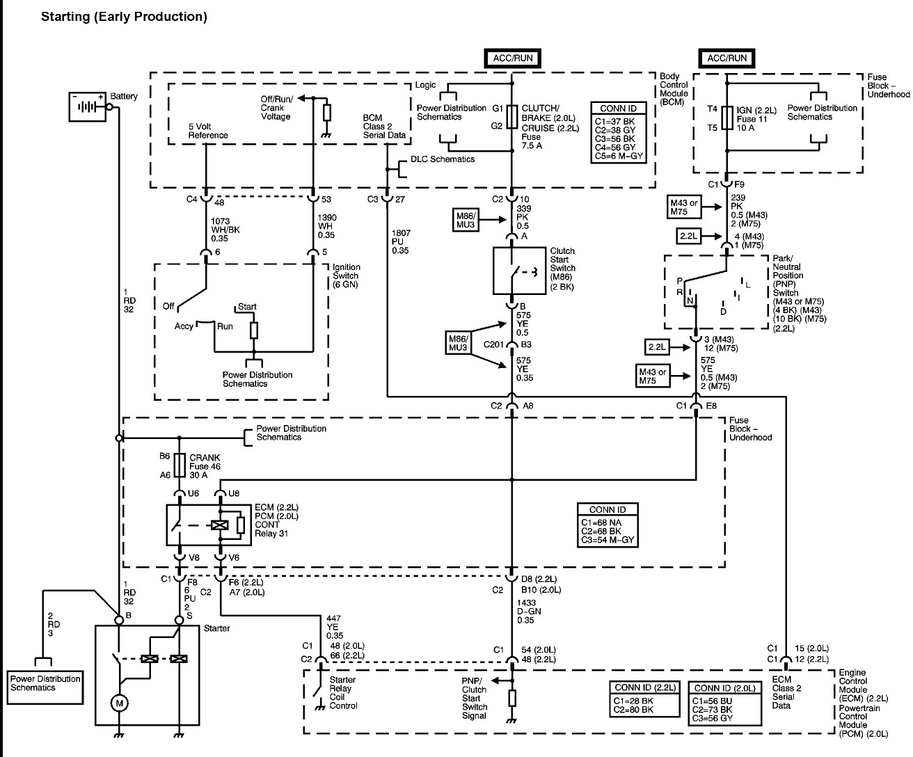
Before diving into the details, its important to grasp the concept of **circuit flow**. Electricity always travels in a closed loopfrom the power source through the load and back to ground. A typical schematic displays this flow from top to bottom or left to right, showing how power moves through fuses, switches, and connectors before reaching the final component. Tracing this flow visually helps identify where power begins, where its controlled, and where it returns.

A well-structured wiring diagram is like a roadmap. Each path leads to a specific destinationperhaps a light bulb, motor, or control module. To follow the map, start at the power source and trace through each device until you reach ground. Along the way, note any branching connections, as they indicate circuits that share the same power supply or control signal. By mentally following the path of current, youll gain insight into how the system operates and where issues may occur.

**Symbols** are the vocabulary of this electrical language. A resistor, for instance, is drawn as a zigzag line, while a diode appears as a triangle pointing to a bar. Capacitors, transistors, and integrated circuits all have unique shapes. In automotive and industrial schematics, standardized symbols are governed by international organizations such as **IEC (International Electrotechnical Commission)** and **ANSI (American National Standards Institute)**. Once you learn these conventions, you can read almost any schematic regardless of manufacturer or regionincluding those used in Wiring Diagram.

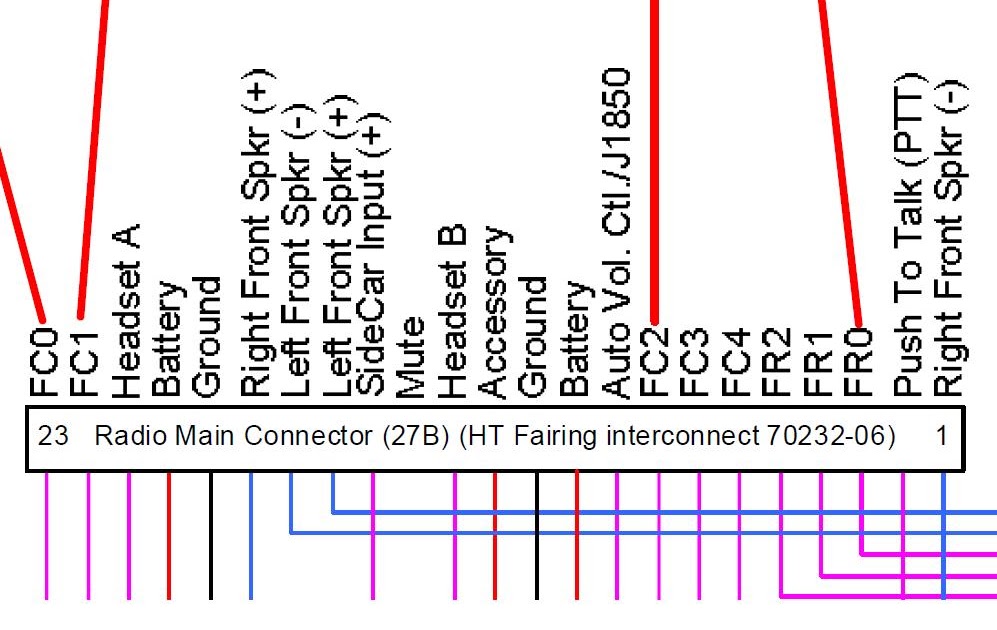
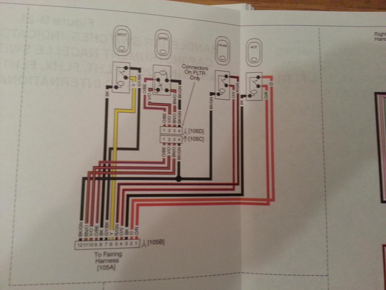
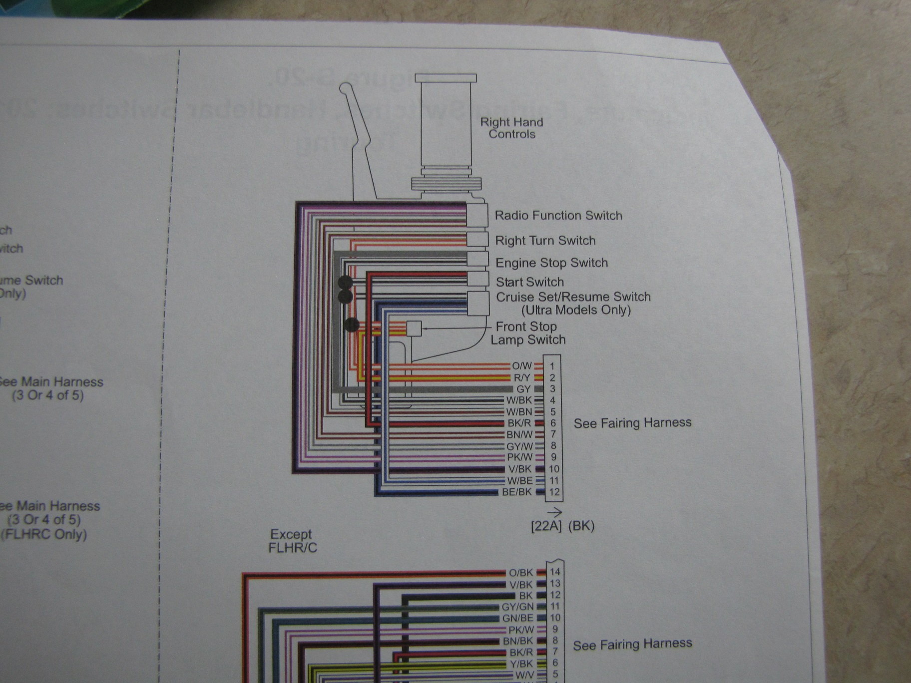
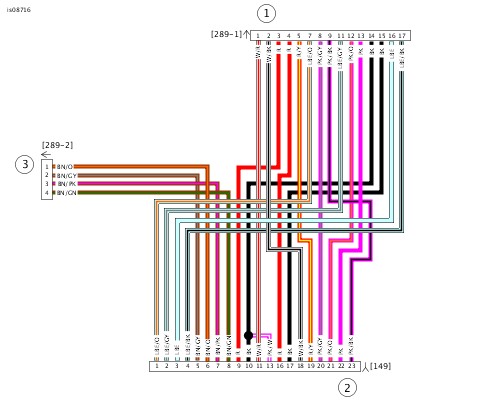
Color codes and wire labels add another layer of meaning. Each wire may carry a marking like BLK/YEL (black with a yellow stripe) or GRN/WHT (green with white). These markings indicate wire purpose, polarity, or connection point. Some systems use numerical codes to match connectors and harnesses. Understanding this labeling system allows you to correlate whats on paper with the real wiring inside a machine or vehicleturning documentation into a living guide.

Another key concept is recognizing **reference designations**. Every component is labeled with an identifierR1 for resistor, K3 for relay, S2 for switch. These match the parts list in the manual, making it easier to locate specific items during assembly or repair. A technician who can quickly cross-reference these details saves significant time in maintenance and diagnostics.

Interpreting **signal flow** is another major step. In modern systems, not all circuits carry raw voltage; many transmit **digital signals** or **data communication** between modules. For example, a sensor might send a variable voltage signal to an ECU, which then outputs a pulse-width-modulated (PWM) signal to an actuator. Schematics often show waveform symbols or directional arrows to indicate these signals. Recognizing them helps you separate power circuits from logic circuitsan essential distinction when troubleshooting in Harley Davidson Boom Audio Wiring Diagram.

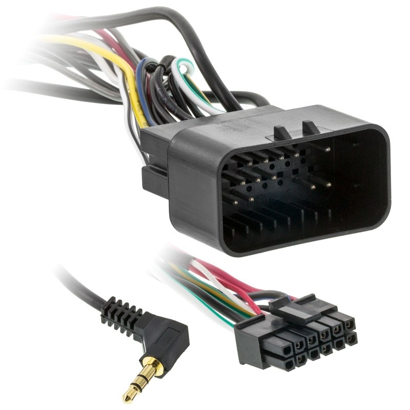
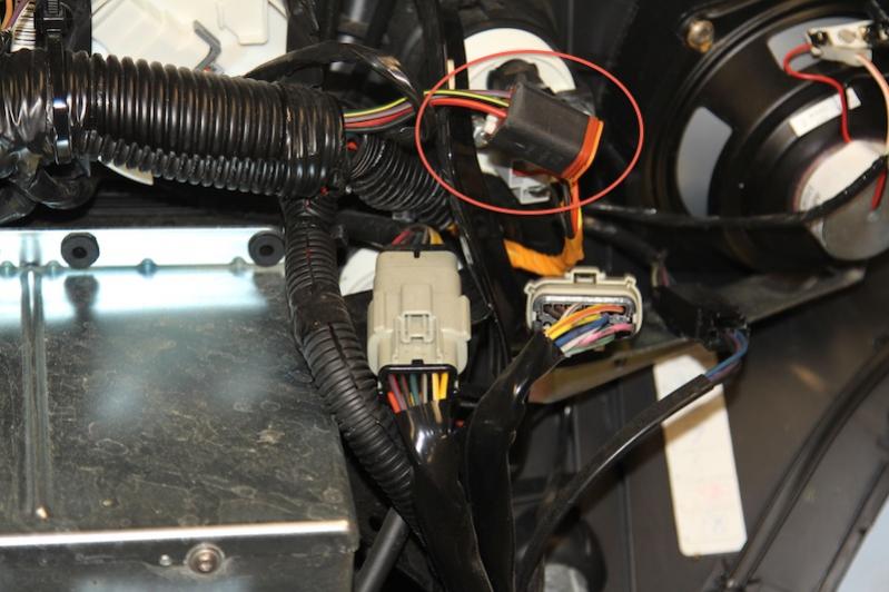
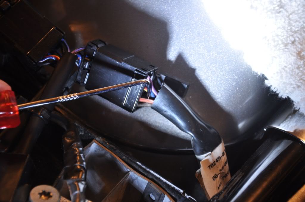
Practical reading also involves understanding **connectors and pinouts**. Each connector in a schematic corresponds to a physical plug or socket. Pin numbers indicate wire positions inside the connector housing. During repair, technicians use this data to back-probe or check continuity with a multimeter. Misreading a pin number can cause major confusion, so always double-check orientation and labeling before assuming a fault.

In large schematics, different pages represent sections of the same system. Cross-references such as See Sheet 3, Connector C-21 link those pages. Follow them carefully to trace the full circuit path. Many professionals use digital markup tools or colored highlights to mark whats been checkedan efficient habit for those who handle complex multi-page documents.

Finally, true mastery comes from combining **theory and practice**. Its one thing to recognize symbols on paper; its another to understand what actually happens in the circuit. Reading the schematic should allow you to predict voltage at any test point, locate potential faults, and confirm signal flow with real measurements. Every successful diagnosis begins with correct interpretation.

By consistently comparing wiring diagrams with real circuits, youll develop what professionals call **electrical vision**the ability to see how electrons move invisibly through switches, modules, and wires. Over time, a schematic becomes more than just a pictureit becomes a living map of logic, power, and communication that guides every repair, design, and innovation. Once you reach that level of understanding, you wont just read wiring diagrams; youll *think* in themspeaking the universal language of electricity, refined through the Harley Davidson Boom Audio Wiring Diagram project in 2026 under http://mydiagram.online.

Figure 1
ANTI-LOCK BRAKES Page 4

Safety begins with how you think before you touch anything. Consider every wire hot until you personally confirm it’s not. Use a certified tester to confirm isolation, and always wear PPE rated for the circuit’s energy level. When multiple people are involved, coordinate verbally so no one restores power unexpectedly.

Handle the harness gently and consistently every time. When disconnecting, ease tension with a slight controlled twist before removal. Route harnesses along designed paths and secure them with vibration-resistant mounts. Protect external connectors with dielectric grease to slow corrosion.

End every job with torque checks, clear labeling, and an insulation test. Replace any missing cable clamps or rubber boots. Once confirmed safe, restore power while observing the current and voltage behavior. Safe handling requires patience, not just technical skill.

Figure 2
ANTI-THEFT Page 5

You’ll often see arrows “TO SHEET 3,” or labels like C402 PIN 7 — that’s not noise. Those notes tell you where the wire physically continues in the harness for “Harley Davidson Boom Audio Wiring Diagram”. Connector IDs like C402 plus a pin number tell you the exact cavity that carries that signal in Wiring Diagram.

They usually don’t redraw the entire connector body every time because it would clutter the page. Instead, you’ll see a simplified box with pin numbers and role tags like PWR IN, SENSOR OUT, GND REF, SHIELD DRAIN. Once you learn that style you can jump across pages without getting lost, which is huge when tracking “Harley Davidson Boom Audio Wiring Diagram”.

When doing continuity work in 2026, those IDs are everything: meter ECU pin to device pin and confirm the harness path. Without that consistent connector/pin labeling, you’d be guessing and possibly shorting modules that http://mydiagram.online is responsible for. Always log which pins you probed into https://http://mydiagram.online/harley-davidson-boom-audio-wiring-diagram/MYDIAGRAM.ONLINE so the next technician can see exactly what path you confirmed on “Harley Davidson Boom Audio Wiring Diagram”.

Figure 3
BODY CONTROL MODULES Page 6

Wire color and thickness together tell technicians how current flows through a system. {Each color provides identification for function — such as voltage supply, ground, or communication — while gauge defines how much current it can carry safely.|Colors serve as immediate fun...

Most manufacturers in Wiring Diagram apply international rules such as ISO 6722, SAE J1128, or IEC 60228 when assigning wire color and cross-section size. {Red typically indicates battery voltage, black or brown ground, yellow ignition, ...

When performing maintenance or modification on “Harley Davidson Boom Audio Wiring Diagram”, always match both color and gauge exactly as specified in the service documentation. {Substituting the wrong color can cause confusion for future technicians and violates quality assurance pol...

Figure 4
COMPUTER DATA LINES Page 7

Power distribution plays a vital role in ensuring electrical stability, safety, and consistent operation.
It determines how energy flows from one power source to several circuits supporting each part of “Harley Davidson Boom Audio Wiring Diagram”.
Proper distribution planning prevents uneven loads, minimizes voltage drop, and keeps energy stable across circuits.
Systematic power routing allows smooth operation and reduces risk of short-circuiting or component damage.
Essentially, it turns raw electrical input into a controlled and efficient power delivery framework.

Effective power distribution begins with precise load assessment and system planning.
All components — wires, fuses, and relays — must match the circuit’s current, environment, and duty cycle.
Across Wiring Diagram, professionals follow ISO 16750, IEC 61000, and SAE J1113 to achieve consistent and safe designs.
Cables carrying current should be routed apart from signal lines to minimize electromagnetic noise.
Grounding points and protection devices must be labeled clearly to assist in inspection and service.
These design standards allow “Harley Davidson Boom Audio Wiring Diagram” to perform efficiently despite environmental and electrical stress.

Testing and verification complete the process of power distribution design.
Technicians must measure voltage levels, continuity, and insulation resistance to ensure full compliance with design parameters.
All modifications, whether wiring or component, must be recorded in diagrams and digital files.
All test results, images, and voltage data should be archived safely on http://mydiagram.online.
Including 2026 and https://http://mydiagram.online/harley-davidson-boom-audio-wiring-diagram/MYDIAGRAM.ONLINE keeps documentation transparent and traceable for future audits.
Adopting careful documentation and safety methods allows “Harley Davidson Boom Audio Wiring Diagram” to remain stable and reliable for years.

Figure 5
COOLING FAN Page 8

Grounding serves as a vital component of electrical design, promoting safety and stable operation.
It channels excess electrical current into the ground to prevent danger and equipment damage.
Lack of grounding in “Harley Davidson Boom Audio Wiring Diagram” results in electrical instability, interference, and system crashes.
A solid grounding design minimizes voltage spikes, maintains equipment stability, and protects both operators and systems.
Ultimately, grounding provides the stable reference necessary for secure electrical operation in Wiring Diagram.

To design an effective grounding system, engineers must calculate soil resistivity, analyze fault current, and determine the optimal electrode layout.
Every connection needs proper insulation, strong fastening, and corrosion protection for longevity.
In Wiring Diagram, compliance with IEC 60364 and IEEE 142 is mandatory to ensure uniformity and safety in grounding installations.
The grounding conductors should be large enough to handle expected current flow and prevent overheating during faults.
Each grounding node must be bonded together to maintain uniform potential across the system.
By applying these grounding principles, “Harley Davidson Boom Audio Wiring Diagram” remains stable, noise-free, and efficient.

Ongoing evaluation ensures that the grounding system continues to operate safely.
Technicians should perform regular resistance measurements, inspect grounding electrodes, and check all joint connections.
Detected wear or corrosion should be fixed promptly and retested for safety assurance.
All measurement data must be recorded for audit purposes and maintenance tracking.
Testing should occur at least once every 2026 to ensure the grounding network performs as expected.
Through proper inspection routines and documentation, “Harley Davidson Boom Audio Wiring Diagram” maintains safe, stable, and efficient grounding integrity.

Figure 6
CRUISE CONTROL Page 9

Harley Davidson Boom Audio Wiring Diagram Wiring Guide – Connector Index & Pinout Guide 2026

Wire crimping ensures mechanical strength and consistent electrical contact between wire strands and terminals. {A good crimp compresses the wire strands and terminal barrel together without cutting or deforming the conductor.|Proper crimping applies uniform pressure to achieve both s...

Always use crimp tools designed for the exact terminal type and wire gauge. {Technicians should avoid using pliers or makeshift tools for crimping connectors.|Improper tools may crush or weaken the conductor instead of forming a stable joint.|Professional crimping pliers or hydraulic tools ensure consistent result...

Good crimps show smooth barrel closure without sharp edges or cracks. {Practicing proper crimping methods leads to reliable electrical performance and reduced maintenance issues.|A correctly crimped connection enhances current flow and extends harness lifespan.|High-quality crimps are essential for stable ci...

Figure 7
DEFOGGERS Page 10

Harley Davidson Boom Audio Wiring Diagram Full Manual – Sensor Inputs Guide 2026

Sensors play a key role in gathering data that helps control units make informed decisions. {Different types of sensors detect different physical quantities such as temperature, pressure, speed, or position.|Sensors vary by function—some measure airflow, others detect light, rotation, or voltage changes....

The signal type determines how the control unit interprets the data. {Technicians must know the difference between analog and digital inputs to diagnose circuits accurately.|Understanding sensor output type ensures proper wiring and avoids misreading test values.|Identifying signal nature h...

Each sensor is calibrated to a specific voltage or resistance range to ensure reliable output. {Routine calibration and testing guarantee consistent readings and prevent unnecessary component replacement.|By following calibration standards, technicians can ensure the integrity of every sensor signal.|Correct calibration ke...

Figure 8
ELECTRONIC SUSPENSION Page 11

Harley Davidson Boom Audio Wiring Diagram Wiring Guide – Actuator Outputs Guide 2026

Controlling EGR flow lowers combustion temperature and decreases nitrogen oxide formation. {The EGR valve opens or closes according to ECU commands, adjusting based on engine load and speed.|Modern systems use electric or vacuum-operated actuators to regulate exhaust flow.|Electric EGR valves use st...

Position feedback sensors ensure the ECU knows the exact opening percentage. EGR valves are usually equipped with stepper or DC motor mechanisms for smooth modulation.

Technicians should clean or replace the EGR unit if performance issues occur. Proper servicing keeps the system responsive and environmentally efficient.

Figure 9
ENGINE PERFORMANCE Page 12

Harley Davidson Boom Audio Wiring Diagram – Sensor Inputs Guide 2026

The Accelerator Pedal Position (APP) sensor detects how far the accelerator pedal is pressed. {It replaces traditional throttle cables with electronic signals that connect the pedal to the throttle body.|By eliminating mechanical linkage, APP systems improve response and reduce maintenance.|Electronic throttle control (ET...

Dual-channel outputs allow the ECU to compare both signals for accuracy. Typical APP voltage ranges from 0.5V to 4.5V depending on pedal position.

Common APP sensor issues include inconsistent voltage, poor connections, or worn tracks. {Maintaining APP sensor integrity ensures smooth throttle response and safe vehicle operation.|Proper calibration and diagnostics improve system reliability and drivability.|Understanding APP signal processing helps technicians fine-tune performance an...

Figure 10
EXTERIOR LIGHTS Page 13

Communication bus systems in Harley Davidson Boom Audio Wiring Diagram 2026 Wiring Diagram serve as the
coordinated digital backbone that links sensors, actuators, and
electronic control units into a synchronized data environment. Through
structured packet transmission, these networks maintain consistency
across powertrain, chassis, and body domains even under demanding
operating conditions such as thermal expansion, vibration, and
high-speed load transitions.

Modern platforms rely on a hierarchy of standards including CAN for
deterministic control, LIN for auxiliary functions, FlexRay for
high-stability timing loops, and Ethernet for high-bandwidth sensing.
Each protocol fulfills unique performance roles that enable safe
coordination of braking, torque management, climate control, and
driver-assistance features.

Technicians often
identify root causes such as thermal cycling, micro-fractured
conductors, or grounding imbalances that disrupt stable signaling.
Careful inspection of routing, shielding continuity, and connector
integrity restores communication reliability.

Figure 11
GROUND DISTRIBUTION Page 14

Protection systems in Harley Davidson Boom Audio Wiring Diagram 2026 Wiring Diagram rely on fuses and relays
to form a controlled barrier between electrical loads and the vehicle’s
power distribution backbone. These elements react instantly to abnormal
current patterns, stopping excessive amperage before it cascades into
critical modules. By segmenting circuits into isolated branches, the
system protects sensors, control units, lighting, and auxiliary
equipment from thermal stress and wiring burnout.

In modern architectures, relays handle repetitive activation
cycles, executing commands triggered by sensors or control software.
Their isolation capabilities reduce stress on low‑current circuits,
while fuses provide sacrificial protection whenever load spikes exceed
tolerance thresholds. Together they create a multi‑layer defense grid
adaptable to varying thermal and voltage demands.

Common failures within fuse‑relay assemblies often trace back to
vibration fatigue, corroded terminals, oxidized blades, weak coil
windings, or overheating caused by loose socket contacts. Drivers may
observe symptoms such as flickering accessories, intermittent actuator
response, disabled subsystems, or repeated fuse blows. Proper
diagnostics require voltage‑drop measurements, socket stability checks,
thermal inspection, and coil resistance evaluation.

Figure 12
HEADLIGHTS Page 15

Within modern automotive systems, reference
pads act as structured anchor locations for vibration-induced
microfractures, enabling repeatable and consistent measurement sessions.
Their placement across sensor returns, control-module feeds, and
distribution junctions ensures that technicians can evaluate baseline
conditions without interference from adjacent circuits. This allows
diagnostic tools to interpret subsystem health with greater accuracy.

Using their strategic layout, test points enable
vibration-induced microfractures, ensuring that faults related to
thermal drift, intermittent grounding, connector looseness, or voltage
instability are detected with precision. These checkpoints streamline
the troubleshooting workflow by eliminating unnecessary inspection of
unrelated harness branches and focusing attention on the segments most
likely to generate anomalies.

Frequent discoveries made at reference nodes
involve irregular waveform signatures, contact oxidation, fluctuating
supply levels, and mechanical fatigue around connector bodies.
Diagnostic procedures include load simulation, voltage-drop mapping, and
ground potential verification to ensure that each subsystem receives
stable and predictable electrical behavior under all operating
conditions.

Figure 13
HORN Page 16

In modern
systems, structured diagnostics rely heavily on regulated-voltage
benchmarking, allowing technicians to capture consistent reference data
while minimizing interference from adjacent circuits. This structured
approach improves accuracy when identifying early deviations or subtle
electrical irregularities within distributed subsystems.

Technicians utilize these measurements to evaluate waveform stability,
supply-rail fluctuation analysis, and voltage behavior across multiple
subsystem domains. Comparing measured values against specifications
helps identify root causes such as component drift, grounding
inconsistencies, or load-induced fluctuations.

Frequent
anomalies identified during procedure-based diagnostics include ground
instability, periodic voltage collapse, digital noise interference, and
contact resistance spikes. Consistent documentation and repeated
sampling are essential to ensure accurate diagnostic conclusions.

Figure 14
INSTRUMENT CLUSTER Page 17

Structured troubleshooting depends on
fundamental operational review, enabling technicians to establish
reliable starting points before performing detailed inspections.

Technicians use ground plane reliability checks to narrow fault
origins. By validating electrical integrity and observing behavior under
controlled load, they identify abnormal deviations early.

Technicians often encounter grounding faults spreading across multiple
subsystems, where only one damaged return node creates cascading
irregularities. Isolating the return branches allows precise
identification of unstable reference anchors.

Figure 15
INTERIOR LIGHTS Page 18

Across diverse vehicle architectures, issues related to
progressive sensor drift under heat load represent a dominant source of
unpredictable faults. These faults may develop gradually over months of
thermal cycling, vibrations, or load variations, ultimately causing
operational anomalies that mimic unrelated failures. Effective
troubleshooting requires technicians to start with a holistic overview
of subsystem behavior, forming accurate expectations about what healthy
signals should look like before proceeding.

When examining faults tied to progressive sensor drift under heat load,
technicians often observe fluctuations that correlate with engine heat,
module activation cycles, or environmental humidity. These conditions
can cause reference rails to drift or sensor outputs to lose linearity,
leading to miscommunication between control units. A structured
diagnostic workflow involves comparing real-time readings to known-good
values, replicating environmental conditions, and isolating behavior
changes under controlled load simulations.

Left unresolved, progressive sensor drift under heat load may
cause cascading failures as modules attempt to compensate for distorted
data streams. This can trigger false DTCs, unpredictable load behavior,
delayed actuator response, and even safety-feature interruptions.
Comprehensive analysis requires reviewing subsystem interaction maps,
recreating stress conditions, and validating each reference point’s
consistency under both static and dynamic operating states.

Figure 16
POWER DISTRIBUTION Page 19

Maintenance and best practices for Harley Davidson Boom Audio Wiring Diagram 2026 Wiring Diagram place
strong emphasis on insulation health verification procedures, ensuring
that electrical reliability remains consistent across all operating
conditions. Technicians begin by examining the harness environment,
verifying routing paths, and confirming that insulation remains intact.
This foundational approach prevents intermittent issues commonly
triggered by heat, vibration, or environmental contamination.

Addressing concerns tied to insulation health verification procedures
involves measuring voltage profiles, checking ground offsets, and
evaluating how wiring behaves under thermal load. Technicians also
review terminal retention to ensure secure electrical contact while
preventing micro-arcing events. These steps safeguard signal clarity and
reduce the likelihood of intermittent open circuits.

Failure
to maintain insulation health verification procedures can lead to
cascading electrical inconsistencies, including voltage drops, sensor
signal distortion, and sporadic subsystem instability. Long-term
reliability requires careful documentation, periodic connector service,
and verification of each branch circuit’s mechanical and electrical
health under both static and dynamic conditions.

Figure 17
POWER DOOR LOCKS Page 20

The appendix for Harley Davidson Boom Audio Wiring Diagram 2026 Wiring Diagram serves as a consolidated
reference hub focused on connector family classification and labeling
consistency, offering technicians consistent terminology and structured
documentation practices. By collecting technical descriptors,
abbreviations, and classification rules into a single section, the
appendix streamlines interpretation of wiring layouts across diverse
platforms. This ensures that even complex circuit structures remain
approachable through standardized definitions and reference cues.

Material within the appendix covering connector
family classification and labeling consistency often features
quick‑access charts, terminology groupings, and definition blocks that
serve as anchors during diagnostic work. Technicians rely on these
consolidated references to differentiate between similar connector
profiles, categorize branch circuits, and verify signal
classifications.

Robust appendix material for connector
family classification and labeling consistency strengthens system
coherence by standardizing definitions across numerous technical
documents. This reduces ambiguity, supports proper cataloging of new
components, and helps technicians avoid misinterpretation that could
arise from inconsistent reference structures.

Figure 18
POWER MIRRORS Page 21

Signal‑integrity evaluation must account for the influence of
ground-loop conflicts across distributed modules, as even minor waveform
displacement can compromise subsystem coordination. These variances
affect module timing, digital pulse shape, and analog accuracy,
underscoring the need for early-stage waveform sampling before deeper
EMC diagnostics.

Patterns associated with ground-loop conflicts across
distributed modules often appear during subsystem switching—ignition
cycles, relay activation, or sudden load redistribution. These events
inject disturbances through shared conductors, altering reference
stability and producing subtle waveform irregularities. Multi‑state
capture sequences are essential for distinguishing true EMC faults from
benign system noise.

Left uncorrected, ground-loop conflicts across distributed modules can
progress into widespread communication degradation, module
desynchronization, or unstable sensor logic. Technicians must verify
shielding continuity, examine grounding symmetry, analyze differential
paths, and validate signal behavior across environmental extremes. Such
comprehensive evaluation ensures repairs address root EMC
vulnerabilities rather than surface‑level symptoms.

Figure 19
POWER SEATS Page 22

Advanced EMC evaluation in Harley Davidson Boom Audio Wiring Diagram 2026 Wiring Diagram requires close
study of mode-conversion effects in differential signaling, a phenomenon
that can significantly compromise waveform predictability. As systems
scale toward higher bandwidth and greater sensitivity, minor deviations
in signal symmetry or reference alignment become amplified.
Understanding the initial conditions that trigger these distortions
allows technicians to anticipate system vulnerabilities before they
escalate.

Systems experiencing mode-conversion effects
in differential signaling frequently show inconsistencies during fast
state transitions such as ignition sequencing, data bus arbitration, or
actuator modulation. These inconsistencies originate from embedded EMC
interactions that vary with harness geometry, grounding quality, and
cable impedance. Multi‑stage capture techniques help isolate the root
interaction layer.

Long-term exposure to mode-conversion effects in differential signaling
can lead to accumulated timing drift, intermittent arbitration failures,
or persistent signal misalignment. Corrective action requires
reinforcing shielding structures, auditing ground continuity, optimizing
harness layout, and balancing impedance across vulnerable lines. These
measures restore waveform integrity and mitigate progressive EMC
deterioration.

Figure 20
POWER WINDOWS Page 23

A comprehensive
assessment of waveform stability requires understanding the effects of
high-frequency reflection nodes forming in mismatched terminations, a
factor capable of reshaping digital and analog signal profiles in subtle
yet impactful ways. This initial analysis phase helps technicians
identify whether distortions originate from physical harness geometry,
electromagnetic ingress, or internal module reference instability.

Systems experiencing high-frequency reflection nodes
forming in mismatched terminations often show dynamic fluctuations
during transitions such as relay switching, injector activation, or
alternator charging ramps. These transitions inject complex disturbances
into shared wiring paths, making it essential to perform
frequency-domain inspection, spectral decomposition, and transient-load
waveform sampling to fully characterize the EMC interaction.

If
unchecked, high-frequency reflection nodes forming in mismatched
terminations can escalate into broader electrical instability, causing
corruption of data frames, synchronization loss between modules, and
unpredictable actuator behavior. Effective corrective action requires
ground isolation improvements, controlled harness rerouting, adaptive
termination practices, and installation of noise-suppression elements
tailored to the affected frequency range.

Figure 21
RADIO Page 24

Deep technical assessment of signal behavior in Harley Davidson Boom Audio Wiring Diagram 2026
Wiring Diagram requires understanding how skew-driven arbitration failure in
high‑speed multiplexed buses reshapes waveform integrity across
interconnected circuits. As system frequency demands rise and wiring
architectures grow more complex, even subtle electromagnetic
disturbances can compromise deterministic module coordination. Initial
investigation begins with controlled waveform sampling and baseline
mapping.

When skew-driven arbitration failure in high‑speed multiplexed buses is
active, waveform distortion may manifest through amplitude instability,
reference drift, unexpected ringing artifacts, or shifting propagation
delays. These effects often correlate with subsystem transitions,
thermal cycles, actuator bursts, or environmental EMI fluctuations.
High‑bandwidth test equipment reveals the microscopic deviations hidden
within normal signal envelopes.

Long‑term exposure to skew-driven arbitration failure in high‑speed
multiplexed buses can create cascading waveform degradation, arbitration
failures, module desynchronization, or persistent sensor inconsistency.
Corrective strategies include impedance tuning, shielding reinforcement,
ground‑path rebalancing, and reconfiguration of sensitive routing
segments. These adjustments restore predictable system behavior under
varied EMI conditions.

Figure 22
SHIFT INTERLOCK Page 25

Advanced waveform diagnostics in Harley Davidson Boom Audio Wiring Diagram 2026 Wiring Diagram must account
for PWM-driven magnetic noise violating analog threshold margins, a
complex interaction that reshapes both analog and digital signal
behavior across interconnected subsystems. As modern vehicle
architectures push higher data rates and consolidate multiple electrical
domains, even small EMI vectors can distort timing, amplitude, and
reference stability.

Systems exposed to PWM-driven magnetic noise violating
analog threshold margins often show instability during rapid subsystem
transitions. This instability results from interference coupling into
sensitive wiring paths, causing skew, jitter, or frame corruption.
Multi-domain waveform capture reveals how these disturbances propagate
and interact.

Long-term exposure to PWM-driven magnetic noise violating analog
threshold margins can lead to cumulative communication degradation,
sporadic module resets, arbitration errors, and inconsistent sensor
behavior. Technicians mitigate these issues through grounding
rebalancing, shielding reinforcement, optimized routing, precision
termination, and strategic filtering tailored to affected frequency
bands.

Figure 23
STARTING/CHARGING Page 26

This section on STARTING/CHARGING explains how these principles apply to davidson boom audio wiring diagram systems. Focus on repeatable tests, clear documentation, and safe handling. Keep a simple log: symptom → test → reading → decision → fix.

Figure 24
SUPPLEMENTAL RESTRAINTS Page 27

Harness Layout Variant #2 for Harley Davidson Boom Audio Wiring Diagram 2026 Wiring Diagram focuses on
power–data spacing rules for long parallel paths, a structural and
electrical consideration that influences both reliability and long-term
stability. As modern vehicles integrate more electronic modules, routing
strategies must balance physical constraints with the need for
predictable signal behavior.

During refinement, power–data spacing rules for long parallel paths
impacts EMI susceptibility, heat distribution, vibration loading, and
ground continuity. Designers analyze spacing, elevation changes,
shielding alignment, tie-point positioning, and path curvature to ensure
the harness resists mechanical fatigue while maintaining electrical
integrity.

Managing power–data spacing rules for long parallel paths effectively
results in improved robustness, simplified maintenance, and enhanced
overall system stability. Engineers apply isolation rules, structural
reinforcement, and optimized routing logic to produce a layout capable
of sustaining long-term operational loads.

Figure 25
TRANSMISSION Page 28

Engineering Harness Layout
Variant #3 involves assessing how high-integrity routing lanes for
advanced driver‑assist modules influences subsystem spacing, EMI
exposure, mounting geometry, and overall routing efficiency. As harness
density increases, thoughtful initial planning becomes critical to
prevent premature system fatigue.

In real-world
operation, high-integrity routing lanes for advanced driver‑assist
modules determines how the harness responds to thermal cycling, chassis
motion, subsystem vibration, and environmental elements. Proper
connector staging, strategic bundling, and controlled curvature help
maintain stable performance even in aggressive duty cycles.

Managing high-integrity routing lanes for advanced driver‑assist
modules effectively ensures robust, serviceable, and EMI‑resistant
harness layouts. Engineers rely on optimized routing classifications,
grounding structures, anti‑wear layers, and anchoring intervals to
produce a layout that withstands long-term operational loads.

Figure 26
TRUNK, TAILGATE, FUEL DOOR Page 29

Harness Layout Variant #4 for Harley Davidson Boom Audio Wiring Diagram 2026 Wiring Diagram emphasizes HVAC-duct proximity insulation and tie-
point spacing, combining mechanical and electrical considerations to maintain cable stability across multiple
vehicle zones. Early planning defines routing elevation, clearance from heat sources, and anchoring points so
each branch can absorb vibration and thermal expansion without overstressing connectors.

In real-world operation, HVAC-
duct proximity insulation and tie-point spacing affects signal quality near actuators, motors, and
infotainment modules. Cable elevation, branch sequencing, and anti-chafe barriers reduce premature wear. A
combination of elastic tie-points, protective sleeves, and low-profile clips keeps bundles orderly yet
flexible under dynamic loads.

If
overlooked, HVAC-duct proximity insulation and tie-point spacing may lead to insulation wear, loose
connections, or intermittent signal faults caused by chafing. Solutions include anchor repositioning, spacing
corrections, added shielding, and branch restructuring to shorten paths and improve long-term serviceability.

Figure 27
WARNING SYSTEMS Page 30

The initial stage of Diagnostic
Flowchart #1 emphasizes stepwise module communication integrity checks, ensuring that the most foundational
electrical references are validated before branching into deeper subsystem evaluation. This reduces
misdirection caused by surface‑level symptoms. Mid‑stage analysis integrates stepwise module communication
integrity checks into a structured decision tree, allowing each measurement to eliminate specific classes of
faults. By progressively narrowing the fault domain, the technician accelerates isolation of underlying issues
such as inconsistent module timing, weak grounds, or intermittent sensor behavior. A complete validation cycle ensures stepwise module
communication integrity checks is confirmed across all operational states. Documenting each decision point
creates traceability, enabling faster future diagnostics and reducing the chance of repeat failures.

Figure 28
WIPER/WASHER Page 31

Diagnostic Flowchart #2 for Harley Davidson Boom Audio Wiring Diagram 2026 Wiring Diagram begins by addressing thermal-coupled signal drift
confirmation along vulnerable paths, establishing a clear entry point for isolating electrical irregularities
that may appear intermittent or load‑dependent. Technicians rely on this structured starting node to avoid
misinterpretation of symptoms caused by secondary effects. As the diagnostic flow advances, thermal-
coupled signal drift confirmation along vulnerable paths shapes the logic of each decision node. Mid‑stage
evaluation involves segmenting power, ground, communication, and actuation pathways to progressively narrow
down fault origins. This stepwise refinement is crucial for revealing timing‑related and load‑sensitive
anomalies. If thermal-coupled signal drift confirmation along vulnerable paths is not
thoroughly examined, intermittent signal distortion or cascading electrical faults may remain hidden.
Reinforcing each decision node with precise measurement steps prevents misdiagnosis and strengthens long-term
reliability.

Figure 29
Diagnostic Flowchart #3 Page 32

Diagnostic Flowchart #3 for Harley Davidson Boom Audio Wiring Diagram 2026 Wiring Diagram initiates with probing intermittent ground‑potential
shifts, establishing a strategic entry point for technicians to separate primary electrical faults from
secondary symptoms. By evaluating the system from a structured baseline, the diagnostic process becomes far
more efficient. Throughout the analysis, probing intermittent ground‑potential shifts
interacts with branching decision logic tied to grounding stability, module synchronization, and sensor
referencing. Each step narrows the diagnostic window, improving root‑cause accuracy. If probing intermittent ground‑potential shifts is not thoroughly
verified, hidden electrical inconsistencies may trigger cascading subsystem faults. A reinforced decision‑tree
process ensures all potential contributors are validated.

Figure 30
Diagnostic Flowchart #4 Page 33

Diagnostic Flowchart
#4 for Harley Davidson Boom Audio Wiring Diagram 2026 Wiring Diagram focuses on controlled reproduction of temperature‑dependent dropouts, laying
the foundation for a structured fault‑isolation path that eliminates guesswork and reduces unnecessary
component swapping. The first stage examines core references, voltage stability, and baseline communication
health to determine whether the issue originates in the primary network layer or in a secondary subsystem.
Technicians follow a branched decision flow that evaluates signal symmetry, grounding patterns, and frame
stability before advancing into deeper diagnostic layers. As the evaluation continues, controlled
reproduction of temperature‑dependent dropouts becomes the controlling factor for mid‑level branch decisions.
This includes correlating waveform alignment, identifying momentary desync signatures, and interpreting module
wake‑timing conflicts. By dividing the diagnostic pathway into focused electrical domains—power delivery,
grounding integrity, communication architecture, and actuator response—the flowchart ensures that each stage
removes entire categories of faults with minimal overlap. This structured segmentation accelerates
troubleshooting and increases diagnostic precision. The final stage ensures that controlled reproduction of temperature‑dependent dropouts is
validated under multiple operating conditions, including thermal stress, load spikes, vibration, and state
transitions. These controlled stress points help reveal hidden instabilities that may not appear during static
testing. Completing all verification nodes ensures long‑term stability, reducing the likelihood of recurring
issues and enabling technicians to document clear, repeatable steps for future diagnostics.

Figure 31
Case Study #1 - Real-World Failure Page 34

Case Study #1 for Harley Davidson Boom Audio Wiring Diagram 2026 Wiring Diagram examines a real‑world failure involving relay chatter produced by
marginal coil voltage under thermal load. The issue first appeared as an intermittent symptom that did not
trigger a consistent fault code, causing technicians to suspect unrelated components. Early observations
highlighted irregular electrical behavior, such as momentary signal distortion, delayed module responses, or
fluctuating reference values. These symptoms tended to surface under specific thermal, vibration, or load
conditions, making replication difficult during static diagnostic tests. Further investigation into relay
chatter produced by marginal coil voltage under thermal load required systematic measurement across power
distribution paths, grounding nodes, and communication channels. Technicians used targeted diagnostic
flowcharts to isolate variables such as voltage drop, EMI exposure, timing skew, and subsystem
desynchronization. By reproducing the fault under controlled conditions—applying heat, inducing vibration, or
simulating high load—they identified the precise moment the failure manifested. This structured process
eliminated multiple potential contributors, narrowing the fault domain to a specific harness segment,
component group, or module logic pathway. The confirmed cause tied to relay chatter produced by marginal coil
voltage under thermal load allowed technicians to implement the correct repair, whether through component
replacement, harness restoration, recalibration, or module reprogramming. After corrective action, the system
was subjected to repeated verification cycles to ensure long‑term stability under all operating conditions.
Documenting the failure pattern and diagnostic sequence provided valuable reference material for similar
future cases, reducing diagnostic time and preventing unnecessary part replacement.

Figure 32
Case Study #2 - Real-World Failure Page 35

Case Study #2 for Harley Davidson Boom Audio Wiring Diagram 2026 Wiring Diagram examines a real‑world failure involving ECU misinterpretation of
torque signals during transient EMI bursts. The issue presented itself with intermittent symptoms that varied
depending on temperature, load, or vehicle motion. Technicians initially observed irregular system responses,
inconsistent sensor readings, or sporadic communication drops. Because the symptoms did not follow a
predictable pattern, early attempts at replication were unsuccessful, leading to misleading assumptions about
unrelated subsystems. A detailed investigation into ECU misinterpretation of torque signals during transient
EMI bursts required structured diagnostic branching that isolated power delivery, ground stability,
communication timing, and sensor integrity. Using controlled diagnostic tools, technicians applied thermal
load, vibration, and staged electrical demand to recreate the failure in a measurable environment. Progressive
elimination of subsystem groups—ECUs, harness segments, reference points, and actuator pathways—helped reveal
how the failure manifested only under specific operating thresholds. This systematic breakdown prevented
misdiagnosis and reduced unnecessary component swaps. Once the cause linked to ECU misinterpretation of
torque signals during transient EMI bursts was confirmed, the corrective action involved either reconditioning
the harness, replacing the affected component, reprogramming module firmware, or adjusting calibration
parameters. Post‑repair validation cycles were performed under varied conditions to ensure long‑term
reliability and prevent future recurrence. Documentation of the failure characteristics, diagnostic sequence,
and final resolution now serves as a reference for addressing similar complex faults more efficiently.

Figure 33
Case Study #3 - Real-World Failure Page 36

Case Study #3 for Harley Davidson Boom Audio Wiring Diagram 2026 Wiring Diagram focuses on a real‑world failure involving analog‑signal staircase
distortion from fatigued connector tension springs. Technicians first observed erratic system behavior,
including fluctuating sensor values, delayed control responses, and sporadic communication warnings. These
symptoms appeared inconsistently, often only under specific temperature, load, or vibration conditions. Early
troubleshooting attempts failed to replicate the issue reliably, creating the impression of multiple unrelated
subsystem faults rather than a single root cause. To investigate analog‑signal staircase distortion from
fatigued connector tension springs, a structured diagnostic approach was essential. Technicians conducted
staged power and ground validation, followed by controlled stress testing that included thermal loading,
vibration simulation, and alternating electrical demand. This method helped reveal the precise operational
threshold at which the failure manifested. By isolating system domains—communication networks, power rails,
grounding nodes, and actuator pathways—the diagnostic team progressively eliminated misleading symptoms and
narrowed the problem to a specific failure mechanism. After identifying the underlying cause tied to
analog‑signal staircase distortion from fatigued connector tension springs, technicians carried out targeted
corrective actions such as replacing compromised components, restoring harness integrity, updating ECU
firmware, or recalibrating affected subsystems. Post‑repair validation cycles confirmed stable performance
across all operating conditions. The documented diagnostic path and resolution now serve as a repeatable
reference for addressing similar failures with greater speed and accuracy.

Figure 34
Case Study #4 - Real-World Failure Page 37

Case Study #4 for Harley Davidson Boom Audio Wiring Diagram 2026 Wiring Diagram examines a high‑complexity real‑world failure involving nonlinear
sensor deviation triggered by waveform contamination under high EMI load. The issue manifested across multiple
subsystems simultaneously, creating an array of misleading symptoms ranging from inconsistent module responses
to distorted sensor feedback and intermittent communication warnings. Initial diagnostics were inconclusive
due to the fault’s dependency on vibration, thermal shifts, or rapid load changes. These fluctuating
conditions allowed the failure to remain dormant during static testing, pushing technicians to explore deeper
system interactions that extended beyond conventional troubleshooting frameworks. To investigate nonlinear
sensor deviation triggered by waveform contamination under high EMI load, technicians implemented a layered
diagnostic workflow combining power‑rail monitoring, ground‑path validation, EMI tracing, and logic‑layer
analysis. Stress tests were applied in controlled sequences to recreate the precise environment in which the
instability surfaced—often requiring synchronized heat, vibration, and electrical load modulation. By
isolating communication domains, verifying timing thresholds, and comparing analog sensor behavior under
dynamic conditions, the diagnostic team uncovered subtle inconsistencies that pointed toward deeper
system‑level interactions rather than isolated component faults. After confirming the root mechanism tied to
nonlinear sensor deviation triggered by waveform contamination under high EMI load, corrective action involved
component replacement, harness reconditioning, ground‑plane reinforcement, or ECU firmware restructuring
depending on the failure’s nature. Technicians performed post‑repair endurance tests that included repeated
thermal cycling, vibration exposure, and electrical stress to guarantee long‑term system stability. Thorough
documentation of the analysis method, failure pattern, and final resolution now serves as a highly valuable
reference for identifying and mitigating similar high‑complexity failures in the future.

Figure 35
Case Study #5 - Real-World Failure Page 38

Case Study #5 for Harley Davidson Boom Audio Wiring Diagram 2026 Wiring Diagram investigates a complex real‑world failure involving relay contact
micro‑arcing creating inconsistent current paths. The issue initially presented as an inconsistent mixture of
delayed system reactions, irregular sensor values, and sporadic communication disruptions. These events tended
to appear under dynamic operational conditions—such as elevated temperatures, sudden load transitions, or
mechanical vibration—which made early replication attempts unreliable. Technicians encountered symptoms
occurring across multiple modules simultaneously, suggesting a deeper systemic interaction rather than a
single isolated component failure. During the investigation of relay contact micro‑arcing creating
inconsistent current paths, a multi‑layered diagnostic workflow was deployed. Technicians performed sequential
power‑rail mapping, ground‑plane verification, and high‑frequency noise tracing to detect hidden
instabilities. Controlled stress testing—including targeted heat application, induced vibration, and variable
load modulation—was carried out to reproduce the failure consistently. The team methodically isolated
subsystem domains such as communication networks, analog sensor paths, actuator control logic, and module
synchronization timing. This progressive elimination approach identified critical operational thresholds where
the failure reliably emerged. After determining the underlying mechanism tied to relay contact micro‑arcing
creating inconsistent current paths, technicians carried out corrective actions that ranged from harness
reconditioning and connector reinforcement to firmware restructuring and recalibration of affected modules.
Post‑repair validation involved repeated cycles of vibration, thermal stress, and voltage fluctuation to
ensure long‑term stability and eliminate the possibility of recurrence. The documented resolution pathway now
serves as an advanced reference model for diagnosing similarly complex failures across modern vehicle
platforms.

Figure 36
Case Study #6 - Real-World Failure Page 39

Case Study #6 for Harley Davidson Boom Audio Wiring Diagram 2026 Wiring Diagram examines a complex real‑world failure involving dual‑sensor signal
mismatch fueled by uneven heat gradients. Symptoms emerged irregularly, with clustered faults appearing across
unrelated modules, giving the impression of multiple simultaneous subsystem failures. These irregularities
depended strongly on vibration, temperature shifts, or abrupt electrical load changes, making the issue
difficult to reproduce during initial diagnostic attempts. Technicians noted inconsistent sensor feedback,
communication delays, and momentary power‑rail fluctuations that persisted without generating definitive fault
codes. The investigation into dual‑sensor signal mismatch fueled by uneven heat gradients required a
multi‑layer diagnostic strategy combining signal‑path tracing, ground stability assessment, and high‑frequency
noise evaluation. Technicians executed controlled stress tests—including thermal cycling, vibration induction,
and staged electrical loading—to reveal the exact thresholds at which the fault manifested. Using structured
elimination across harness segments, module clusters, and reference nodes, they isolated subtle timing
deviations, analog distortions, or communication desynchronization that pointed toward a deeper systemic
failure mechanism rather than isolated component malfunction. Once dual‑sensor signal mismatch fueled by
uneven heat gradients was identified as the root failure mechanism, targeted corrective measures were
implemented. These included harness reinforcement, connector replacement, firmware restructuring,
recalibration of key modules, or ground‑path reconfiguration depending on the nature of the instability.
Post‑repair endurance runs with repeated vibration, heat cycles, and voltage stress ensured long‑term
reliability. Documentation of the diagnostic sequence and recovery pathway now provides a vital reference for
detecting and resolving similarly complex failures more efficiently in future service operations.

Figure 37
Hands-On Lab #1 - Measurement Practice Page 40

Hands‑On Lab #1 for Harley Davidson Boom Audio Wiring Diagram 2026 Wiring Diagram focuses on relay coil activation curve measurement under varying
voltage. This exercise teaches technicians how to perform structured diagnostic measurements using
multimeters, oscilloscopes, current probes, and differential tools. The initial phase emphasizes establishing
a stable baseline by checking reference voltages, verifying continuity, and confirming ground integrity. These
foundational steps ensure that subsequent measurements reflect true system behavior rather than secondary
anomalies introduced by poor probing technique or unstable electrical conditions. During the measurement
routine for relay coil activation curve measurement under varying voltage, technicians analyze dynamic
behavior by applying controlled load, capturing waveform transitions, and monitoring subsystem responses. This
includes observing timing shifts, duty‑cycle changes, ripple patterns, or communication irregularities. By
replicating real operating conditions—thermal changes, vibration, or electrical demand spikes—technicians gain
insight into how the system behaves under stress. This approach allows deeper interpretation of patterns that
static readings cannot reveal. After completing the procedure for relay coil activation curve measurement
under varying voltage, results are documented with precise measurement values, waveform captures, and
interpretation notes. Technicians compare the observed data with known good references to determine whether
performance falls within acceptable thresholds. The collected information not only confirms system health but
also builds long‑term diagnostic proficiency by helping technicians recognize early indicators of failure and
understand how small variations can evolve into larger issues.

Figure 38
Hands-On Lab #2 - Measurement Practice Page 41

Hands‑On Lab #2 for Harley Davidson Boom Audio Wiring Diagram 2026 Wiring Diagram focuses on ABS wheel‑speed sensor output correlation across all
wheels. This practical exercise expands technician measurement skills by emphasizing accurate probing
technique, stable reference validation, and controlled test‑environment setup. Establishing baseline
readings—such as reference ground, regulated voltage output, and static waveform characteristics—is essential
before any dynamic testing occurs. These foundational checks prevent misinterpretation caused by poor tool
placement, floating grounds, or unstable measurement conditions. During the procedure for ABS wheel‑speed
sensor output correlation across all wheels, technicians simulate operating conditions using thermal stress,
vibration input, and staged subsystem loading. Dynamic measurements reveal timing inconsistencies, amplitude
drift, duty‑cycle changes, communication irregularities, or nonlinear sensor behavior. Oscilloscopes, current
probes, and differential meters are used to capture high‑resolution waveform data, enabling technicians to
identify subtle deviations that static multimeter readings cannot detect. Emphasis is placed on interpreting
waveform shape, slope, ripple components, and synchronization accuracy across interacting modules. After
completing the measurement routine for ABS wheel‑speed sensor output correlation across all wheels,
technicians document quantitative findings—including waveform captures, voltage ranges, timing intervals, and
noise signatures. The recorded results are compared to known‑good references to determine subsystem health and
detect early‑stage degradation. This structured approach not only builds diagnostic proficiency but also
enhances a technician’s ability to predict emerging faults before they manifest as critical failures,
strengthening long‑term reliability of the entire system.

Figure 39
Hands-On Lab #3 - Measurement Practice Page 42

Hands‑On Lab #3 for Harley Davidson Boom Audio Wiring Diagram 2026 Wiring Diagram focuses on oscilloscope-based ripple decomposition on ECU power
rails. This exercise trains technicians to establish accurate baseline measurements before introducing dynamic
stress. Initial steps include validating reference grounds, confirming supply‑rail stability, and ensuring
probing accuracy. These fundamentals prevent distorted readings and help ensure that waveform captures or
voltage measurements reflect true electrical behavior rather than artifacts caused by improper setup or tool
noise. During the diagnostic routine for oscilloscope-based ripple decomposition on ECU power rails,
technicians apply controlled environmental adjustments such as thermal cycling, vibration, electrical loading,
and communication traffic modulation. These dynamic inputs help expose timing drift, ripple growth, duty‑cycle
deviations, analog‑signal distortion, or module synchronization errors. Oscilloscopes, clamp meters, and
differential probes are used extensively to capture transitional data that cannot be observed with static
measurements alone. After completing the measurement sequence for oscilloscope-based ripple decomposition on
ECU power rails, technicians document waveform characteristics, voltage ranges, current behavior,
communication timing variations, and noise patterns. Comparison with known‑good datasets allows early
detection of performance anomalies and marginal conditions. This structured measurement methodology
strengthens diagnostic confidence and enables technicians to identify subtle degradation before it becomes a
critical operational failure.

Figure 40
Hands-On Lab #4 - Measurement Practice Page 43

Hands‑On Lab #4 for Harley Davidson Boom Audio Wiring Diagram 2026 Wiring Diagram focuses on ABS sensor waveform stability during controlled
deceleration tests. This laboratory exercise builds on prior modules by emphasizing deeper measurement
accuracy, environment control, and test‑condition replication. Technicians begin by validating stable
reference grounds, confirming regulated supply integrity, and preparing measurement tools such as
oscilloscopes, current probes, and high‑bandwidth differential probes. Establishing clean baselines ensures
that subsequent waveform analysis is meaningful and not influenced by tool noise or ground drift. During the
measurement procedure for ABS sensor waveform stability during controlled deceleration tests, technicians
introduce dynamic variations including staged electrical loading, thermal cycling, vibration input, or
communication‑bus saturation. These conditions reveal real‑time behaviors such as timing drift, amplitude
instability, duty‑cycle deviation, ripple formation, or synchronization loss between interacting modules.
High‑resolution waveform capture enables technicians to observe subtle waveform features—slew rate, edge
deformation, overshoot, undershoot, noise bursts, and harmonic artifacts. Upon completing the assessment for
ABS sensor waveform stability during controlled deceleration tests, all findings are documented with waveform
snapshots, quantitative measurements, and diagnostic interpretations. Comparing collected data with verified
reference signatures helps identify early‑stage degradation, marginal component performance, and hidden
instability trends. This rigorous measurement framework strengthens diagnostic precision and ensures that
technicians can detect complex electrical issues long before they evolve into system‑wide failures.

Figure 41
Hands-On Lab #5 - Measurement Practice Page 44

Hands‑On Lab #5 for Harley Davidson Boom Audio Wiring Diagram 2026 Wiring Diagram focuses on analog sensor linearity validation using multi‑point
sweep tests. The session begins with establishing stable measurement baselines by validating grounding
integrity, confirming supply‑rail stability, and ensuring probe calibration. These steps prevent erroneous
readings and ensure that all waveform captures accurately reflect subsystem behavior. High‑accuracy tools such
as oscilloscopes, clamp meters, and differential probes are prepared to avoid ground‑loop artifacts or
measurement noise. During the procedure for analog sensor linearity validation using multi‑point sweep tests,
technicians introduce dynamic test conditions such as controlled load spikes, thermal cycling, vibration, and
communication saturation. These deliberate stresses expose real‑time effects like timing jitter, duty‑cycle
deformation, signal‑edge distortion, ripple growth, and cross‑module synchronization drift. High‑resolution
waveform captures allow technicians to identify anomalies that static tests cannot reveal, such as harmonic
noise, high‑frequency interference, or momentary dropouts in communication signals. After completing all
measurements for analog sensor linearity validation using multi‑point sweep tests, technicians document
voltage ranges, timing intervals, waveform shapes, noise signatures, and current‑draw curves. These results
are compared against known‑good references to identify early‑stage degradation or marginal component behavior.
Through this structured measurement framework, technicians strengthen diagnostic accuracy and develop
long‑term proficiency in detecting subtle trends that could lead to future system failures.

Figure 42
Hands-On Lab #6 - Measurement Practice Page 45

Hands‑On Lab #6 for Harley Davidson Boom Audio Wiring Diagram 2026 Wiring Diagram focuses on module wake‑sequence ripple/interference mapping
during staged power‑up. This advanced laboratory module strengthens technician capability in capturing
high‑accuracy diagnostic measurements. The session begins with baseline validation of ground reference
integrity, regulated supply behavior, and probe calibration. Ensuring noise‑free, stable baselines prevents
waveform distortion and guarantees that all readings reflect genuine subsystem behavior rather than
tool‑induced artifacts or grounding errors. Technicians then apply controlled environmental modulation such
as thermal shocks, vibration exposure, staged load cycling, and communication traffic saturation. These
dynamic conditions reveal subtle faults including timing jitter, duty‑cycle deformation, amplitude
fluctuation, edge‑rate distortion, harmonic buildup, ripple amplification, and module synchronization drift.
High‑bandwidth oscilloscopes, differential probes, and current clamps are used to capture transient behaviors
invisible to static multimeter measurements. Following completion of the measurement routine for module
wake‑sequence ripple/interference mapping during staged power‑up, technicians document waveform shapes,
voltage windows, timing offsets, noise signatures, and current patterns. Results are compared against
validated reference datasets to detect early‑stage degradation or marginal component behavior. By mastering
this structured diagnostic framework, technicians build long‑term proficiency and can identify complex
electrical instabilities before they lead to full system failure.

Figure 43
Checklist & Form #1 - Quality Verification Page 46

Checklist & Form #1 for Harley Davidson Boom Audio Wiring Diagram 2026 Wiring Diagram focuses on EMI mitigation inspection checklist. This
verification document provides a structured method for ensuring electrical and electronic subsystems meet
required performance standards. Technicians begin by confirming baseline conditions such as stable reference
grounds, regulated voltage supplies, and proper connector engagement. Establishing these baselines prevents
false readings and ensures all subsequent measurements accurately reflect system behavior. During completion
of this form for EMI mitigation inspection checklist, technicians evaluate subsystem performance under both
static and dynamic conditions. This includes validating signal integrity, monitoring voltage or current drift,
assessing noise susceptibility, and confirming communication stability across modules. Checkpoints guide
technicians through critical inspection areas—sensor accuracy, actuator responsiveness, bus timing, harness
quality, and module synchronization—ensuring each element is validated thoroughly using industry‑standard
measurement practices. After filling out the checklist for EMI mitigation inspection checklist, all results
are documented, interpreted, and compared against known‑good reference values. This structured documentation
supports long‑term reliability tracking, facilitates early detection of emerging issues, and strengthens
overall system quality. The completed form becomes part of the quality‑assurance record, ensuring compliance
with technical standards and providing traceability for future diagnostics.

Figure 44
Checklist & Form #2 - Quality Verification Page 47

Checklist & Form #2 for Harley Davidson Boom Audio Wiring Diagram 2026 Wiring Diagram focuses on connector mechanical‑fit and corrosion‑resistance
inspection. This structured verification tool guides technicians through a comprehensive evaluation of
electrical system readiness. The process begins by validating baseline electrical conditions such as stable
ground references, regulated supply integrity, and secure connector engagement. Establishing these
fundamentals ensures that all subsequent diagnostic readings reflect true subsystem behavior rather than
interference from setup or tooling issues. While completing this form for connector mechanical‑fit and
corrosion‑resistance inspection, technicians examine subsystem performance across both static and dynamic
conditions. Evaluation tasks include verifying signal consistency, assessing noise susceptibility, monitoring
thermal drift effects, checking communication timing accuracy, and confirming actuator responsiveness. Each
checkpoint guides the technician through critical areas that contribute to overall system reliability, helping
ensure that performance remains within specification even during operational stress. After documenting all
required fields for connector mechanical‑fit and corrosion‑resistance inspection, technicians interpret
recorded measurements and compare them against validated reference datasets. This documentation provides
traceability, supports early detection of marginal conditions, and strengthens long‑term quality control. The
completed checklist forms part of the official audit trail and contributes directly to maintaining
electrical‑system reliability across the vehicle platform.

Figure 45
Checklist & Form #3 - Quality Verification Page 48

Checklist & Form #3 for Harley Davidson Boom Audio Wiring Diagram 2026 Wiring Diagram covers analog reference‑line stability audit. This
verification document ensures that every subsystem meets electrical and operational requirements before final
approval. Technicians begin by validating fundamental conditions such as regulated supply voltage, stable
ground references, and secure connector seating. These baseline checks eliminate misleading readings and
ensure that all subsequent measurements represent true subsystem behavior without tool‑induced artifacts.
While completing this form for analog reference‑line stability audit, technicians review subsystem behavior
under multiple operating conditions. This includes monitoring thermal drift, verifying signal‑integrity
consistency, checking module synchronization, assessing noise susceptibility, and confirming actuator
responsiveness. Structured checkpoints guide technicians through critical categories such as communication
timing, harness integrity, analog‑signal quality, and digital logic performance to ensure comprehensive
verification. After documenting all required values for analog reference‑line stability audit, technicians
compare collected data with validated reference datasets. This ensures compliance with design tolerances and
facilitates early detection of marginal or unstable behavior. The completed form becomes part of the permanent
quality‑assurance record, supporting traceability, long‑term reliability monitoring, and efficient future
diagnostics.

Figure 46
Checklist & Form #4 - Quality Verification Page 49

Checklist & Form #4 for Harley Davidson Boom Audio Wiring Diagram 2026 Wiring Diagram documents full electrical quality‑assurance closure form.
This final‑stage verification tool ensures that all electrical subsystems meet operational, structural, and
diagnostic requirements prior to release. Technicians begin by confirming essential baseline conditions such
as reference‑ground accuracy, stabilized supply rails, connector engagement integrity, and sensor readiness.
Proper baseline validation eliminates misleading measurements and guarantees that subsequent inspection
results reflect authentic subsystem behavior. While completing this verification form for full electrical
quality‑assurance closure form, technicians evaluate subsystem stability under controlled stress conditions.
This includes monitoring thermal drift, confirming actuator consistency, validating signal integrity,
assessing network‑timing alignment, verifying resistance and continuity thresholds, and checking noise
immunity levels across sensitive analog and digital pathways. Each checklist point is structured to guide the
technician through areas that directly influence long‑term reliability and diagnostic predictability. After
completing the form for full electrical quality‑assurance closure form, technicians document measurement
results, compare them with approved reference profiles, and certify subsystem compliance. This documentation
provides traceability, aids in trend analysis, and ensures adherence to quality‑assurance standards. The
completed form becomes part of the permanent electrical validation record, supporting reliable operation
throughout the vehicle’s lifecycle.

Figure 47

Recent Search

Isuzu 2 3l Engine Diagram
Wiring Diagrams 2003 Kia Spectra Gs
Regal Beloit Wiring Diagrams
Gm Windshield Wiper Wiring Diagram 2005 W24 Workhorse Chassis
7 Pin Ford Trailer Wiring Diagram
Hunter Fan Speed Control Switch Wiring Diagram
98 Neon Egr Valve Diagram
Wiring Diagram For 1995 Ford Mustang
67 Gto Wiring Diagram For Ignition On
2003 Freightliner Fuse Panel Diagram
Wiring Diagram For 1966 Plymouth Valiant
Cda 105 Alpine Wire Harness Diagram
Jvc Gr Sxm161us Gr Sxm256uc Compact Vhs Camcorder Schematic Diagram Manual
Overhead Service Meter Box Wiring Diagram
Headlight Socket Wiring Diagram P
Use Case Diagram For Social Media
2007 F150 Radio Wiring Diagram
Wiring Diagram For 1999 Ford Explorer Sport
Wiring Diagram For John Deere 1200a
Wiring Diagram For Sears Lawn Mower
Porsche Carrera Fuse Diagram
2015 Volkswagen Jetta Diagram Service Manual
Dodge Caliber Fuse Diagram
2 Wire Power Trim Wiring Diagram
Ohms For Subwoofer Wiring Diagrams 3
Rotax 447 Wiring Diagram
1998 Mustang Fuse Diagram
Google Uml Diagram Tool
2010 Jeep Wrangler Sport Radio Wiring Diagram
Color Coded Wiring Diagram For A Sony Xplod To A Chevy Wiring Harness
Forklift Motor Wiring Diagram
Wiring 750 Regulater Honda Diagram Cb Rectefior
Battery Master Switch Wiring Diagram
6 Volt Turn Signal Wiring Diagram
Cushman Haulster Wiring Diagram
New Holland Lb75b Wiring Diagram
Wiring Diagram House Electrical
Superwinch Solenoid Wiring Diagram Remote
Hyundai Accent Radio Wiring Diagram
2007 Taurus Fuse Diagram
03 Trailblazer Radio Wiring Diagram
European 220v Wiring Diagram
Lionel Train Wiring Diagrams Sd90 Lionmaster
Kenmore Clothes Dryer Heating Element Wiring Diagram
2008 Chevy Colorado Fuse Box Diagram
2010 Club Car Wiring Diagrams
E70 Fuse Box Diagram
Diagram Of Tree Leaf
2001 Maxima Fuel Pump Wiring Diagram
Camaro 82 Wiring Diagram