g0mrf-uhf-wiring-diagram.pdf
1 / 87
100%
Download Full Diagram Via this App!!!!
Get Diagram Now! DOWNLOAD NOW
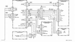 Title : G0mrf Uhf Wiring Diagram
Category : Wiring Diagram
Format : PDF
Title : G0mrf Uhf Wiring Diagram
Category : Wiring Diagram
Format : PDF