fuse-box-diagrams-anyone-help-needed-5series-net-wiring-diagram.pdf
1 / 81
100%
Download Full Diagram Via this App!!!!
Get Diagram Now! DOWNLOAD NOW
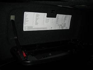 Title : Fuse Box Diagrams Anyone Help Needed 5series Net Wiring Diagram
Category : Wiring Diagram
Format : PDF
Title : Fuse Box Diagrams Anyone Help Needed 5series Net Wiring Diagram
Category : Wiring Diagram
Format : PDF