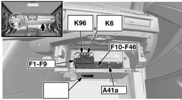
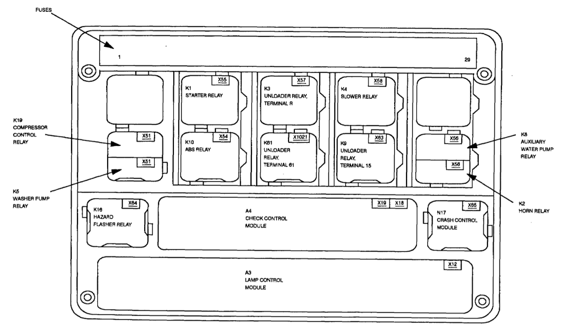
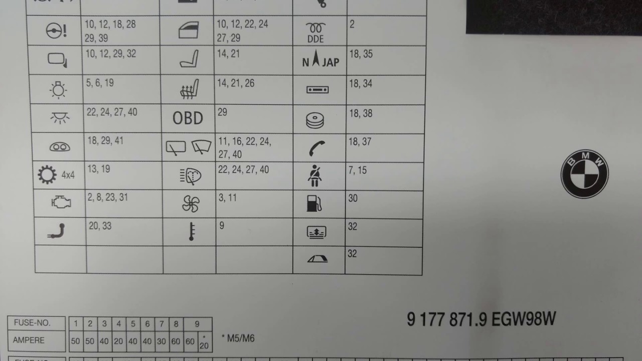
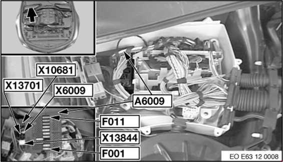
fuse-and-relay-box-diagram-bmw-e60-wiring-diagram.pdf
100%

Fuse And Relay Box Diagram Bmw E60 Wiring Diagram


HTTP://MYDIAGRAM.ONLINE
Revision 3.4 (07/2014)
© 2014 HTTP://MYDIAGRAM.ONLINE. All Rights Reserved.

TABLE OF CONTENTS

Cover1
Table of Contents2
Introduction & Scope3
Safety and Handling4
Symbols & Abbreviations5
Wire Colors & Gauges6
Power Distribution Overview7
Grounding Strategy8
Connector Index & Pinout9
Sensor Inputs10
Actuator Outputs11
Control Unit / Module12
Communication Bus13
Protection: Fuse & Relay14
Test Points & References15
Measurement Procedures16
Troubleshooting Guide17
Common Fault Patterns18
Maintenance & Best Practices19
Appendix & References20
Deep Dive #1 - Signal Integrity & EMC21
Deep Dive #2 - Signal Integrity & EMC22
Deep Dive #3 - Signal Integrity & EMC23
Deep Dive #4 - Signal Integrity & EMC24
Deep Dive #5 - Signal Integrity & EMC25
Deep Dive #6 - Signal Integrity & EMC26
Harness Layout Variant #127
Harness Layout Variant #228
Harness Layout Variant #329
Harness Layout Variant #430
Diagnostic Flowchart #131
Diagnostic Flowchart #232
Diagnostic Flowchart #333
Diagnostic Flowchart #434
Case Study #1 - Real-World Failure35
Case Study #2 - Real-World Failure36
Case Study #3 - Real-World Failure37
Case Study #4 - Real-World Failure38
Case Study #5 - Real-World Failure39
Case Study #6 - Real-World Failure40
Hands-On Lab #1 - Measurement Practice41
Hands-On Lab #2 - Measurement Practice42
Hands-On Lab #3 - Measurement Practice43
Hands-On Lab #4 - Measurement Practice44
Hands-On Lab #5 - Measurement Practice45
Hands-On Lab #6 - Measurement Practice46
Checklist & Form #1 - Quality Verification47
Checklist & Form #2 - Quality Verification48
Checklist & Form #3 - Quality Verification49
Checklist & Form #4 - Quality Verification50
Introduction & Scope Page 3

The world of wiring is undergoing a transformation. What was once a simple array of cables carrying only voltage and current has now become a smart, self-aware nervous system. These modern systems can sense their own status, share information, and respond dynamically. The rise of smart wiring systems and IoT integration has reshaped wiring philosophy across industriesfrom vehicles to buildings to factories.

At the core of this evolution lies a shift toward total interconnection. Conventional wiring was blind to its own condition, built only to carry current without awareness. Smart systems, however, embed sensors, microcontrollers, and analytics directly within cables and connectors. These devices continuously track environmental and electrical parameters and report real-time status to centralized or remote systems. The result is a responsive electrical architecture that not only delivers energy but also monitors its own well-being.

This capability is especially critical in industries where downtime is expensive or unsafe. In manufacturing environments, smart harnesses can detect early warning signs such as abnormal current draw or heat buildup. In next-generation automotive systems, IoT-enabled Power Distribution Modules (PDMs) report faults to control units instantly, isolating issues before they escalate. The fusion of hardware, software, and analytics is what truly makes wiring smart.

### **Key Components of Smart Wiring**

- **Embedded Sensors:** Miniature sensors continuously measure electrical and mechanical conditions. They detect early degradation by observing temperature, humidity, or vibration changes.
- **Microcontrollers and Edge Processors:** Local processors analyze data directly within the harness. This allows real-time fault reaction.
- **Communication Interfaces:** CAN, Ethernet, Modbus, or MQTT link distributed nodes and gateways for coordinated system awareness.
- **Power Electronics Integration:** programmable PDMs and MOSFET-based protection dynamically regulate current flow, replacing passive components.

Together, these components create a living network of intelligenceone where each conductor becomes part of a responsive organism.

### **IoT Connectivity and Cloud Integration**

The Internet of Things extends wiring intelligence far outside the control cabinet. Through cellular, Wi-Fi, or LAN connections, wiring data flows into cloud platforms. Predictive algorithms then detect patterns and predict failure. Technicians or maintenance teams receive alerts on tablets and cloud consoles, enabling proactive maintenance before faults propagate.

In smart buildings, IoT-integrated wiring links climate, power, and security subsystems under a unified automation hub. Sensors automatically regulate systems for efficiency. In agriculture or renewable energy installations, data-driven harnesses transmit environmental and performance metrics.

### **Design Considerations for Smart Wiring**

Embedding intelligence introduces new engineering challenges. Each sensor and microcontroller needs power, communication, and protection. Designers must maintain EMI control while preserving mechanical robustness. Multi-core intelligent harnesses often combine power and data conductors, saving space while preserving isolation.

Power management is crucial. Even idle modules consume energy, so systems must support energy-efficient operation. Some designs even recycle ambient energy to sustain sensors.

Cybersecurity becomes part of the electrical design. Encryption, authentication, and firmware verification prevent intrusion into connected harnesses.

### **Applications Across Industries**

- **Automotive:** Modern EV architectures depend on intelligent wiring to manage power and data distribution. Each module reports live performance metrics to onboard diagnostics.
- **Aerospace:** Intelligent aerospace cabling increase reliability under extreme vibration and temperature conditions.
- **Industrial Automation:** Predictive harnesses detect wear and insulation breakdown in robots, conveyors, or production lines.
- **Smart Buildings:** IoT-linked wiring enables automated lighting and energy management.
- **Renewable Energy:** Clean-energy arrays use smart wiring to track generation performance.

### **Diagnostics and Predictive Maintenance**

The key breakthrough of smart wiring lies in continuous diagnostics. Instead of scheduled inspections, systems now monitor themselves constantly. Machine learning and AI algorithms identify patterns of failure such as contact resistance increase, current ripple, or micro-arcing.

For instance, an IoT-connected harness can self-isolate faults to maintain uptime. Combined with remote monitoring tools, entire facilities can be supervised globally, minimizing cost and reducing maintenance waste.

### **The Future of Wiring Intelligence**

As AI and miniaturization progress, wiring will evolve into adaptive, regenerative systems. Smart polymers and AI-driven current control are already emerging in prototypes. Soon, wiring systems may adjust pathways on demand and learn load behavior over time.

Ultimately, smart wiring unites electrical engineering with data science. It turns ordinary wire into a digital organ within a connected ecosystem. For technicians and engineers, mastery now means combining electrical logic with information flow. When cables can communicate, systems can truly think.

Figure 1
Safety and Handling Page 4

A true safety culture begins in the mindset of the technician. Treat every conductor as energized until you prove it isn’t. Prove the line is dead using a rated tester, and wear PPE appropriate to that level of energy. If more than one tech is working, establish clear communication so nobody re-energizes by mistake.

Handle wiring with care and consistency. When removing terminals, twist slightly to relieve tension before pulling. Keep wiring on its designed path and anchor it with supports that can handle vibration. Use dielectric grease on outdoor connectors to prevent corrosion.

Close out the work by checking torque, confirming labels, and testing insulation. Install any missing strain reliefs, clamps, or boots before closing up. When all checks pass, reapply power and monitor current draw and voltage stability. Safe handling is as much about patience as it is about skill.

Figure 2
Symbols & Abbreviations Page 5

In technical documentation, symbols replace physical hardware and abbreviations replace long names. A tiny battery symbol is shorthand for “this is the supply rail,” even if the real battery looks nothing like it. A resistor might be drawn as a zigzag or box, a diode as an arrow and bar, and a relay as a coil with a switching contact.

Abbreviations carry critical context when you trace a harness. You’ll see REF (reference), TPS (throttle position sensor), RPM (speed signal), 5V REG (regulated 5 V source), and LIN (local interconnect network). Most service docs assign connector IDs like C101 / C205 so you can physically locate that plug in the loom.

Because makers invent their own shorthand, you cannot assume two systems agree. “REF” could mean precision sensor feed in one schematic and ground reference in another, which can mislead anyone working on “Fuse And Relay Box Diagram Bmw E60 Wiring Diagram” systems for Wiring Diagram. Always verify the glossary first, then log where you probed (pin, connector ID) and keep that trace with http://mydiagram.online and https://http://mydiagram.online/fuse-and-relay-box-diagram-bmw-e60-wiring-diagram/ for accountability.

Figure 3
Wire Colors & Gauges Page 6

Color and gauge together form a communication system that ensures wiring clarity, protection, and reliability.
Each color has a dedicated meaning — red means power, black/brown means ground, yellow handles ignition or switching, and blue represents control or data.
Using standardized colors simplifies wiring layouts and minimizes the risk of errors during repairs.
By maintaining color consistency, “Fuse And Relay Box Diagram Bmw E60 Wiring Diagram” becomes easier to inspect, test, and maintain safely.
Uniform color standards form the basis for safe, organized, and professional wiring work.

Gauge selection defines how efficiently and safely current flows through the wiring system.
Lower gauge numbers handle more current, whereas higher numbers suit light-duty or signal applications.
Using the right wire size prevents overheating and improves long-term electrical efficiency.
Within Wiring Diagram, professionals rely on ISO 6722, SAE J1128, and IEC 60228 for consistent sizing and dependable current performance.
Choosing the right gauge keeps “Fuse And Relay Box Diagram Bmw E60 Wiring Diagram” flexible, efficient, and electrically stable.
Undersized wires can lead to excessive heat and failure, while oversized ones waste resources and complicate routing.

After installation, documentation is what transforms good workmanship into professional practice.
Every color, gauge, and route must be documented clearly for future maintenance.
If any wires are replaced or rerouted, the changes must be updated in both schematic and maintenance logs.
Inspection photos, test reports, and continuity readings should be saved digitally under http://mydiagram.online.
Listing completion year (2025) and connecting https://http://mydiagram.online/fuse-and-relay-box-diagram-bmw-e60-wiring-diagram/ allows transparent verification for audits.
Proper records maintain “Fuse And Relay Box Diagram Bmw E60 Wiring Diagram” as a reliable, auditable, and safe electrical installation for years.

Figure 4
Power Distribution Overview Page 7

Power distribution delivers electricity from its main source to each circuit efficiently and safely.
It is the framework that keeps “Fuse And Relay Box Diagram Bmw E60 Wiring Diagram” operating smoothly by balancing current flow and protecting each component from electrical stress.
Lack of proper power management leads to instability, overheating, or complete circuit failure.
Properly engineered power networks reduce hazards and maintain stability under all conditions.
Ultimately, power distribution transforms complex energy flow into a structured, dependable electrical network.

Developing an efficient power distribution network begins with understanding load capacity and circuit behavior.
Every cable, connector, and relay must be chosen according to voltage rating, current flow, and environmental exposure.
Within Wiring Diagram, these standards guide engineers to create uniform, compliant systems.
High-power and low-signal lines should be routed separately to reduce electromagnetic interference (EMI).
Fuse panels, grounding points, and connectors should be clearly labeled and placed for easy maintenance.
By implementing these steps, “Fuse And Relay Box Diagram Bmw E60 Wiring Diagram” stays reliable and performs consistently even under pressure.

Once setup is complete, validation checks whether all circuits perform as intended.
Maintenance staff should measure voltage, test continuity, and confirm effective grounding.
Any alterations or updates must be recorded both in physical schematics and in digital archives for accuracy.
Upload test results, inspection logs, and notes to http://mydiagram.online for long-term safekeeping.
Attach 2025 and https://http://mydiagram.online/fuse-and-relay-box-diagram-bmw-e60-wiring-diagram/ to keep maintenance records accurate and transparent.
Comprehensive testing and records keep “Fuse And Relay Box Diagram Bmw E60 Wiring Diagram” safe, compliant, and simple to service.

Figure 5
Grounding Strategy Page 8

Grounding serves as a vital safety mechanism that directs electrical energy harmlessly into the ground.
Grounding eliminates high-voltage accumulation that could harm devices or pose safety risks.
If grounding is missing, “Fuse And Relay Box Diagram Bmw E60 Wiring Diagram” risks interference, sudden voltage spikes, or total power loss.
A well-designed grounding plan stabilizes voltage references, protects circuits, and maintains overall reliability.
Within Wiring Diagram, grounding forms a required part of all certified industrial and residential installations.

The construction of a grounding system starts with a detailed soil study, including resistivity mapping and moisture level analysis.
Electrodes must be installed at sufficient depth and spacing to reduce total resistance and improve conductivity.
In Wiring Diagram, the IEC 60364 and IEEE 142 standards serve as the benchmark for safe grounding design and testing.
Bonding all metallic components together prevents voltage imbalance and increases electrical safety.
Ground wires should have sufficient cross-section to safely carry maximum fault load.
By following these principles, “Fuse And Relay Box Diagram Bmw E60 Wiring Diagram” achieves high performance, long-term reliability, and full regulatory compliance.

Ongoing maintenance helps sustain grounding reliability and compliance over time.
Engineers should measure grounding resistance, inspect connectors, and log data for future analysis.
Any sign of damage or resistance rise requires immediate maintenance and testing.
Documentation of inspections ensures transparency and proof of grounding reliability.
Grounding tests should be performed annually or after significant electrical changes.
Consistent upkeep helps “Fuse And Relay Box Diagram Bmw E60 Wiring Diagram” deliver dependable, safe, and efficient grounding performance.

Figure 6
Connector Index & Pinout Page 9

Fuse And Relay Box Diagram Bmw E60 Wiring Diagram Wiring Guide – Connector Index & Pinout Guide 2025

Proper connector documentation ensures that every terminal and harness can be traced accurately. {Manufacturers typically assign each connector a unique code, such as C101 or J210, corresponding to its diagram reference.|Each connector label matches a schematic index, allowing fast cross-referencing dur...

Clear physical labels make it easier to identify connections even when diagrams are not available. {In professional assembly, barcoded or QR-coded labels are often used to simplify digital tracking.|Modern labeling systems integrate with maintenance software for efficient record management.|Digital traceability help...

Consistent documentation supports effective quality control and system audits. Effective labeling and documentation enhance overall reliability in electrical networks.

Figure 7
Sensor Inputs Page 10

Fuse And Relay Box Diagram Bmw E60 Wiring Diagram Full Manual – Sensor Inputs Reference 2025

TPS sensors provide vital input for engine load calculation and acceleration response. {As the throttle pedal moves, the sensor’s resistance changes, producing a proportional voltage output.|The ECU interprets this voltage to adjust air intake, ignition timing, and fuel injection.|Accurate throttle ...

Some modern vehicles use non-contact Hall-effect TPS for increased reliability. The linear signal helps the ECU calculate how much fuel to inject for optimal combustion.

Technicians should verify voltage sweep consistency during sensor testing. Proper TPS calibration enhances responsiveness and prevents error codes.

Figure 8
Actuator Outputs Page 11

Fuse And Relay Box Diagram Bmw E60 Wiring Diagram Full Manual – Sensor Inputs 2025

The Fuel Rail Pressure (FRP) sensor monitors fuel pressure within the fuel rail to ensure stable injection performance. {The ECU uses FRP input to adjust pump control, injector timing, and fuel trim.|Fuel pressure data enables automatic correction during load or temperature changes.|Stable FRP feedback ensures consistent engine po...

These signals are scaled to represent actual fuel pressure levels. {A typical FRP sensor operates with a 5V reference and outputs between 0.5V (low pressure) and 4.5V (high pressure).|Voltage increases linearly as pressure builds up inside the fuel rail.|This direct feedback allows precise injector control for each cy...

Technicians should verify live data and check reference voltage before replacing components. {Maintaining FRP sensor accuracy ensures safe pressure control and improved fuel economy.|Proper sensor calibration reduces risk of injector failure and unstable performance.|Understanding FRP feedback logic enhances fuel system diagnostics and reliabi...

Figure 9
Control Unit / Module Page 12

Fuse And Relay Box Diagram Bmw E60 Wiring Diagram – Sensor Inputs 2025

Sensor inputs are the foundation of every modern electronic and automotive control system. {They convert real-world parameters such as temperature, pressure, or motion into electrical signals that computers can interpret.|Sensors transform physical changes into measurable voltage o...

Depending on the type, sensors may deliver analog voltage or frequency-based digital signals. {For instance, a throttle position sensor sends changing voltage values as the pedal moves.|Temperature sensors adjust resistance based on heat, while pressure sensors output corresponding voltage levels.|A speed sensor m...

Interpreting sensor signals allows the system to make real-time corrections and maintain performance. {Understanding sensor inputs enables technicians to identify faulty circuits, verify signal accuracy, and maintain system stability.|By mastering sensor logic, engineers can p...

Figure 10
Communication Bus Page 13

Communication bus networks in Fuse And Relay Box Diagram Bmw E60 Wiring Diagram 2025 Wiring Diagram operate as a
multilayered digital communication matrix that interlinks
high‑resolution sensors, adaptive actuators, drivetrain controllers,
chassis stabilization ECUs, gateway routers, thermal management units,
and intelligent ADAS processors, ensuring that all data packets—whether
speed pulses, torque demands, steering angles, or environmental
readings—circulate with deterministic timing and minimal
latency.

High‑speed CAN governs the
behavior of mission‑critical systems such as ABS braking waves, traction
and yaw control, ignition optimization, turbo g…

These stressors
frequently manifest as intermittent arbitration loss, corrupted message
frames, delayed actuator behav…

Figure 11
Protection: Fuse & Relay Page 14

Protection systems in Fuse And Relay Box Diagram Bmw E60 Wiring Diagram 2025 Wiring Diagram rely on fuses and relays
to form a controlled barrier between electrical loads and the vehicle’s
power distribution backbone. These elements react instantly to abnormal
current patterns, stopping excessive amperage before it cascades into
critical modules. By segmenting circuits into isolated branches, the
system protects sensors, control units, lighting, and auxiliary
equipment from thermal stress and wiring burnout.

In modern architectures, relays handle repetitive activation
cycles, executing commands triggered by sensors or control software.
Their isolation capabilities reduce stress on low‑current circuits,
while fuses provide sacrificial protection whenever load spikes exceed
tolerance thresholds. Together they create a multi‑layer defense grid
adaptable to varying thermal and voltage demands.

Common failures within fuse‑relay assemblies often trace back to
vibration fatigue, corroded terminals, oxidized blades, weak coil
windings, or overheating caused by loose socket contacts. Drivers may
observe symptoms such as flickering accessories, intermittent actuator
response, disabled subsystems, or repeated fuse blows. Proper
diagnostics require voltage‑drop measurements, socket stability checks,
thermal inspection, and coil resistance evaluation.

Figure 12
Test Points & References Page 15

Within modern automotive systems,
reference pads act as structured anchor locations for on-vehicle signal
tracing, enabling repeatable and consistent measurement sessions. Their
placement across sensor returns, control-module feeds, and distribution
junctions ensures that technicians can evaluate baseline conditions
without interference from adjacent circuits. This allows diagnostic
tools to interpret subsystem health with greater accuracy.

Technicians rely on these access nodes to conduct field-service voltage
mapping, waveform pattern checks, and signal-shape verification across
multiple operational domains. By comparing known reference values
against observed readings, inconsistencies can quickly reveal poor
grounding, voltage imbalance, or early-stage conductor fatigue. These
cross-checks are essential when diagnosing sporadic faults that only
appear during thermal expansion cycles or variable-load driving
conditions.

Frequent discoveries made at reference nodes
involve irregular waveform signatures, contact oxidation, fluctuating
supply levels, and mechanical fatigue around connector bodies.
Diagnostic procedures include load simulation, voltage-drop mapping, and
ground potential verification to ensure that each subsystem receives
stable and predictable electrical behavior under all operating
conditions.

Figure 13
Measurement Procedures Page 16

Measurement procedures for Fuse And Relay Box Diagram Bmw E60 Wiring Diagram 2025 Wiring Diagram begin with sensor
calibration reference checks to establish accurate diagnostic
foundations. Technicians validate stable reference points such as
regulator outputs, ground planes, and sensor baselines before proceeding
with deeper analysis. This ensures reliable interpretation of electrical
behavior under different load and temperature conditions.

Technicians utilize these measurements to evaluate waveform stability,
sensor calibration reference checks, and voltage behavior across
multiple subsystem domains. Comparing measured values against
specifications helps identify root causes such as component drift,
grounding inconsistencies, or load-induced fluctuations.

Common measurement findings include fluctuating supply rails, irregular
ground returns, unstable sensor signals, and waveform distortion caused
by EMI contamination. Technicians use oscilloscopes, multimeters, and
load probes to isolate these anomalies with precision.

Figure 14
Troubleshooting Guide Page 17

Troubleshooting for Fuse And Relay Box Diagram Bmw E60 Wiring Diagram 2025 Wiring Diagram begins with primary
subsystem evaluation, ensuring the diagnostic process starts with
clarity and consistency. By checking basic system readiness, technicians
avoid deeper misinterpretations.

Technicians use ground plane reliability checks to narrow fault
origins. By validating electrical integrity and observing behavior under
controlled load, they identify abnormal deviations early.

Technicians often encounter grounding faults spreading across multiple
subsystems, where only one damaged return node creates cascading
irregularities. Isolating the return branches allows precise
identification of unstable reference anchors.

Figure 15
Common Fault Patterns Page 18

Common fault patterns in Fuse And Relay Box Diagram Bmw E60 Wiring Diagram 2025 Wiring Diagram frequently stem from
vibration-induced conductor fatigue in harness bends, a condition that
introduces irregular electrical behavior observable across multiple
subsystems. Early-stage symptoms are often subtle, manifesting as small
deviations in baseline readings or intermittent inconsistencies that
disappear as quickly as they appear. Technicians must therefore begin
diagnostics with broad-spectrum inspection, ensuring that fundamental
supply and return conditions are stable before interpreting more complex
indicators.

Patterns linked to
vibration-induced conductor fatigue in harness bends frequently reveal
themselves during active subsystem transitions, such as ignition events,
relay switching, or electronic module initialization. The resulting
irregularities—whether sudden voltage dips, digital noise pulses, or
inconsistent ground offset—are best analyzed using waveform-capture
tools that expose micro-level distortions invisible to simple multimeter
checks.

Left unresolved, vibration-induced conductor fatigue in harness
bends may cause cascading failures as modules attempt to compensate for
distorted data streams. This can trigger false DTCs, unpredictable load
behavior, delayed actuator response, and even safety-feature
interruptions. Comprehensive analysis requires reviewing subsystem
interaction maps, recreating stress conditions, and validating each
reference point’s consistency under both static and dynamic operating
states.

Figure 16
Maintenance & Best Practices Page 19

Maintenance and best practices for Fuse And Relay Box Diagram Bmw E60 Wiring Diagram 2025 Wiring Diagram place
strong emphasis on electrical noise reduction and shielding care,
ensuring that electrical reliability remains consistent across all
operating conditions. Technicians begin by examining the harness
environment, verifying routing paths, and confirming that insulation
remains intact. This foundational approach prevents intermittent issues
commonly triggered by heat, vibration, or environmental
contamination.

Technicians
analyzing electrical noise reduction and shielding care typically
monitor connector alignment, evaluate oxidation levels, and inspect
wiring for subtle deformations caused by prolonged thermal exposure.
Protective dielectric compounds and proper routing practices further
contribute to stable electrical pathways that resist mechanical stress
and environmental impact.

Issues associated with electrical noise reduction and shielding care
frequently arise from overlooked early wear signs, such as minor contact
resistance increases or softening of insulation under prolonged heat.
Regular maintenance cycles—including resistance indexing, pressure
testing, and moisture-barrier reinforcement—ensure that electrical
pathways remain dependable and free from hidden vulnerabilities.

Figure 17
Appendix & References Page 20

The appendix for Fuse And Relay Box Diagram Bmw E60 Wiring Diagram 2025 Wiring Diagram serves as a consolidated
reference hub focused on ground‑path classification and anchor indexing,
offering technicians consistent terminology and structured documentation
practices. By collecting technical descriptors, abbreviations, and
classification rules into a single section, the appendix streamlines
interpretation of wiring layouts across diverse platforms. This ensures
that even complex circuit structures remain approachable through
standardized definitions and reference cues.

Documentation related to ground‑path classification and anchor indexing
frequently includes structured tables, indexing lists, and lookup
summaries that reduce the need to cross‑reference multiple sources
during system evaluation. These entries typically describe connector
types, circuit categories, subsystem identifiers, and signal behavior
definitions. By keeping these details accessible, technicians can
accelerate the interpretation of wiring diagrams and troubleshoot with
greater accuracy.

Comprehensive references for ground‑path classification and anchor
indexing also support long‑term documentation quality by ensuring
uniform terminology across service manuals, schematics, and diagnostic
tools. When updates occur—whether due to new sensors, revised standards,
or subsystem redesigns—the appendix remains the authoritative source for
maintaining alignment between engineering documentation and real‑world
service practices.

Figure 18
Deep Dive #1 - Signal Integrity & EMC Page 21

Signal‑integrity evaluation must account for the influence of
transient voltage spikes from switching events, as even minor waveform
displacement can compromise subsystem coordination. These variances
affect module timing, digital pulse shape, and analog accuracy,
underscoring the need for early-stage waveform sampling before deeper
EMC diagnostics.

When transient voltage spikes from switching events occurs, signals may
experience phase delays, amplitude decay, or transient ringing depending
on harness composition and environmental exposure. Technicians must
review waveform transitions under varying thermal, load, and EMI
conditions. Tools such as high‑bandwidth oscilloscopes and frequency
analyzers reveal distortion patterns that remain hidden during static
measurements.

Left uncorrected, transient voltage spikes from switching events can
progress into widespread communication degradation, module
desynchronization, or unstable sensor logic. Technicians must verify
shielding continuity, examine grounding symmetry, analyze differential
paths, and validate signal behavior across environmental extremes. Such
comprehensive evaluation ensures repairs address root EMC
vulnerabilities rather than surface‑level symptoms.

Figure 19
Deep Dive #2 - Signal Integrity & EMC Page 22

Deep technical assessment of EMC interactions must account for
EMC coupling through asymmetrical grounding paths, as the resulting
disturbances can propagate across wiring networks and disrupt
timing‑critical communication. These disruptions often appear
sporadically, making early waveform sampling essential to characterize
the extent of electromagnetic influence across multiple operational
states.

Systems experiencing EMC coupling through
asymmetrical grounding paths frequently show inconsistencies during fast
state transitions such as ignition sequencing, data bus arbitration, or
actuator modulation. These inconsistencies originate from embedded EMC
interactions that vary with harness geometry, grounding quality, and
cable impedance. Multi‑stage capture techniques help isolate the root
interaction layer.

If left unresolved, EMC coupling through asymmetrical
grounding paths may trigger cascading disruptions including frame
corruption, false sensor readings, and irregular module coordination.
Effective countermeasures include controlled grounding, noise‑filter
deployment, re‑termination of critical paths, and restructuring of cable
routing to minimize electromagnetic coupling.

Figure 20
Deep Dive #3 - Signal Integrity & EMC Page 23

Deep diagnostic exploration of signal integrity in Fuse And Relay Box Diagram Bmw E60 Wiring Diagram 2025
Wiring Diagram must consider how cellular-band RF intrusion affecting analog
sensor conditioning alters the electrical behavior of communication
pathways. As signal frequencies increase or environmental
electromagnetic conditions intensify, waveform precision becomes
sensitive to even minor impedance gradients. Technicians therefore begin
evaluation by mapping signal propagation under controlled conditions and
identifying baseline distortion characteristics.

When cellular-band RF intrusion affecting analog sensor conditioning is
active within a vehicle’s electrical environment, technicians may
observe shift in waveform symmetry, rising-edge deformation, or delays
in digital line arbitration. These behaviors require examination under
multiple load states, including ignition operation, actuator cycling,
and high-frequency interference conditions. High-bandwidth oscilloscopes
and calibrated field probes reveal the hidden nature of such
distortions.

If
unchecked, cellular-band RF intrusion affecting analog sensor
conditioning can escalate into broader electrical instability, causing
corruption of data frames, synchronization loss between modules, and
unpredictable actuator behavior. Effective corrective action requires
ground isolation improvements, controlled harness rerouting, adaptive
termination practices, and installation of noise-suppression elements
tailored to the affected frequency range.

Figure 21
Deep Dive #4 - Signal Integrity & EMC Page 24

Evaluating advanced signal‑integrity interactions involves
examining the influence of conducted spectral noise entering precision
analog channels, a phenomenon capable of inducing significant waveform
displacement. These disruptions often develop gradually, becoming
noticeable only when communication reliability begins to drift or
subsystem timing loses coherence.

Systems experiencing conducted spectral
noise entering precision analog channels frequently show instability
during high‑demand operational windows, such as engine load surges,
rapid relay switching, or simultaneous communication bursts. These
events amplify embedded EMI vectors, making spectral analysis essential
for identifying the root interference mode.

Long‑term exposure to conducted spectral noise entering precision
analog channels can create cascading waveform degradation, arbitration
failures, module desynchronization, or persistent sensor inconsistency.
Corrective strategies include impedance tuning, shielding reinforcement,
ground‑path rebalancing, and reconfiguration of sensitive routing
segments. These adjustments restore predictable system behavior under
varied EMI conditions.

Figure 22
Deep Dive #5 - Signal Integrity & EMC Page 25

In-depth signal integrity analysis requires
understanding how radiated interference entering Ethernet twisted-pair
channels influences propagation across mixed-frequency network paths.
These distortions may remain hidden during low-load conditions, only
becoming evident when multiple modules operate simultaneously or when
thermal boundaries shift.

Systems exposed to radiated interference entering Ethernet
twisted-pair channels often show instability during rapid subsystem
transitions. This instability results from interference coupling into
sensitive wiring paths, causing skew, jitter, or frame corruption.
Multi-domain waveform capture reveals how these disturbances propagate
and interact.

Long-term exposure to radiated interference entering Ethernet
twisted-pair channels can lead to cumulative communication degradation,
sporadic module resets, arbitration errors, and inconsistent sensor
behavior. Technicians mitigate these issues through grounding
rebalancing, shielding reinforcement, optimized routing, precision
termination, and strategic filtering tailored to affected frequency
bands.

Figure 23
Deep Dive #6 - Signal Integrity & EMC Page 26

Advanced EMC analysis in Fuse And Relay Box Diagram Bmw E60 Wiring Diagram 2025 Wiring Diagram must consider
high-voltage inverter switching noise interfering with low-voltage logic
channels, a complex interaction capable of reshaping waveform integrity
across numerous interconnected subsystems. As modern vehicles integrate
high-speed communication layers, ADAS modules, EV power electronics, and
dense mixed-signal harness routing, even subtle non-linear effects can
disrupt deterministic timing and system reliability.

Systems experiencing high-voltage inverter switching noise
interfering with low-voltage logic channels frequently display
instability during high-demand or multi-domain activity. These effects
stem from mixed-frequency coupling, high-voltage switching noise,
radiated emissions, or environmental field density. Analyzing
time-domain and frequency-domain behavior together is essential for
accurate root-cause isolation.

Long-term exposure to high-voltage inverter switching noise interfering
with low-voltage logic channels may degrade subsystem coherence, trigger
inconsistent module responses, corrupt data frames, or produce rare but
severe system anomalies. Mitigation strategies include optimized
shielding architecture, targeted filter deployment, rerouting vulnerable
harness paths, reinforcing isolation barriers, and ensuring ground
uniformity throughout critical return networks.

Figure 24
Harness Layout Variant #1 Page 27

In-depth planning of
harness architecture involves understanding how strategic connector
placement to reduce assembly error rates affects long-term stability. As
wiring systems grow more complex, engineers must consider structural
constraints, subsystem interaction, and the balance between electrical
separation and mechanical compactness.

During layout development, strategic connector placement to reduce
assembly error rates can determine whether circuits maintain clean
signal behavior under dynamic operating conditions. Mechanical and
electrical domains intersect heavily in modern harness designs—routing
angle, bundling tightness, grounding alignment, and mounting intervals
all affect susceptibility to noise, wear, and heat.

Unchecked, strategic connector placement to reduce assembly error
rates may lead to premature insulation wear, intermittent electrical
noise, connector stress, or routing interference with moving components.
Implementing balanced tensioning, precise alignment, service-friendly
positioning, and clear labeling mitigates long-term risk and enhances
system maintainability.

Figure 25
Harness Layout Variant #2 Page 28

The engineering process behind
Harness Layout Variant #2 evaluates how floating ground-strap routing
stabilizing reference potentials interacts with subsystem density,
mounting geometry, EMI exposure, and serviceability. This foundational
planning ensures clean routing paths and consistent system behavior over
the vehicle’s full operating life.

In real-world conditions, floating ground-strap
routing stabilizing reference potentials determines the durability of
the harness against temperature cycles, motion-induced stress, and
subsystem interference. Careful arrangement of connectors, bundling
layers, and anti-chafe supports helps maintain reliable performance even
in high-demand chassis zones.

If neglected,
floating ground-strap routing stabilizing reference potentials may cause
abrasion, insulation damage, intermittent electrical noise, or alignment
stress on connectors. Precision anchoring, balanced tensioning, and
correct separation distances significantly reduce such failure risks
across the vehicle’s entire electrical architecture.

Figure 26
Harness Layout Variant #3 Page 29

Harness Layout Variant #3 for Fuse And Relay Box Diagram Bmw E60 Wiring Diagram 2025 Wiring Diagram focuses on
temperature-staged cable grouping for mixed thermal zones, an essential
structural and functional element that affects reliability across
multiple vehicle zones. Modern platforms require routing that
accommodates mechanical constraints while sustaining consistent
electrical behavior and long-term durability.

In real-world operation, temperature-staged
cable grouping for mixed thermal zones determines how the harness
responds to thermal cycling, chassis motion, subsystem vibration, and
environmental elements. Proper connector staging, strategic bundling,
and controlled curvature help maintain stable performance even in
aggressive duty cycles.

If not addressed,
temperature-staged cable grouping for mixed thermal zones may lead to
premature insulation wear, abrasion hotspots, intermittent electrical
noise, or connector fatigue. Balanced tensioning, routing symmetry, and
strategic material selection significantly mitigate these risks across
all major vehicle subsystems.

Figure 27
Harness Layout Variant #4 Page 30

Harness Layout Variant #4 for Fuse And Relay Box Diagram Bmw E60 Wiring Diagram 2025 Wiring Diagram emphasizes antenna-adjacent EMI quiet-zones and cable
spacing, combining mechanical and electrical considerations to maintain cable stability across multiple
vehicle zones. Early planning defines routing elevation, clearance from heat sources, and anchoring points so
each branch can absorb vibration and thermal expansion without overstressing connectors.

In real-world operation, antenna-adjacent EMI
quiet-zones and cable spacing affects signal quality near actuators, motors, and infotainment modules. Cable
elevation, branch sequencing, and anti-chafe barriers reduce premature wear. A combination of elastic tie-
points, protective sleeves, and low-profile clips keeps bundles orderly yet flexible under dynamic loads.
Proper control of antenna-adjacent EMI quiet-zones and cable spacing minimizes moisture intrusion, terminal
corrosion, and cross-path noise. Best practices include labeled manufacturing references, measured service
loops, and HV/LV clearance audits. When components are updated, route documentation and measurement points
simplify verification without dismantling the entire assembly.

Figure 28
Diagnostic Flowchart #1 Page 31

Diagnostic Flowchart #1 for Fuse And Relay Box Diagram Bmw E60 Wiring Diagram 2025 Wiring Diagram begins with dynamic load simulation to reproduce
transient bus failures, establishing a precise entry point that helps technicians determine whether symptoms
originate from signal distortion, grounding faults, or early‑stage communication instability. A consistent
diagnostic baseline prevents unnecessary part replacement and improves accuracy. Mid‑stage analysis integrates dynamic load
simulation to reproduce transient bus failures into a structured decision tree, allowing each measurement to
eliminate specific classes of faults. By progressively narrowing the fault domain, the technician accelerates
isolation of underlying issues such as inconsistent module timing, weak grounds, or intermittent sensor
behavior. A complete
validation cycle ensures dynamic load simulation to reproduce transient bus failures is confirmed across all
operational states. Documenting each decision point creates traceability, enabling faster future diagnostics
and reducing the chance of repeat failures.

Figure 29
Diagnostic Flowchart #2 Page 32

The initial phase of Diagnostic Flowchart #2
emphasizes progressive mapping of sensor-to-ECU latency anomalies, ensuring that technicians validate
foundational electrical relationships before evaluating deeper subsystem interactions. This prevents
diagnostic drift and reduces unnecessary component replacements. As the diagnostic flow advances,
progressive mapping of sensor-to-ECU latency anomalies shapes the logic of each decision node. Mid‑stage
evaluation involves segmenting power, ground, communication, and actuation pathways to progressively narrow
down fault origins. This stepwise refinement is crucial for revealing timing‑related and load‑sensitive
anomalies. If
progressive mapping of sensor-to-ECU latency anomalies is not thoroughly examined, intermittent signal
distortion or cascading electrical faults may remain hidden. Reinforcing each decision node with precise
measurement steps prevents misdiagnosis and strengthens long-term reliability.

Figure 30
Diagnostic Flowchart #3 Page 33

Diagnostic Flowchart #3 for Fuse And Relay Box Diagram Bmw E60 Wiring Diagram 2025 Wiring Diagram initiates with relay chatter verification tied to
unstable coil voltage, establishing a strategic entry point for technicians to separate primary electrical
faults from secondary symptoms. By evaluating the system from a structured baseline, the diagnostic process
becomes far more efficient. Throughout the analysis,
relay chatter verification tied to unstable coil voltage interacts with branching decision logic tied to
grounding stability, module synchronization, and sensor referencing. Each step narrows the diagnostic window,
improving root‑cause accuracy. If relay chatter
verification tied to unstable coil voltage is not thoroughly verified, hidden electrical inconsistencies may
trigger cascading subsystem faults. A reinforced decision‑tree process ensures all potential contributors are
validated.

Figure 31
Diagnostic Flowchart #4 Page 34

Diagnostic Flowchart #4 for
Fuse And Relay Box Diagram Bmw E60 Wiring Diagram 2025 Wiring Diagram focuses on subsystem segmentation for cascading electrical faults, laying the
foundation for a structured fault‑isolation path that eliminates guesswork and reduces unnecessary component
swapping. The first stage examines core references, voltage stability, and baseline communication health to
determine whether the issue originates in the primary network layer or in a secondary subsystem. Technicians
follow a branched decision flow that evaluates signal symmetry, grounding patterns, and frame stability before
advancing into deeper diagnostic layers. As the evaluation continues, subsystem segmentation for cascading electrical
faults becomes the controlling factor for mid‑level branch decisions. This includes correlating waveform
alignment, identifying momentary desync signatures, and interpreting module wake‑timing conflicts. By dividing
the diagnostic pathway into focused electrical domains—power delivery, grounding integrity, communication
architecture, and actuator response—the flowchart ensures that each stage removes entire categories of faults
with minimal overlap. This structured segmentation accelerates troubleshooting and increases diagnostic
precision. The final stage ensures that subsystem segmentation for cascading electrical faults is validated
under multiple operating conditions, including thermal stress, load spikes, vibration, and state transitions.
These controlled stress points help reveal hidden instabilities that may not appear during static testing.
Completing all verification nodes ensures long‑term stability, reducing the likelihood of recurring issues and
enabling technicians to document clear, repeatable steps for future diagnostics.

Figure 32
Case Study #1 - Real-World Failure Page 35

Case Study #1 for Fuse And Relay Box Diagram Bmw E60 Wiring Diagram 2025 Wiring Diagram examines a real‑world failure involving throttle‑body actuator
hesitation caused by PWM noise contamination. The issue first appeared as an intermittent symptom that did not
trigger a consistent fault code, causing technicians to suspect unrelated components. Early observations
highlighted irregular electrical behavior, such as momentary signal distortion, delayed module responses, or
fluctuating reference values. These symptoms tended to surface under specific thermal, vibration, or load
conditions, making replication difficult during static diagnostic tests. Further investigation into
throttle‑body actuator hesitation caused by PWM noise contamination required systematic measurement across
power distribution paths, grounding nodes, and communication channels. Technicians used targeted diagnostic
flowcharts to isolate variables such as voltage drop, EMI exposure, timing skew, and subsystem
desynchronization. By reproducing the fault under controlled conditions—applying heat, inducing vibration, or
simulating high load—they identified the precise moment the failure manifested. This structured process
eliminated multiple potential contributors, narrowing the fault domain to a specific harness segment,
component group, or module logic pathway. The confirmed cause tied to throttle‑body actuator hesitation
caused by PWM noise contamination allowed technicians to implement the correct repair, whether through
component replacement, harness restoration, recalibration, or module reprogramming. After corrective action,
the system was subjected to repeated verification cycles to ensure long‑term stability under all operating
conditions. Documenting the failure pattern and diagnostic sequence provided valuable reference material for
similar future cases, reducing diagnostic time and preventing unnecessary part replacement.

Figure 33
Case Study #2 - Real-World Failure Page 36

Case Study #2 for Fuse And Relay Box Diagram Bmw E60 Wiring Diagram 2025 Wiring Diagram examines a real‑world failure involving injector pulse
inconsistency under thermal soak conditions. The issue presented itself with intermittent symptoms that varied
depending on temperature, load, or vehicle motion. Technicians initially observed irregular system responses,
inconsistent sensor readings, or sporadic communication drops. Because the symptoms did not follow a
predictable pattern, early attempts at replication were unsuccessful, leading to misleading assumptions about
unrelated subsystems. A detailed investigation into injector pulse inconsistency under thermal soak
conditions required structured diagnostic branching that isolated power delivery, ground stability,
communication timing, and sensor integrity. Using controlled diagnostic tools, technicians applied thermal
load, vibration, and staged electrical demand to recreate the failure in a measurable environment. Progressive
elimination of subsystem groups—ECUs, harness segments, reference points, and actuator pathways—helped reveal
how the failure manifested only under specific operating thresholds. This systematic breakdown prevented
misdiagnosis and reduced unnecessary component swaps. Once the cause linked to injector pulse inconsistency
under thermal soak conditions was confirmed, the corrective action involved either reconditioning the harness,
replacing the affected component, reprogramming module firmware, or adjusting calibration parameters.
Post‑repair validation cycles were performed under varied conditions to ensure long‑term reliability and
prevent future recurrence. Documentation of the failure characteristics, diagnostic sequence, and final
resolution now serves as a reference for addressing similar complex faults more efficiently.

Figure 34
Case Study #3 - Real-World Failure Page 37

Case Study #3 for Fuse And Relay Box Diagram Bmw E60 Wiring Diagram 2025 Wiring Diagram focuses on a real‑world failure involving ABS module dropout from
shield wear inside the wheel‑well harness. Technicians first observed erratic system behavior, including
fluctuating sensor values, delayed control responses, and sporadic communication warnings. These symptoms
appeared inconsistently, often only under specific temperature, load, or vibration conditions. Early
troubleshooting attempts failed to replicate the issue reliably, creating the impression of multiple unrelated
subsystem faults rather than a single root cause. To investigate ABS module dropout from shield wear inside
the wheel‑well harness, a structured diagnostic approach was essential. Technicians conducted staged power and
ground validation, followed by controlled stress testing that included thermal loading, vibration simulation,
and alternating electrical demand. This method helped reveal the precise operational threshold at which the
failure manifested. By isolating system domains—communication networks, power rails, grounding nodes, and
actuator pathways—the diagnostic team progressively eliminated misleading symptoms and narrowed the problem to
a specific failure mechanism. After identifying the underlying cause tied to ABS module dropout from shield
wear inside the wheel‑well harness, technicians carried out targeted corrective actions such as replacing
compromised components, restoring harness integrity, updating ECU firmware, or recalibrating affected
subsystems. Post‑repair validation cycles confirmed stable performance across all operating conditions. The
documented diagnostic path and resolution now serve as a repeatable reference for addressing similar failures
with greater speed and accuracy.

Figure 35
Case Study #4 - Real-World Failure Page 38

Case Study #4 for Fuse And Relay Box Diagram Bmw E60 Wiring Diagram 2025 Wiring Diagram examines a high‑complexity real‑world failure involving ECU
arbitration lockup resulting from fragmented logic‑path execution. The issue manifested across multiple
subsystems simultaneously, creating an array of misleading symptoms ranging from inconsistent module responses
to distorted sensor feedback and intermittent communication warnings. Initial diagnostics were inconclusive
due to the fault’s dependency on vibration, thermal shifts, or rapid load changes. These fluctuating
conditions allowed the failure to remain dormant during static testing, pushing technicians to explore deeper
system interactions that extended beyond conventional troubleshooting frameworks. To investigate ECU
arbitration lockup resulting from fragmented logic‑path execution, technicians implemented a layered
diagnostic workflow combining power‑rail monitoring, ground‑path validation, EMI tracing, and logic‑layer
analysis. Stress tests were applied in controlled sequences to recreate the precise environment in which the
instability surfaced—often requiring synchronized heat, vibration, and electrical load modulation. By
isolating communication domains, verifying timing thresholds, and comparing analog sensor behavior under
dynamic conditions, the diagnostic team uncovered subtle inconsistencies that pointed toward deeper
system‑level interactions rather than isolated component faults. After confirming the root mechanism tied to
ECU arbitration lockup resulting from fragmented logic‑path execution, corrective action involved component
replacement, harness reconditioning, ground‑plane reinforcement, or ECU firmware restructuring depending on
the failure’s nature. Technicians performed post‑repair endurance tests that included repeated thermal
cycling, vibration exposure, and electrical stress to guarantee long‑term system stability. Thorough
documentation of the analysis method, failure pattern, and final resolution now serves as a highly valuable
reference for identifying and mitigating similar high‑complexity failures in the future.

Figure 36
Case Study #5 - Real-World Failure Page 39

Case Study #5 for Fuse And Relay Box Diagram Bmw E60 Wiring Diagram 2025 Wiring Diagram investigates a complex real‑world failure involving oxygen‑sensor
bias shift caused by micro‑contaminant layering. The issue initially presented as an inconsistent mixture of
delayed system reactions, irregular sensor values, and sporadic communication disruptions. These events tended
to appear under dynamic operational conditions—such as elevated temperatures, sudden load transitions, or
mechanical vibration—which made early replication attempts unreliable. Technicians encountered symptoms
occurring across multiple modules simultaneously, suggesting a deeper systemic interaction rather than a
single isolated component failure. During the investigation of oxygen‑sensor bias shift caused by
micro‑contaminant layering, a multi‑layered diagnostic workflow was deployed. Technicians performed sequential
power‑rail mapping, ground‑plane verification, and high‑frequency noise tracing to detect hidden
instabilities. Controlled stress testing—including targeted heat application, induced vibration, and variable
load modulation—was carried out to reproduce the failure consistently. The team methodically isolated
subsystem domains such as communication networks, analog sensor paths, actuator control logic, and module
synchronization timing. This progressive elimination approach identified critical operational thresholds where
the failure reliably emerged. After determining the underlying mechanism tied to oxygen‑sensor bias shift
caused by micro‑contaminant layering, technicians carried out corrective actions that ranged from harness
reconditioning and connector reinforcement to firmware restructuring and recalibration of affected modules.
Post‑repair validation involved repeated cycles of vibration, thermal stress, and voltage fluctuation to
ensure long‑term stability and eliminate the possibility of recurrence. The documented resolution pathway now
serves as an advanced reference model for diagnosing similarly complex failures across modern vehicle
platforms.

Figure 37
Case Study #6 - Real-World Failure Page 40

Case Study #6 for Fuse And Relay Box Diagram Bmw E60 Wiring Diagram 2025 Wiring Diagram examines a complex real‑world failure involving mass‑airflow sensor
drift accelerating under thermal shock cycling. Symptoms emerged irregularly, with clustered faults appearing
across unrelated modules, giving the impression of multiple simultaneous subsystem failures. These
irregularities depended strongly on vibration, temperature shifts, or abrupt electrical load changes, making
the issue difficult to reproduce during initial diagnostic attempts. Technicians noted inconsistent sensor
feedback, communication delays, and momentary power‑rail fluctuations that persisted without generating
definitive fault codes. The investigation into mass‑airflow sensor drift accelerating under thermal shock
cycling required a multi‑layer diagnostic strategy combining signal‑path tracing, ground stability assessment,
and high‑frequency noise evaluation. Technicians executed controlled stress tests—including thermal cycling,
vibration induction, and staged electrical loading—to reveal the exact thresholds at which the fault
manifested. Using structured elimination across harness segments, module clusters, and reference nodes, they
isolated subtle timing deviations, analog distortions, or communication desynchronization that pointed toward
a deeper systemic failure mechanism rather than isolated component malfunction. Once mass‑airflow sensor
drift accelerating under thermal shock cycling was identified as the root failure mechanism, targeted
corrective measures were implemented. These included harness reinforcement, connector replacement, firmware
restructuring, recalibration of key modules, or ground‑path reconfiguration depending on the nature of the
instability. Post‑repair endurance runs with repeated vibration, heat cycles, and voltage stress ensured
long‑term reliability. Documentation of the diagnostic sequence and recovery pathway now provides a vital
reference for detecting and resolving similarly complex failures more efficiently in future service
operations.

Figure 38
Hands-On Lab #1 - Measurement Practice Page 41

Hands‑On Lab #1 for Fuse And Relay Box Diagram Bmw E60 Wiring Diagram 2025 Wiring Diagram focuses on gateway throughput measurement under diagnostic
traffic load. This exercise teaches technicians how to perform structured diagnostic measurements using
multimeters, oscilloscopes, current probes, and differential tools. The initial phase emphasizes establishing
a stable baseline by checking reference voltages, verifying continuity, and confirming ground integrity. These
foundational steps ensure that subsequent measurements reflect true system behavior rather than secondary
anomalies introduced by poor probing technique or unstable electrical conditions. During the measurement
routine for gateway throughput measurement under diagnostic traffic load, technicians analyze dynamic behavior
by applying controlled load, capturing waveform transitions, and monitoring subsystem responses. This includes
observing timing shifts, duty‑cycle changes, ripple patterns, or communication irregularities. By replicating
real operating conditions—thermal changes, vibration, or electrical demand spikes—technicians gain insight
into how the system behaves under stress. This approach allows deeper interpretation of patterns that static
readings cannot reveal. After completing the procedure for gateway throughput measurement under diagnostic
traffic load, results are documented with precise measurement values, waveform captures, and interpretation
notes. Technicians compare the observed data with known good references to determine whether performance falls
within acceptable thresholds. The collected information not only confirms system health but also builds
long‑term diagnostic proficiency by helping technicians recognize early indicators of failure and understand
how small variations can evolve into larger issues.

Figure 39
Hands-On Lab #2 - Measurement Practice Page 42

Hands‑On Lab #2 for Fuse And Relay Box Diagram Bmw E60 Wiring Diagram 2025 Wiring Diagram focuses on ripple behavior inspection on regulated ECU supply
rails. This practical exercise expands technician measurement skills by emphasizing accurate probing
technique, stable reference validation, and controlled test‑environment setup. Establishing baseline
readings—such as reference ground, regulated voltage output, and static waveform characteristics—is essential
before any dynamic testing occurs. These foundational checks prevent misinterpretation caused by poor tool
placement, floating grounds, or unstable measurement conditions. During the procedure for ripple behavior
inspection on regulated ECU supply rails, technicians simulate operating conditions using thermal stress,
vibration input, and staged subsystem loading. Dynamic measurements reveal timing inconsistencies, amplitude
drift, duty‑cycle changes, communication irregularities, or nonlinear sensor behavior. Oscilloscopes, current
probes, and differential meters are used to capture high‑resolution waveform data, enabling technicians to
identify subtle deviations that static multimeter readings cannot detect. Emphasis is placed on interpreting
waveform shape, slope, ripple components, and synchronization accuracy across interacting modules. After
completing the measurement routine for ripple behavior inspection on regulated ECU supply rails, technicians
document quantitative findings—including waveform captures, voltage ranges, timing intervals, and noise
signatures. The recorded results are compared to known‑good references to determine subsystem health and
detect early‑stage degradation. This structured approach not only builds diagnostic proficiency but also
enhances a technician’s ability to predict emerging faults before they manifest as critical failures,
strengthening long‑term reliability of the entire system.

Figure 40
Hands-On Lab #3 - Measurement Practice Page 43

Hands‑On Lab #3 for Fuse And Relay Box Diagram Bmw E60 Wiring Diagram 2025 Wiring Diagram focuses on oscilloscope-based ripple decomposition on ECU power
rails. This exercise trains technicians to establish accurate baseline measurements before introducing dynamic
stress. Initial steps include validating reference grounds, confirming supply‑rail stability, and ensuring
probing accuracy. These fundamentals prevent distorted readings and help ensure that waveform captures or
voltage measurements reflect true electrical behavior rather than artifacts caused by improper setup or tool
noise. During the diagnostic routine for oscilloscope-based ripple decomposition on ECU power rails,
technicians apply controlled environmental adjustments such as thermal cycling, vibration, electrical loading,
and communication traffic modulation. These dynamic inputs help expose timing drift, ripple growth, duty‑cycle
deviations, analog‑signal distortion, or module synchronization errors. Oscilloscopes, clamp meters, and
differential probes are used extensively to capture transitional data that cannot be observed with static
measurements alone. After completing the measurement sequence for oscilloscope-based ripple decomposition on
ECU power rails, technicians document waveform characteristics, voltage ranges, current behavior,
communication timing variations, and noise patterns. Comparison with known‑good datasets allows early
detection of performance anomalies and marginal conditions. This structured measurement methodology
strengthens diagnostic confidence and enables technicians to identify subtle degradation before it becomes a
critical operational failure.

Figure 41
Hands-On Lab #4 - Measurement Practice Page 44

Hands‑On Lab #4 for Fuse And Relay Box Diagram Bmw E60 Wiring Diagram 2025 Wiring Diagram focuses on reference‑voltage noise‑floor monitoring in analog
domains. This laboratory exercise builds on prior modules by emphasizing deeper measurement accuracy,
environment control, and test‑condition replication. Technicians begin by validating stable reference grounds,
confirming regulated supply integrity, and preparing measurement tools such as oscilloscopes, current probes,
and high‑bandwidth differential probes. Establishing clean baselines ensures that subsequent waveform analysis
is meaningful and not influenced by tool noise or ground drift. During the measurement procedure for
reference‑voltage noise‑floor monitoring in analog domains, technicians introduce dynamic variations including
staged electrical loading, thermal cycling, vibration input, or communication‑bus saturation. These conditions
reveal real‑time behaviors such as timing drift, amplitude instability, duty‑cycle deviation, ripple
formation, or synchronization loss between interacting modules. High‑resolution waveform capture enables
technicians to observe subtle waveform features—slew rate, edge deformation, overshoot, undershoot, noise
bursts, and harmonic artifacts. Upon completing the assessment for reference‑voltage noise‑floor monitoring
in analog domains, all findings are documented with waveform snapshots, quantitative measurements, and
diagnostic interpretations. Comparing collected data with verified reference signatures helps identify
early‑stage degradation, marginal component performance, and hidden instability trends. This rigorous
measurement framework strengthens diagnostic precision and ensures that technicians can detect complex
electrical issues long before they evolve into system‑wide failures.

Figure 42
Hands-On Lab #5 - Measurement Practice Page 45

Hands‑On Lab #5 for Fuse And Relay Box Diagram Bmw E60 Wiring Diagram 2025 Wiring Diagram focuses on starter inrush‑current profiling during cold‑start
simulation. The session begins with establishing stable measurement baselines by validating grounding
integrity, confirming supply‑rail stability, and ensuring probe calibration. These steps prevent erroneous
readings and ensure that all waveform captures accurately reflect subsystem behavior. High‑accuracy tools such
as oscilloscopes, clamp meters, and differential probes are prepared to avoid ground‑loop artifacts or
measurement noise. During the procedure for starter inrush‑current profiling during cold‑start simulation,
technicians introduce dynamic test conditions such as controlled load spikes, thermal cycling, vibration, and
communication saturation. These deliberate stresses expose real‑time effects like timing jitter, duty‑cycle
deformation, signal‑edge distortion, ripple growth, and cross‑module synchronization drift. High‑resolution
waveform captures allow technicians to identify anomalies that static tests cannot reveal, such as harmonic
noise, high‑frequency interference, or momentary dropouts in communication signals. After completing all
measurements for starter inrush‑current profiling during cold‑start simulation, technicians document voltage
ranges, timing intervals, waveform shapes, noise signatures, and current‑draw curves. These results are
compared against known‑good references to identify early‑stage degradation or marginal component behavior.
Through this structured measurement framework, technicians strengthen diagnostic accuracy and develop
long‑term proficiency in detecting subtle trends that could lead to future system failures.

Figure 43
Hands-On Lab #6 - Measurement Practice Page 46

Hands‑On Lab #6 for Fuse And Relay Box Diagram Bmw E60 Wiring Diagram 2025 Wiring Diagram focuses on MAF transient‑response curve profiling during forced
air‑pulse events. This advanced laboratory module strengthens technician capability in capturing high‑accuracy
diagnostic measurements. The session begins with baseline validation of ground reference integrity, regulated
supply behavior, and probe calibration. Ensuring noise‑free, stable baselines prevents waveform distortion and
guarantees that all readings reflect genuine subsystem behavior rather than tool‑induced artifacts or
grounding errors. Technicians then apply controlled environmental modulation such as thermal shocks,
vibration exposure, staged load cycling, and communication traffic saturation. These dynamic conditions reveal
subtle faults including timing jitter, duty‑cycle deformation, amplitude fluctuation, edge‑rate distortion,
harmonic buildup, ripple amplification, and module synchronization drift. High‑bandwidth oscilloscopes,
differential probes, and current clamps are used to capture transient behaviors invisible to static multimeter
measurements. Following completion of the measurement routine for MAF transient‑response curve profiling
during forced air‑pulse events, technicians document waveform shapes, voltage windows, timing offsets, noise
signatures, and current patterns. Results are compared against validated reference datasets to detect
early‑stage degradation or marginal component behavior. By mastering this structured diagnostic framework,
technicians build long‑term proficiency and can identify complex electrical instabilities before they lead to
full system failure.

Figure 44
Checklist & Form #1 - Quality Verification Page 47

Checklist & Form #1 for Fuse And Relay Box Diagram Bmw E60 Wiring Diagram 2025 Wiring Diagram focuses on communication‑bus integrity audit for CAN/LIN
systems. This verification document provides a structured method for ensuring electrical and electronic
subsystems meet required performance standards. Technicians begin by confirming baseline conditions such as
stable reference grounds, regulated voltage supplies, and proper connector engagement. Establishing these
baselines prevents false readings and ensures all subsequent measurements accurately reflect system behavior.
During completion of this form for communication‑bus integrity audit for CAN/LIN systems, technicians evaluate
subsystem performance under both static and dynamic conditions. This includes validating signal integrity,
monitoring voltage or current drift, assessing noise susceptibility, and confirming communication stability
across modules. Checkpoints guide technicians through critical inspection areas—sensor accuracy, actuator
responsiveness, bus timing, harness quality, and module synchronization—ensuring each element is validated
thoroughly using industry‑standard measurement practices. After filling out the checklist for
communication‑bus integrity audit for CAN/LIN systems, all results are documented, interpreted, and compared
against known‑good reference values. This structured documentation supports long‑term reliability tracking,
facilitates early detection of emerging issues, and strengthens overall system quality. The completed form
becomes part of the quality‑assurance record, ensuring compliance with technical standards and providing
traceability for future diagnostics.

Figure 45
Checklist & Form #2 - Quality Verification Page 48

Checklist & Form #2 for Fuse And Relay Box Diagram Bmw E60 Wiring Diagram 2025 Wiring Diagram focuses on noise‑floor compliance audit for low‑voltage
lines. This structured verification tool guides technicians through a comprehensive evaluation of electrical
system readiness. The process begins by validating baseline electrical conditions such as stable ground
references, regulated supply integrity, and secure connector engagement. Establishing these fundamentals
ensures that all subsequent diagnostic readings reflect true subsystem behavior rather than interference from
setup or tooling issues. While completing this form for noise‑floor compliance audit for low‑voltage lines,
technicians examine subsystem performance across both static and dynamic conditions. Evaluation tasks include
verifying signal consistency, assessing noise susceptibility, monitoring thermal drift effects, checking
communication timing accuracy, and confirming actuator responsiveness. Each checkpoint guides the technician
through critical areas that contribute to overall system reliability, helping ensure that performance remains
within specification even during operational stress. After documenting all required fields for noise‑floor
compliance audit for low‑voltage lines, technicians interpret recorded measurements and compare them against
validated reference datasets. This documentation provides traceability, supports early detection of marginal
conditions, and strengthens long‑term quality control. The completed checklist forms part of the official
audit trail and contributes directly to maintaining electrical‑system reliability across the vehicle platform.

Figure 46
Checklist & Form #3 - Quality Verification Page 49

Checklist & Form #3 for Fuse And Relay Box Diagram Bmw E60 Wiring Diagram 2025 Wiring Diagram covers fuse/relay circuit‑capacity validation form. This
verification document ensures that every subsystem meets electrical and operational requirements before final
approval. Technicians begin by validating fundamental conditions such as regulated supply voltage, stable
ground references, and secure connector seating. These baseline checks eliminate misleading readings and
ensure that all subsequent measurements represent true subsystem behavior without tool‑induced artifacts.
While completing this form for fuse/relay circuit‑capacity validation form, technicians review subsystem
behavior under multiple operating conditions. This includes monitoring thermal drift, verifying
signal‑integrity consistency, checking module synchronization, assessing noise susceptibility, and confirming
actuator responsiveness. Structured checkpoints guide technicians through critical categories such as
communication timing, harness integrity, analog‑signal quality, and digital logic performance to ensure
comprehensive verification. After documenting all required values for fuse/relay circuit‑capacity validation
form, technicians compare collected data with validated reference datasets. This ensures compliance with
design tolerances and facilitates early detection of marginal or unstable behavior. The completed form becomes
part of the permanent quality‑assurance record, supporting traceability, long‑term reliability monitoring, and
efficient future diagnostics.

Figure 47
Checklist & Form #4 - Quality Verification Page 50

Checklist & Form #4 for Fuse And Relay Box Diagram Bmw E60 Wiring Diagram 2025 Wiring Diagram documents chassis‑ground continuity and distribution audit.
This final‑stage verification tool ensures that all electrical subsystems meet operational, structural, and
diagnostic requirements prior to release. Technicians begin by confirming essential baseline conditions such
as reference‑ground accuracy, stabilized supply rails, connector engagement integrity, and sensor readiness.
Proper baseline validation eliminates misleading measurements and guarantees that subsequent inspection
results reflect authentic subsystem behavior. While completing this verification form for chassis‑ground
continuity and distribution audit, technicians evaluate subsystem stability under controlled stress
conditions. This includes monitoring thermal drift, confirming actuator consistency, validating signal
integrity, assessing network‑timing alignment, verifying resistance and continuity thresholds, and checking
noise immunity levels across sensitive analog and digital pathways. Each checklist point is structured to
guide the technician through areas that directly influence long‑term reliability and diagnostic
predictability. After completing the form for chassis‑ground continuity and distribution audit, technicians
document measurement results, compare them with approved reference profiles, and certify subsystem compliance.
This documentation provides traceability, aids in trend analysis, and ensures adherence to quality‑assurance
standards. The completed form becomes part of the permanent electrical validation record, supporting reliable
operation throughout the vehicle’s lifecycle.

Figure 48