for-kawasaki-moto-parts-starter-solenoid-relay-ignition-wiring-diagram.pdf
1 / 87
100%
Download Full Diagram Via this App!!!!
Get Diagram Now! DOWNLOAD NOW
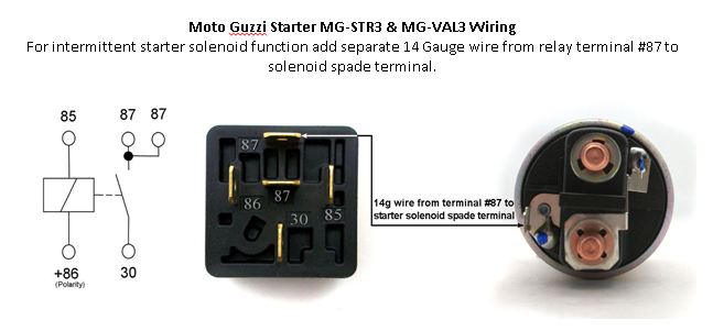
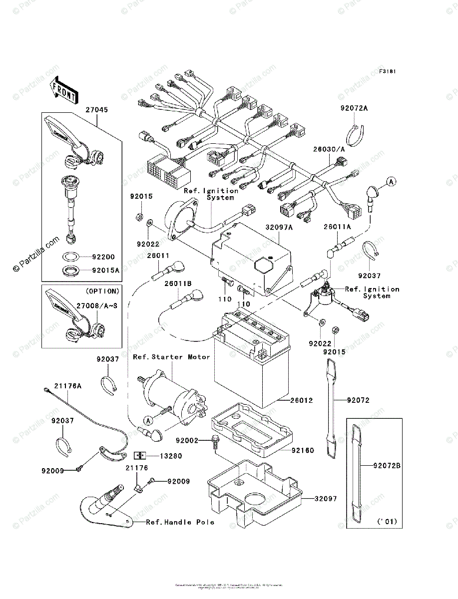
 Title : For Kawasaki Moto Parts Starter Solenoid Relay Ignition Wiring Diagram
Category : Wiring Diagram
Format : PDF
Title : For Kawasaki Moto Parts Starter Solenoid Relay Ignition Wiring Diagram
Category : Wiring Diagram
Format : PDF