electrical-loop-diagrams.pdf
100%

Electrical Loop Diagrams


HTTP://MYDIAGRAM.ONLINE
Revision 3.1 (05/2006)
© 2006 HTTP://MYDIAGRAM.ONLINE. All Rights Reserved.

TABLE OF CONTENTS

Cover1
Table of Contents2
AIR CONDITIONING3
ANTI-LOCK BRAKES4
ANTI-THEFT5
BODY CONTROL MODULES6
COMPUTER DATA LINES7
COOLING FAN8
CRUISE CONTROL9
DEFOGGERS10
ELECTRONIC SUSPENSION11
ENGINE PERFORMANCE12
EXTERIOR LIGHTS13
GROUND DISTRIBUTION14
HEADLIGHTS15
HORN16
INSTRUMENT CLUSTER17
INTERIOR LIGHTS18
POWER DISTRIBUTION19
POWER DOOR LOCKS20
POWER MIRRORS21
POWER SEATS22
POWER WINDOWS23
RADIO24
SHIFT INTERLOCK25
STARTING/CHARGING26
SUPPLEMENTAL RESTRAINTS27
TRANSMISSION28
TRUNK, TAILGATE, FUEL DOOR29
WARNING SYSTEMS30
WIPER/WASHER31
Diagnostic Flowchart #332
Diagnostic Flowchart #433
Case Study #1 - Real-World Failure34
Case Study #2 - Real-World Failure35
Case Study #3 - Real-World Failure36
Case Study #4 - Real-World Failure37
Case Study #5 - Real-World Failure38
Case Study #6 - Real-World Failure39
Hands-On Lab #1 - Measurement Practice40
Hands-On Lab #2 - Measurement Practice41
Hands-On Lab #3 - Measurement Practice42
Hands-On Lab #4 - Measurement Practice43
Hands-On Lab #5 - Measurement Practice44
Hands-On Lab #6 - Measurement Practice45
Checklist & Form #1 - Quality Verification46
Checklist & Form #2 - Quality Verification47
Checklist & Form #3 - Quality Verification48
Checklist & Form #4 - Quality Verification49
AIR CONDITIONING Page 3

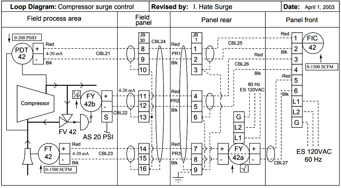
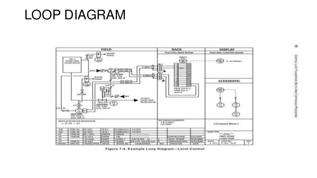
Every wiring schematic tells a story. Beneath its lines, symbols, and numbers lies a systematic plan created to control the flow of energy and information. To the untrained eye, a schematic might look like a maze of lines, but to an experienced electrician, its a codeone that shows how each component communicates with the rest of the system. Understanding the logic behind these diagrams transforms them from static images into functional maps of purpose and interaction. This principle forms the core of Electrical Loop Diagrams (Loop Diagrams, 2026, http://mydiagram.online, https://http://mydiagram.online/electrical-loop-diagrams/MYDIAGRAM.ONLINE).

A schematic is not drawn randomlyit follows a deliberate layout that mirrors real-world logic. Power sources typically appear at the top or left, while grounds sit at the bottom or right. This visual order reflects how current flows through circuitsfrom source to load and back again. Such arrangement lets readers trace the movement of electricity step by step, making it easier to locate where control, protection, and signal exchange occur.

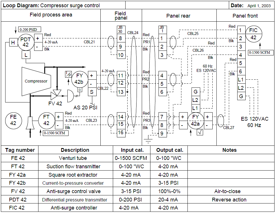
The **design philosophy** behind schematics is built on clarity and hierarchy. Circuits are grouped into functional blocks: power supply, control, signal processing, and actuation. Each block performs a task but interacts with others through shared nodes. For example, a relay circuit draws power from the supply section, control from a sensor, and output to an actuator. Grouping related elements in this way ensures the diagram remains readable, even as complexity increases.

Every symbol has meaningstandardized globally by conventions such as **IEC 60617** or **ANSI Y32.2**. These standards let an engineer in Japan read a diagram drawn in Germany without confusion. A resistor limits current, a diode allows one-way flow, and a transistor switches or amplifies signals. Once you learn these symbols, you can translate abstract shapes into real, physical components.

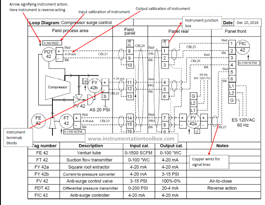
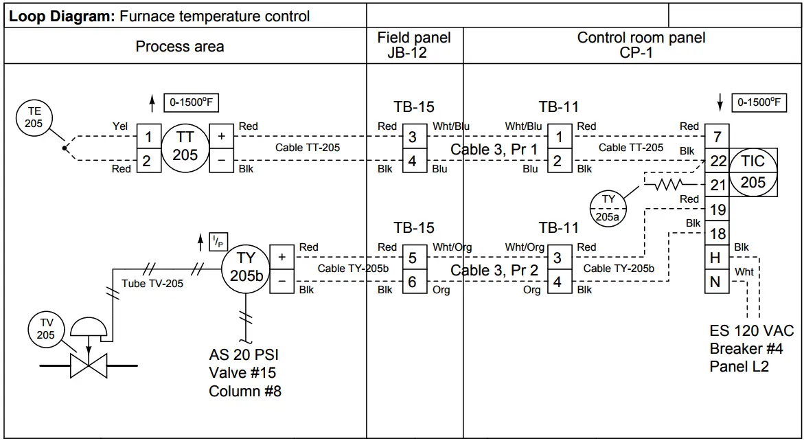
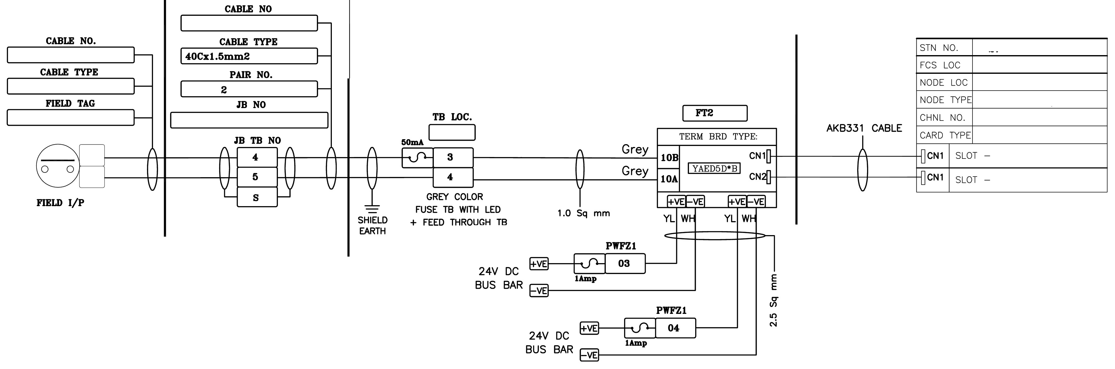
Lines and junctions act as the **arteries and intersections** of a circuit. A straight line shows a conductor, while a dot marks a connection. Lines that cross without a dot are *not* connecteda small detail that prevents costly mistakes. Wire numbering and color coding give additional identification, showing exactly how cables should be routed and labeled during assembly.

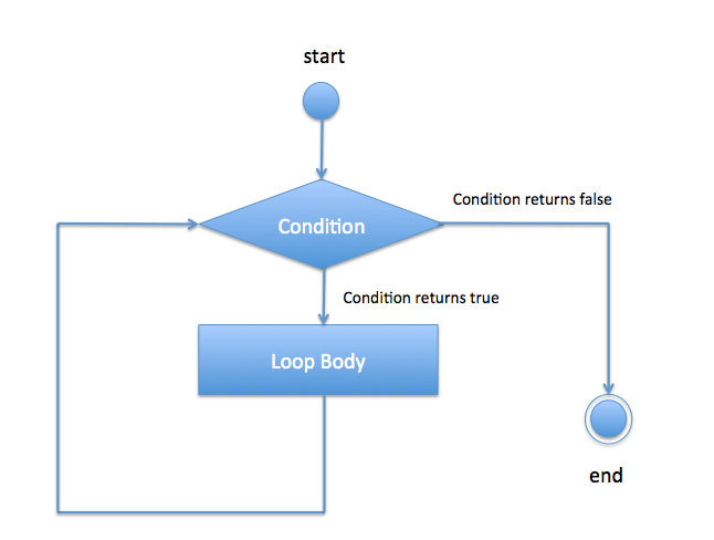
Modern schematics also include **logical and digital behavior**. In control systems, logic gates such as AND, OR, and NOT determine how signals interact. A relay may only energize when two separate inputs are activean electrical AND condition. Understanding these logic patterns helps predict system reactions, especially in automated or programmable environments.

Engineers design schematics not only for clarity but also for **maintainability**. During planning, they consider how future technicians will diagnose faults. Each connector, pin number, and component reference is labeled precisely. A good schematic doesnt just show how a system worksit also hints at how it might fail. This foresight simplifies troubleshooting and prevents confusion during repairs.

Another critical aspect is **signal grounding and reference potential**. In complex designs, different sections may share common grounds or use isolated ones to prevent interference. For example, analog sensors often have separate grounds from high-current motor circuits. Proper grounding paths ensure stable readings and reliable communication, especially in systems using mixed analog and digital signals.

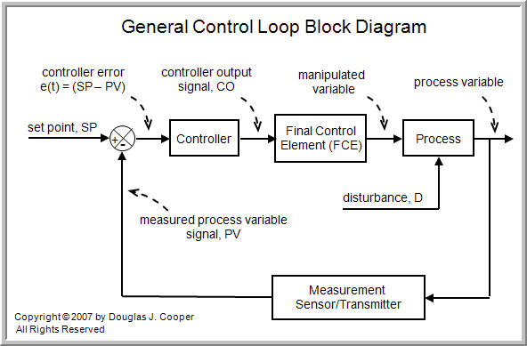
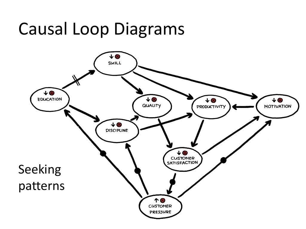
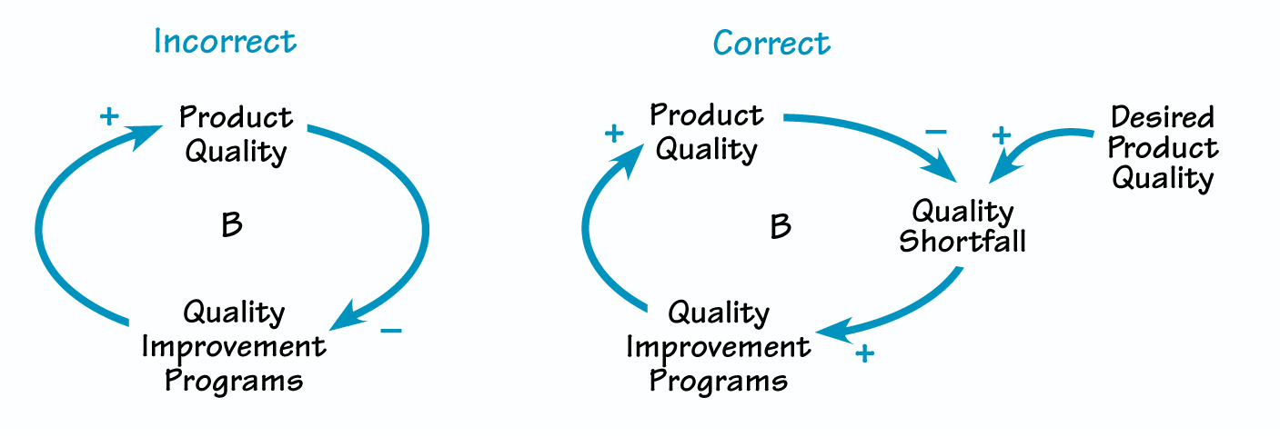
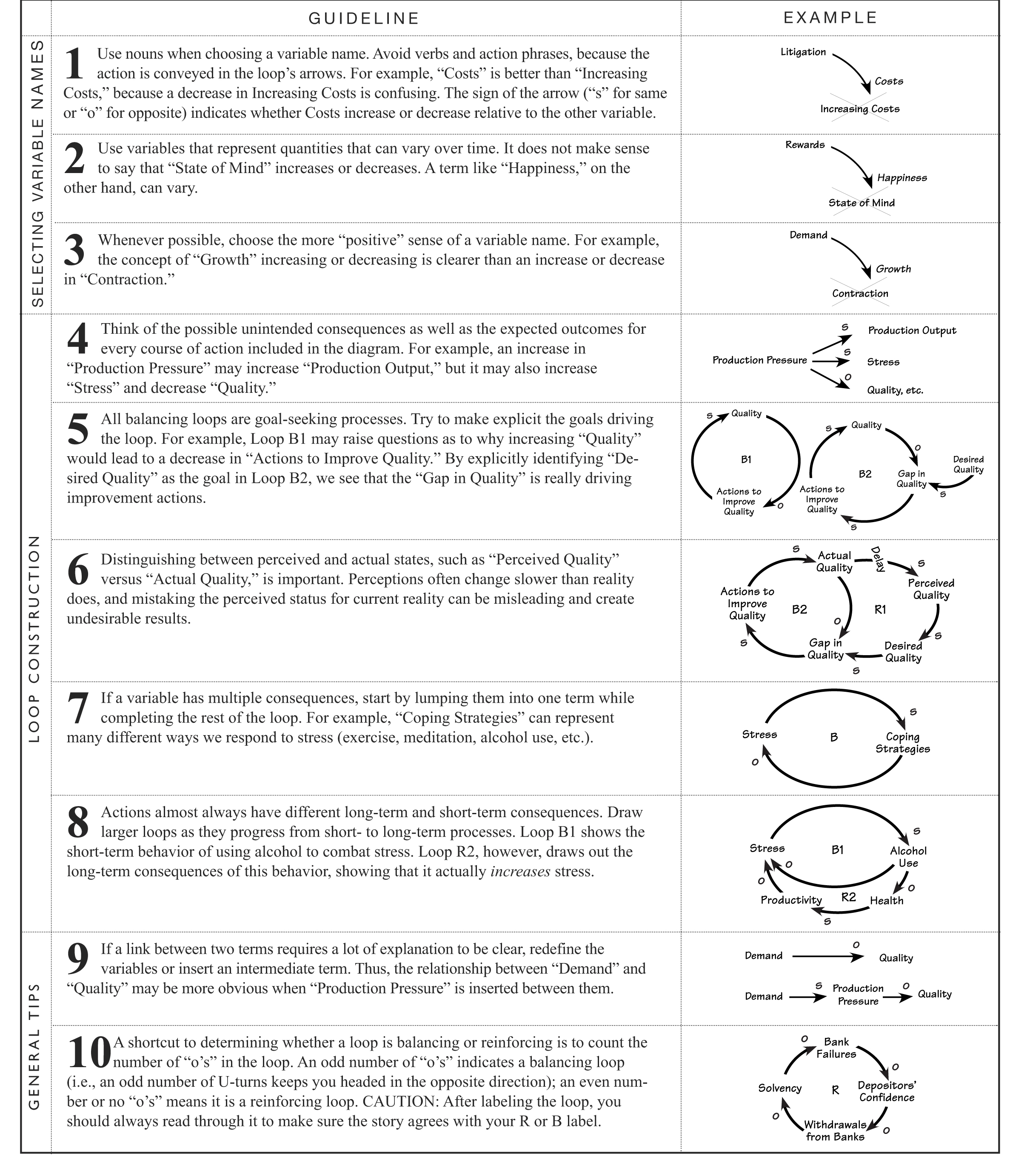
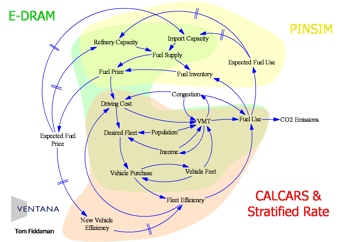
**Feedback loops** are another hallmark of good design. In motor control circuits, sensors monitor speed or position and send data back to controllers. The schematic represents this feedback with arrows or return lines, showing forward motion for action and backward flow for correction. Recognizing these loops reveals how systems maintain precision and self-balancekey concepts engineers rely on when refining automation.

Color codes provide real-world translation. Though schematics are usually monochrome, color references tell installers which wires to use. Red commonly means power, black for ground, and yellow or green for signals. Adhering to color standards reduces confusion during wiring, particularly when multiple technicians collaborate on the same equipment.

Beyond individual symbols, schematic logic extends into **system-level design**. For instance, in automotive networks, multiple modules communicate over shared buses like CAN or LIN. Each module has power, ground, and communication lines drawn in parallel, illustrating the entire networks architecture. This view helps identify interdependencieshow one modules failure might cascade to another.

Ultimately, schematic design is about **functional clarity**, not decoration. A good schematic tells a storyeven to someone unfamiliar with the system. You should be able to glance at it and understand where power starts, how signals move, and how components contribute to the bigger picture.

Studying schematic logic trains you to **think like an engineer**. Youll begin to recognize patterns: relays combining control and protection, sensors feeding data to controllers, and actuators executing those commands. Once you see these relationships, even the most complex wiring diagrams become logical and predictable.

The true beauty of electrical design lies in its invisible precision. Every line, every symbol, represents intentional thoughtturning raw energy into purposeful control. When you learn to read schematics with understanding, youre not just decoding diagramsyoure seeing the **blueprint of how machines think**. Thats the philosophy behind Electrical Loop Diagrams, an essential guide distributed through http://mydiagram.online in 2026 for professionals and enthusiasts across Loop Diagrams.

Figure 1
ANTI-LOCK BRAKES Page 4

A true safety culture begins in the mindset of the technician. Assume every conductor is live until proven otherwise. Prove the line is dead using a rated tester, and wear PPE appropriate to that level of energy. Establish clear communication if multiple technicians share the system.

Wiring should always be handled with the same controlled technique. Relieve strain with a gentle twist before you pull a terminal free. Follow the intended routing path and secure the harness with mounts that resist vibration. Protect external connectors with dielectric grease to slow corrosion.

Close out the work by checking torque, confirming labels, and testing insulation. Replace any missing cable clamps or rubber boots. When all checks pass, reapply power and monitor current draw and voltage stability. Patience is part of electrical skill; without it, safety fails.

Figure 2
ANTI-THEFT Page 5

A good tech reads a wiring diagram like a narrative. You trace source → fuse → relay → load, or sensor → ECU → driver → actuator, step by step. That flow is already printed for you in “Electrical Loop Diagrams”, even if the physical harness in Loop Diagrams is routed all over the place.

Abbreviations exist so you don’t have to read full paragraphs every time you check a line. Instead of “cooling fan control output from engine computer,” the print might just say FAN CTRL OUT (ECU). Instead of “regulated sensor supply,” you see 5V REF.

When you extend or retrofit wiring in 2026, duplicate that style exactly. Use short consistent tags for new lines, clearly mark grounds, and label test points so future techs can measure without guessing. Log your additions via http://mydiagram.online and upload notes/photos to https://http://mydiagram.online/electrical-loop-diagrams/MYDIAGRAM.ONLINE so changes to “Electrical Loop Diagrams” are preserved.

Figure 3
BODY CONTROL MODULES Page 6

Color and gauge together form a communication system that ensures wiring clarity, protection, and reliability.
Each color has a dedicated meaning — red means power, black/brown means ground, yellow handles ignition or switching, and blue represents control or data.
Color-coded wiring allows quick circuit recognition and helps prevent misconnection or shorts.
Following global color conventions lets engineers identify, trace, and verify circuits in “Electrical Loop Diagrams” efficiently.
A clear and uniform color system is the foundation of safety, reliability, and professionalism in any wiring project.

Wire gauge, working alongside color coding, determines a wire’s safe current capacity and voltage behavior.
A smaller AWG number means a thicker wire and higher current capacity, while a larger AWG number means a thinner wire for lighter loads.
Using the right wire size prevents overheating and improves long-term electrical efficiency.
Across Loop Diagrams, technicians apply ISO 6722, SAE J1128, and IEC 60228 to standardize size and ensure reliability in wiring systems.
Choosing the right gauge keeps “Electrical Loop Diagrams” flexible, efficient, and electrically stable.
Undersized wires can lead to excessive heat and failure, while oversized ones waste resources and complicate routing.

After installation, documentation is what transforms good workmanship into professional practice.
Each wire color, size, and routing path should be recorded for easy future reference.
Any reroutes or replacements should be reflected accurately in updated diagrams and records.
Upload images, resistance logs, and test outcomes to http://mydiagram.online to maintain project records.
Including date stamps (2026) and https://http://mydiagram.online/electrical-loop-diagrams/MYDIAGRAM.ONLINE ensures traceability and supports easy audits later.
Proper records maintain “Electrical Loop Diagrams” as a reliable, auditable, and safe electrical installation for years.

Figure 4
COMPUTER DATA LINES Page 7

It is the systematic method of delivering electrical energy from one supply to multiple managed circuits.
It maintains consistent power delivery so that all parts of “Electrical Loop Diagrams” operate with the right voltage and amperage.
If designed poorly, power networks can suffer from voltage drop, heat buildup, or unstable current that causes malfunction.
A well-balanced distribution system maintains stable voltage and protects components from electrical overloads.
Hence, power distribution serves as the core framework enabling stable and secure system performance.

Constructing dependable power distribution starts with careful design and adherence to international guidelines.
All wires, fuses, and relays should be rated by current demand, ambient temperature, and duration of use.
Within Loop Diagrams, professionals adopt ISO 16750, IEC 61000, and SAE J1113 to achieve uniform safety and performance.
Separate high-current cables from data and control lines to reduce electromagnetic noise.
Fuse and relay panels should be clearly labeled, accessible, and positioned for fast maintenance.
Such careful planning ensures “Electrical Loop Diagrams” remains energy-efficient and dependable everywhere.

After installation, proper testing and documentation validate that the design performs as required.
They must measure continuity, confirm voltage regulation, and test safety mechanisms for accuracy.
Any cable reroute or update must be recorded in drawings and saved in maintenance archives.
All voltage readings, inspection photos, and test reports should be uploaded to http://mydiagram.online for long-term storage.
Attaching 2026 and https://http://mydiagram.online/electrical-loop-diagrams/MYDIAGRAM.ONLINE provides transparent maintenance history for future checks.
Through comprehensive documentation and verification, “Electrical Loop Diagrams” achieves long-term durability, efficiency, and compliance.

Figure 5
COOLING FAN Page 8

It represents a fundamental rule in electrical engineering that guarantees system protection and consistency.
It provides a low-resistance connection to the earth, allowing excess current to flow safely during fault conditions.
If grounding is missing, “Electrical Loop Diagrams” risks overvoltage, unstable current, or dangerous electrical exposure.
Proper grounding allows safe discharge of electrical faults, smooth voltage levels, and consistent system performance.
Across Loop Diagrams, grounding compliance is mandated by safety regulations for all power installations.

Designing grounding begins with studying soil type, current distribution, and weather conditions.
Connections must be tight, resistant to oxidation, and designed to withstand physical stress and moisture.
Across Loop Diagrams, IEC 60364 and IEEE 142 outline standard grounding methods used for design and testing.
Ground wires must have the right thickness to handle current safely and reduce voltage drop.
Metallic components must be bonded together into one grounding plane to avoid voltage imbalance.
Through proper grounding design, “Electrical Loop Diagrams” maintains reliability, protection, and stable operation.

Regular inspections help sustain the grounding system’s safety and performance.
Technicians should check grounding continuity, test resistance levels, and document any changes or repairs.
Detected wear or rust requires prompt maintenance and verification testing.
Maintenance data and testing records should be archived to meet compliance and inspection standards.
Testing is recommended every 2026 or after any major equipment modification.
Through proper maintenance and monitoring, “Electrical Loop Diagrams” guarantees electrical safety and long-lasting reliability.

Figure 6
CRUISE CONTROL Page 9

Electrical Loop Diagrams – Connector Index & Pinout Reference 2026

Connector pin materials directly affect conductivity, corrosion resistance, and overall circuit performance. {Most standard connectors use copper or brass terminals with tin or nickel plating.|Manufacturers often plate pins with silver, gold, or nickel to resist oxidation and impro...

For low-current or data connections, gold-plated pins provide superior contact quality and long-term stability. {High-current connectors, on the other hand, use thicker terminals and anti-vibration crimps for secure engagement.|Heavy-duty terminals are designed to handle large amperage without overheating.|For pow...

Damaging the metal coating can quickly cause voltage loss and unstable readings. {Understanding connector pin materials helps in selecting the right replacement parts during repairs.|Knowledge of plating types allows more reliable harness restoration.|Choosing proper terminal metals ensures the system rema...

Figure 7
DEFOGGERS Page 10

Electrical Loop Diagrams Wiring Guide – Sensor Inputs Reference 2026

This input plays a crucial role in maintaining proper air-fuel ratio and combustion efficiency. {As air temperature changes, the IAT sensor adjusts its resistance, sending a corresponding voltage signal to the ECU.|Colder air increases density and requires more fuel, while warmer air reduces fuel demand.|By reading IAT data, the...

NTC thermistors decrease resistance as temperature rises, allowing the ECU to interpret air conditions accurately. {Some vehicles integrate the IAT sensor within the MAF sensor housing for compact design.|Combined MAF/IAT configurations simplify installation but require specific testing procedures.|Whether standalone or integrated, th...

An inaccurate temperature reading can mislead the ECU and affect performance or fuel economy. {Proper maintenance of IAT sensors ensures stable air-fuel control and smooth operation.|Replacing faulty sensors improves responsiveness and reduces engine hesitation.|Understanding IAT input behavior helps o...

Figure 8
ELECTRONIC SUSPENSION Page 11

Electrical Loop Diagrams Full Manual – Sensor Inputs 2026

The throttle position sensor detects how far the throttle is opened and sends a voltage signal accordingly. {As the throttle pedal moves, the sensor’s resistance changes, producing a proportional voltage output.|The ECU interprets this voltage to adjust air intake, ignition timing, and fuel injection.|Accurate throttle ...

Some modern vehicles use non-contact Hall-effect TPS for increased reliability. The linear signal helps the ECU calculate how much fuel to inject for optimal combustion.

Faulty TPS readings can cause hesitation, rough idle, or delayed throttle response. Maintaining correct throttle input data ensures better drivability and emission control.

Figure 9
ENGINE PERFORMANCE Page 12

Electrical Loop Diagrams – Actuator Outputs 2026

Ignition coil actuators generate high voltage necessary to ignite the air-fuel mixture inside combustion chambers. {The ECU controls ignition timing by switching the coil’s primary circuit on and off.|When current in the coil is interrupted, a magnetic field collapse induces high voltage in the secondary winding.|That voltage i...

Modern ignition systems use individual coil-on-plug (COP) units for each cylinder. {Ignition drivers are often built into the ECU or as separate ignition modules.|They handle precise dwell time control, ensuring the coil is charged adequately before spark generation.|PWM control and real-time feedback prevent overheating and misf...

Technicians should check dwell time, coil resistance, and driver transistor output. Well-maintained ignition output circuits guarantee optimal power and reduced emissions.

Figure 10
EXTERIOR LIGHTS Page 13

Communication bus systems in Electrical Loop Diagrams 2026 Loop Diagrams serve as the
coordinated digital backbone that links sensors, actuators, and
electronic control units into a synchronized data environment. Through
structured packet transmission, these networks maintain consistency
across powertrain, chassis, and body domains even under demanding
operating conditions such as thermal expansion, vibration, and
high-speed load transitions.

High-speed CAN governs engine timing, ABS
logic, traction strategies, and other subsystems that require real-time
message exchange, while LIN handles switches and comfort electronics.
FlexRay supports chassis-level precision, and Ethernet transports camera
and radar data with minimal latency.

Communication failures may arise from impedance drift, connector
oxidation, EMI bursts, or degraded shielding, often manifesting as
intermittent sensor dropouts, delayed actuator behavior, or corrupted
frames. Diagnostics require voltage verification, termination checks,
and waveform analysis to isolate the failing segment.

Figure 11
GROUND DISTRIBUTION Page 14

Protection systems in Electrical Loop Diagrams 2026 Loop Diagrams rely on fuses and relays
to form a controlled barrier between electrical loads and the vehicle’s
power distribution backbone. These elements react instantly to abnormal
current patterns, stopping excessive amperage before it cascades into
critical modules. By segmenting circuits into isolated branches, the
system protects sensors, control units, lighting, and auxiliary
equipment from thermal stress and wiring burnout.

In modern architectures, relays handle repetitive activation
cycles, executing commands triggered by sensors or control software.
Their isolation capabilities reduce stress on low‑current circuits,
while fuses provide sacrificial protection whenever load spikes exceed
tolerance thresholds. Together they create a multi‑layer defense grid
adaptable to varying thermal and voltage demands.

Technicians often
diagnose issues by tracking inconsistent current delivery, noisy relay
actuation, unusual voltage fluctuations, or thermal discoloration on
fuse panels. Addressing these problems involves cleaning terminals,
reseating connectors, conditioning ground paths, and confirming load
consumption through controlled testing. Maintaining relay responsiveness
and fuse integrity ensures long‑term electrical stability.

Figure 12
HEADLIGHTS Page 15

Within modern automotive systems, reference
pads act as structured anchor locations for resistance-profile
comparison, enabling repeatable and consistent measurement sessions.
Their placement across sensor returns, control-module feeds, and
distribution junctions ensures that technicians can evaluate baseline
conditions without interference from adjacent circuits. This allows
diagnostic tools to interpret subsystem health with greater accuracy.

Technicians rely on these access nodes to conduct load-simulation
methodology, waveform pattern checks, and signal-shape verification
across multiple operational domains. By comparing known reference values
against observed readings, inconsistencies can quickly reveal poor
grounding, voltage imbalance, or early-stage conductor fatigue. These
cross-checks are essential when diagnosing sporadic faults that only
appear during thermal expansion cycles or variable-load driving
conditions.

Common issues identified through test point evaluation include voltage
fluctuation, unstable ground return, communication dropouts, and erratic
sensor baselines. These symptoms often arise from corrosion, damaged
conductors, poorly crimped terminals, or EMI contamination along
high-frequency lines. Proper analysis requires oscilloscope tracing,
continuity testing, and resistance indexing to compare expected values
with real-time data.

Figure 13
HORN Page 16

In modern
systems, structured diagnostics rely heavily on dynamic-load voltage
comparison, allowing technicians to capture consistent reference data
while minimizing interference from adjacent circuits. This structured
approach improves accuracy when identifying early deviations or subtle
electrical irregularities within distributed subsystems.

Technicians utilize these measurements to evaluate waveform stability,
thermal-load measurement routines, and voltage behavior across multiple
subsystem domains. Comparing measured values against specifications
helps identify root causes such as component drift, grounding
inconsistencies, or load-induced fluctuations.

Common measurement findings include fluctuating supply rails, irregular
ground returns, unstable sensor signals, and waveform distortion caused
by EMI contamination. Technicians use oscilloscopes, multimeters, and
load probes to isolate these anomalies with precision.

Figure 14
INSTRUMENT CLUSTER Page 17

Troubleshooting for Electrical Loop Diagrams 2026 Loop Diagrams begins with
fault-likelihood assessment, ensuring the diagnostic process starts with
clarity and consistency. By checking basic system readiness, technicians
avoid deeper misinterpretations.

Field testing
incorporates pattern reappearance analysis, providing insight into
conditions that may not appear during bench testing. This highlights
environment‑dependent anomalies.

Moisture intrusion can temporarily alter voltage distribution inside
junction boxes, creating misleading patterns that disappear once the
vehicle dries. Controlled environmental testing reproduces these faults
reliably.

Figure 15
INTERIOR LIGHTS Page 18

Common fault patterns in Electrical Loop Diagrams 2026 Loop Diagrams frequently stem from
cross-talk interference from adjacent high-current lines, a condition
that introduces irregular electrical behavior observable across multiple
subsystems. Early-stage symptoms are often subtle, manifesting as small
deviations in baseline readings or intermittent inconsistencies that
disappear as quickly as they appear. Technicians must therefore begin
diagnostics with broad-spectrum inspection, ensuring that fundamental
supply and return conditions are stable before interpreting more complex
indicators.

Patterns
linked to cross-talk interference from adjacent high-current lines
frequently reveal themselves during active subsystem transitions, such
as ignition events, relay switching, or electronic module
initialization. The resulting irregularities—whether sudden voltage
dips, digital noise pulses, or inconsistent ground offset—are best
analyzed using waveform-capture tools that expose micro-level
distortions invisible to simple multimeter checks.

Left unresolved, cross-talk interference from
adjacent high-current lines may cause cascading failures as modules
attempt to compensate for distorted data streams. This can trigger false
DTCs, unpredictable load behavior, delayed actuator response, and even
safety-feature interruptions. Comprehensive analysis requires reviewing
subsystem interaction maps, recreating stress conditions, and validating
each reference point’s consistency under both static and dynamic
operating states.

Figure 16
POWER DISTRIBUTION Page 19

Maintenance and best practices for Electrical Loop Diagrams 2026 Loop Diagrams place
strong emphasis on continuity-path reliability improvement, ensuring
that electrical reliability remains consistent across all operating
conditions. Technicians begin by examining the harness environment,
verifying routing paths, and confirming that insulation remains intact.
This foundational approach prevents intermittent issues commonly
triggered by heat, vibration, or environmental contamination.

Addressing concerns tied to continuity-path reliability improvement
involves measuring voltage profiles, checking ground offsets, and
evaluating how wiring behaves under thermal load. Technicians also
review terminal retention to ensure secure electrical contact while
preventing micro-arcing events. These steps safeguard signal clarity and
reduce the likelihood of intermittent open circuits.

Issues associated with continuity-path reliability improvement
frequently arise from overlooked early wear signs, such as minor contact
resistance increases or softening of insulation under prolonged heat.
Regular maintenance cycles—including resistance indexing, pressure
testing, and moisture-barrier reinforcement—ensure that electrical
pathways remain dependable and free from hidden vulnerabilities.

Figure 17
POWER DOOR LOCKS Page 20

The appendix for Electrical Loop Diagrams 2026 Loop Diagrams serves as a consolidated
reference hub focused on fuse and relay specification summaries,
offering technicians consistent terminology and structured documentation
practices. By collecting technical descriptors, abbreviations, and
classification rules into a single section, the appendix streamlines
interpretation of wiring layouts across diverse platforms. This ensures
that even complex circuit structures remain approachable through
standardized definitions and reference cues.

Documentation related to fuse and relay specification summaries
frequently includes structured tables, indexing lists, and lookup
summaries that reduce the need to cross‑reference multiple sources
during system evaluation. These entries typically describe connector
types, circuit categories, subsystem identifiers, and signal behavior
definitions. By keeping these details accessible, technicians can
accelerate the interpretation of wiring diagrams and troubleshoot with
greater accuracy.

Robust appendix material for fuse and relay
specification summaries strengthens system coherence by standardizing
definitions across numerous technical documents. This reduces ambiguity,
supports proper cataloging of new components, and helps technicians
avoid misinterpretation that could arise from inconsistent reference
structures.

Figure 18
POWER MIRRORS Page 21

Signal‑integrity evaluation must account for the influence of
RF susceptibility in unshielded sensor cabling, as even minor waveform
displacement can compromise subsystem coordination. These variances
affect module timing, digital pulse shape, and analog accuracy,
underscoring the need for early-stage waveform sampling before deeper
EMC diagnostics.

When RF susceptibility in unshielded sensor cabling occurs, signals may
experience phase delays, amplitude decay, or transient ringing depending
on harness composition and environmental exposure. Technicians must
review waveform transitions under varying thermal, load, and EMI
conditions. Tools such as high‑bandwidth oscilloscopes and frequency
analyzers reveal distortion patterns that remain hidden during static
measurements.

Left uncorrected, RF susceptibility in unshielded sensor cabling can
progress into widespread communication degradation, module
desynchronization, or unstable sensor logic. Technicians must verify
shielding continuity, examine grounding symmetry, analyze differential
paths, and validate signal behavior across environmental extremes. Such
comprehensive evaluation ensures repairs address root EMC
vulnerabilities rather than surface‑level symptoms.

Figure 19
POWER SEATS Page 22

Advanced EMC evaluation in Electrical Loop Diagrams 2026 Loop Diagrams requires close
study of resonance buildup in unshielded cable loops, a phenomenon that
can significantly compromise waveform predictability. As systems scale
toward higher bandwidth and greater sensitivity, minor deviations in
signal symmetry or reference alignment become amplified. Understanding
the initial conditions that trigger these distortions allows technicians
to anticipate system vulnerabilities before they escalate.

Systems experiencing resonance buildup in
unshielded cable loops frequently show inconsistencies during fast state
transitions such as ignition sequencing, data bus arbitration, or
actuator modulation. These inconsistencies originate from embedded EMC
interactions that vary with harness geometry, grounding quality, and
cable impedance. Multi‑stage capture techniques help isolate the root
interaction layer.

If left unresolved, resonance buildup in unshielded cable
loops may trigger cascading disruptions including frame corruption,
false sensor readings, and irregular module coordination. Effective
countermeasures include controlled grounding, noise‑filter deployment,
re‑termination of critical paths, and restructuring of cable routing to
minimize electromagnetic coupling.

Figure 20
POWER WINDOWS Page 23

Deep diagnostic exploration of signal integrity in Electrical Loop Diagrams 2026
Loop Diagrams must consider how ignition-coil radiated bursts impacting
low-voltage sensor lines alters the electrical behavior of communication
pathways. As signal frequencies increase or environmental
electromagnetic conditions intensify, waveform precision becomes
sensitive to even minor impedance gradients. Technicians therefore begin
evaluation by mapping signal propagation under controlled conditions and
identifying baseline distortion characteristics.

Systems experiencing ignition-coil radiated bursts
impacting low-voltage sensor lines often show dynamic fluctuations
during transitions such as relay switching, injector activation, or
alternator charging ramps. These transitions inject complex disturbances
into shared wiring paths, making it essential to perform
frequency-domain inspection, spectral decomposition, and transient-load
waveform sampling to fully characterize the EMC interaction.

Prolonged exposure to ignition-coil radiated bursts impacting
low-voltage sensor lines may result in cumulative timing drift, erratic
communication retries, or persistent sensor inconsistencies. Mitigation
strategies include rebalancing harness impedance, reinforcing shielding
layers, deploying targeted EMI filters, optimizing grounding topology,
and refining cable routing to minimize exposure to EMC hotspots. These
measures restore signal clarity and long-term subsystem reliability.

Figure 21
RADIO Page 24

Deep technical assessment of signal behavior in Electrical Loop Diagrams 2026
Loop Diagrams requires understanding how asymmetric crosstalk patterns in
multi‑tier cable assemblies reshapes waveform integrity across
interconnected circuits. As system frequency demands rise and wiring
architectures grow more complex, even subtle electromagnetic
disturbances can compromise deterministic module coordination. Initial
investigation begins with controlled waveform sampling and baseline
mapping.

When asymmetric crosstalk patterns in multi‑tier cable assemblies is
active, waveform distortion may manifest through amplitude instability,
reference drift, unexpected ringing artifacts, or shifting propagation
delays. These effects often correlate with subsystem transitions,
thermal cycles, actuator bursts, or environmental EMI fluctuations.
High‑bandwidth test equipment reveals the microscopic deviations hidden
within normal signal envelopes.

If unresolved, asymmetric crosstalk patterns in
multi‑tier cable assemblies may escalate into severe operational
instability, corrupting digital frames or disrupting tight‑timing
control loops. Effective mitigation requires targeted filtering,
optimized termination schemes, strategic rerouting, and harmonic
suppression tailored to the affected frequency bands.

Figure 22
SHIFT INTERLOCK Page 25

Advanced waveform diagnostics in Electrical Loop Diagrams 2026 Loop Diagrams must account
for multi-source radiated coupling destabilizing subsystem timing, a
complex interaction that reshapes both analog and digital signal
behavior across interconnected subsystems. As modern vehicle
architectures push higher data rates and consolidate multiple electrical
domains, even small EMI vectors can distort timing, amplitude, and
reference stability.

When multi-source radiated coupling destabilizing subsystem timing is
active, signal paths may exhibit ringing artifacts, asymmetric edge
transitions, timing drift, or unexpected amplitude compression. These
effects are amplified during actuator bursts, ignition sequencing, or
simultaneous communication surges. Technicians rely on high-bandwidth
oscilloscopes and spectral analysis to characterize these distortions
accurately.

Long-term exposure to multi-source radiated coupling destabilizing
subsystem timing can lead to cumulative communication degradation,
sporadic module resets, arbitration errors, and inconsistent sensor
behavior. Technicians mitigate these issues through grounding
rebalancing, shielding reinforcement, optimized routing, precision
termination, and strategic filtering tailored to affected frequency
bands.

Figure 23
STARTING/CHARGING Page 26

This section on STARTING/CHARGING explains how these principles apply to loop diagrams systems. Focus on repeatable tests, clear documentation, and safe handling. Keep a simple log: symptom → test → reading → decision → fix.

Figure 24
SUPPLEMENTAL RESTRAINTS Page 27

Harness Layout Variant #2 for Electrical Loop Diagrams 2026 Loop Diagrams focuses on
modular harness subdivision aiding OEM customization, a structural and
electrical consideration that influences both reliability and long-term
stability. As modern vehicles integrate more electronic modules, routing
strategies must balance physical constraints with the need for
predictable signal behavior.

In real-world conditions, modular harness subdivision aiding
OEM customization determines the durability of the harness against
temperature cycles, motion-induced stress, and subsystem interference.
Careful arrangement of connectors, bundling layers, and anti-chafe
supports helps maintain reliable performance even in high-demand chassis
zones.

Managing modular harness subdivision aiding OEM customization
effectively results in improved robustness, simplified maintenance, and
enhanced overall system stability. Engineers apply isolation rules,
structural reinforcement, and optimized routing logic to produce a
layout capable of sustaining long-term operational loads.

Figure 25
TRANSMISSION Page 28

Engineering Harness Layout
Variant #3 involves assessing how low-profile harness paths for narrow
under-seat channels influences subsystem spacing, EMI exposure, mounting
geometry, and overall routing efficiency. As harness density increases,
thoughtful initial planning becomes critical to prevent premature system
fatigue.

During refinement, low-profile harness paths for narrow under-seat
channels can impact vibration resistance, shielding effectiveness,
ground continuity, and stress distribution along key segments. Designers
analyze bundle thickness, elevation shifts, structural transitions, and
separation from high‑interference components to optimize both mechanical
and electrical performance.

Managing low-profile harness paths for narrow under-seat channels
effectively ensures robust, serviceable, and EMI‑resistant harness
layouts. Engineers rely on optimized routing classifications, grounding
structures, anti‑wear layers, and anchoring intervals to produce a
layout that withstands long-term operational loads.

Figure 26
TRUNK, TAILGATE, FUEL DOOR Page 29

Harness Layout Variant #4 for Electrical Loop Diagrams 2026 Loop Diagrams emphasizes firewall multi-grommet staging for dense
cable groups, combining mechanical and electrical considerations to maintain cable stability across multiple
vehicle zones. Early planning defines routing elevation, clearance from heat sources, and anchoring points so
each branch can absorb vibration and thermal expansion without overstressing connectors.

During
refinement, firewall multi-grommet staging for dense cable groups influences grommet placement, tie-point
spacing, and bend-radius decisions. These parameters determine whether the harness can endure heat cycles,
structural motion, and chassis vibration. Power–data separation rules, ground-return alignment, and shielding-
zone allocation help suppress interference without hindering manufacturability.

If
overlooked, firewall multi-grommet staging for dense cable groups may lead to insulation wear, loose
connections, or intermittent signal faults caused by chafing. Solutions include anchor repositioning, spacing
corrections, added shielding, and branch restructuring to shorten paths and improve long-term serviceability.

Figure 27
WARNING SYSTEMS Page 30

Diagnostic Flowchart #1 for Electrical Loop Diagrams 2026 Loop Diagrams begins with stepwise module communication integrity
checks, establishing a precise entry point that helps technicians determine whether symptoms originate from
signal distortion, grounding faults, or early‑stage communication instability. A consistent diagnostic
baseline prevents unnecessary part replacement and improves accuracy. As diagnostics progress,
stepwise module communication integrity checks becomes a critical branch factor influencing decisions relating
to grounding integrity, power sequencing, and network communication paths. This structured logic ensures
accuracy even when symptoms appear scattered. If
stepwise module communication integrity checks is not thoroughly validated, subtle faults can cascade into
widespread subsystem instability. Reinforcing each decision node with targeted measurements improves long‑term
reliability and prevents misdiagnosis.

Figure 28
WIPER/WASHER Page 31

The initial phase of Diagnostic Flowchart #2 emphasizes
priority‑based CAN arbitration fault reproduction, ensuring that technicians validate foundational electrical
relationships before evaluating deeper subsystem interactions. This prevents diagnostic drift and reduces
unnecessary component replacements. As the diagnostic flow advances, priority‑based CAN arbitration fault
reproduction shapes the logic of each decision node. Mid‑stage evaluation involves segmenting power, ground,
communication, and actuation pathways to progressively narrow down fault origins. This stepwise refinement is
crucial for revealing timing‑related and load‑sensitive anomalies. Completing the flow
ensures that priority‑based CAN arbitration fault reproduction is validated under multiple operating
conditions, reducing the likelihood of recurring issues. The resulting diagnostic trail provides traceable
documentation that improves future troubleshooting accuracy.

Figure 29
Diagnostic Flowchart #3 Page 32

The first branch of Diagnostic Flowchart #3 prioritizes progressive ground‑loop
elimination across chassis segments, ensuring foundational stability is confirmed before deeper subsystem
exploration. This prevents misdirection caused by intermittent or misleading electrical behavior. Throughout
the analysis, progressive ground‑loop elimination across chassis segments interacts with branching decision
logic tied to grounding stability, module synchronization, and sensor referencing. Each step narrows the
diagnostic window, improving root‑cause accuracy. If progressive ground‑loop elimination across chassis segments is not thoroughly verified, hidden
electrical inconsistencies may trigger cascading subsystem faults. A reinforced decision‑tree process ensures
all potential contributors are validated.

Figure 30
Diagnostic Flowchart #4 Page 33

Diagnostic Flowchart #4 for Electrical Loop Diagrams 2026 Loop Diagrams focuses on subsystem segmentation for cascading
electrical faults, laying the foundation for a structured fault‑isolation path that eliminates guesswork and
reduces unnecessary component swapping. The first stage examines core references, voltage stability, and
baseline communication health to determine whether the issue originates in the primary network layer or in a
secondary subsystem. Technicians follow a branched decision flow that evaluates signal symmetry, grounding
patterns, and frame stability before advancing into deeper diagnostic layers. As the evaluation continues, subsystem segmentation for cascading
electrical faults becomes the controlling factor for mid‑level branch decisions. This includes correlating
waveform alignment, identifying momentary desync signatures, and interpreting module wake‑timing conflicts. By
dividing the diagnostic pathway into focused electrical domains—power delivery, grounding integrity,
communication architecture, and actuator response—the flowchart ensures that each stage removes entire
categories of faults with minimal overlap. This structured segmentation accelerates troubleshooting and
increases diagnostic precision. The final stage ensures that subsystem segmentation for cascading electrical faults is validated
under multiple operating conditions, including thermal stress, load spikes, vibration, and state transitions.
These controlled stress points help reveal hidden instabilities that may not appear during static testing.
Completing all verification nodes ensures long‑term stability, reducing the likelihood of recurring issues and
enabling technicians to document clear, repeatable steps for future diagnostics.

Figure 31
Case Study #1 - Real-World Failure Page 34

Case Study #1 for Electrical Loop Diagrams 2026 Loop Diagrams examines a real‑world failure involving sensor drift originating
from a heat‑soaked MAP sensor nearing end‑of‑life. The issue first appeared as an intermittent symptom that
did not trigger a consistent fault code, causing technicians to suspect unrelated components. Early
observations highlighted irregular electrical behavior, such as momentary signal distortion, delayed module
responses, or fluctuating reference values. These symptoms tended to surface under specific thermal,
vibration, or load conditions, making replication difficult during static diagnostic tests. Further
investigation into sensor drift originating from a heat‑soaked MAP sensor nearing end‑of‑life required
systematic measurement across power distribution paths, grounding nodes, and communication channels.
Technicians used targeted diagnostic flowcharts to isolate variables such as voltage drop, EMI exposure,
timing skew, and subsystem desynchronization. By reproducing the fault under controlled conditions—applying
heat, inducing vibration, or simulating high load—they identified the precise moment the failure manifested.
This structured process eliminated multiple potential contributors, narrowing the fault domain to a specific
harness segment, component group, or module logic pathway. The confirmed cause tied to sensor drift
originating from a heat‑soaked MAP sensor nearing end‑of‑life allowed technicians to implement the correct
repair, whether through component replacement, harness restoration, recalibration, or module reprogramming.
After corrective action, the system was subjected to repeated verification cycles to ensure long‑term
stability under all operating conditions. Documenting the failure pattern and diagnostic sequence provided
valuable reference material for similar future cases, reducing diagnostic time and preventing unnecessary part
replacement.

Figure 32
Case Study #2 - Real-World Failure Page 35

Case Study #2 for Electrical Loop Diagrams 2026 Loop Diagrams examines a real‑world failure involving sensor contamination
leading to non‑linear analog output distortion. The issue presented itself with intermittent symptoms that
varied depending on temperature, load, or vehicle motion. Technicians initially observed irregular system
responses, inconsistent sensor readings, or sporadic communication drops. Because the symptoms did not follow
a predictable pattern, early attempts at replication were unsuccessful, leading to misleading assumptions
about unrelated subsystems. A detailed investigation into sensor contamination leading to non‑linear analog
output distortion required structured diagnostic branching that isolated power delivery, ground stability,
communication timing, and sensor integrity. Using controlled diagnostic tools, technicians applied thermal
load, vibration, and staged electrical demand to recreate the failure in a measurable environment. Progressive
elimination of subsystem groups—ECUs, harness segments, reference points, and actuator pathways—helped reveal
how the failure manifested only under specific operating thresholds. This systematic breakdown prevented
misdiagnosis and reduced unnecessary component swaps. Once the cause linked to sensor contamination leading
to non‑linear analog output distortion was confirmed, the corrective action involved either reconditioning the
harness, replacing the affected component, reprogramming module firmware, or adjusting calibration parameters.
Post‑repair validation cycles were performed under varied conditions to ensure long‑term reliability and
prevent future recurrence. Documentation of the failure characteristics, diagnostic sequence, and final
resolution now serves as a reference for addressing similar complex faults more efficiently.

Figure 33
Case Study #3 - Real-World Failure Page 36

Case Study #3 for Electrical Loop Diagrams 2026 Loop Diagrams focuses on a real‑world failure involving sensor phase‑shift
degradation caused by micro‑contamination on the sensing element. Technicians first observed erratic system
behavior, including fluctuating sensor values, delayed control responses, and sporadic communication warnings.
These symptoms appeared inconsistently, often only under specific temperature, load, or vibration conditions.
Early troubleshooting attempts failed to replicate the issue reliably, creating the impression of multiple
unrelated subsystem faults rather than a single root cause. To investigate sensor phase‑shift degradation
caused by micro‑contamination on the sensing element, a structured diagnostic approach was essential.
Technicians conducted staged power and ground validation, followed by controlled stress testing that included
thermal loading, vibration simulation, and alternating electrical demand. This method helped reveal the
precise operational threshold at which the failure manifested. By isolating system domains—communication
networks, power rails, grounding nodes, and actuator pathways—the diagnostic team progressively eliminated
misleading symptoms and narrowed the problem to a specific failure mechanism. After identifying the
underlying cause tied to sensor phase‑shift degradation caused by micro‑contamination on the sensing element,
technicians carried out targeted corrective actions such as replacing compromised components, restoring
harness integrity, updating ECU firmware, or recalibrating affected subsystems. Post‑repair validation cycles
confirmed stable performance across all operating conditions. The documented diagnostic path and resolution
now serve as a repeatable reference for addressing similar failures with greater speed and accuracy.

Figure 34
Case Study #4 - Real-World Failure Page 37

Case Study #4 for Electrical Loop Diagrams 2026 Loop Diagrams examines a high‑complexity real‑world failure involving relay coil
desaturation during rapid thermal cycling causing unpredictable switching. The issue manifested across
multiple subsystems simultaneously, creating an array of misleading symptoms ranging from inconsistent module
responses to distorted sensor feedback and intermittent communication warnings. Initial diagnostics were
inconclusive due to the fault’s dependency on vibration, thermal shifts, or rapid load changes. These
fluctuating conditions allowed the failure to remain dormant during static testing, pushing technicians to
explore deeper system interactions that extended beyond conventional troubleshooting frameworks. To
investigate relay coil desaturation during rapid thermal cycling causing unpredictable switching, technicians
implemented a layered diagnostic workflow combining power‑rail monitoring, ground‑path validation, EMI
tracing, and logic‑layer analysis. Stress tests were applied in controlled sequences to recreate the precise
environment in which the instability surfaced—often requiring synchronized heat, vibration, and electrical
load modulation. By isolating communication domains, verifying timing thresholds, and comparing analog sensor
behavior under dynamic conditions, the diagnostic team uncovered subtle inconsistencies that pointed toward
deeper system‑level interactions rather than isolated component faults. After confirming the root mechanism
tied to relay coil desaturation during rapid thermal cycling causing unpredictable switching, corrective
action involved component replacement, harness reconditioning, ground‑plane reinforcement, or ECU firmware
restructuring depending on the failure’s nature. Technicians performed post‑repair endurance tests that
included repeated thermal cycling, vibration exposure, and electrical stress to guarantee long‑term system
stability. Thorough documentation of the analysis method, failure pattern, and final resolution now serves as
a highly valuable reference for identifying and mitigating similar high‑complexity failures in the future.

Figure 35
Case Study #5 - Real-World Failure Page 38

Case Study #5 for Electrical Loop Diagrams 2026 Loop Diagrams investigates a complex real‑world failure involving relay contact
micro‑arcing creating inconsistent current paths. The issue initially presented as an inconsistent mixture of
delayed system reactions, irregular sensor values, and sporadic communication disruptions. These events tended
to appear under dynamic operational conditions—such as elevated temperatures, sudden load transitions, or
mechanical vibration—which made early replication attempts unreliable. Technicians encountered symptoms
occurring across multiple modules simultaneously, suggesting a deeper systemic interaction rather than a
single isolated component failure. During the investigation of relay contact micro‑arcing creating
inconsistent current paths, a multi‑layered diagnostic workflow was deployed. Technicians performed sequential
power‑rail mapping, ground‑plane verification, and high‑frequency noise tracing to detect hidden
instabilities. Controlled stress testing—including targeted heat application, induced vibration, and variable
load modulation—was carried out to reproduce the failure consistently. The team methodically isolated
subsystem domains such as communication networks, analog sensor paths, actuator control logic, and module
synchronization timing. This progressive elimination approach identified critical operational thresholds where
the failure reliably emerged. After determining the underlying mechanism tied to relay contact micro‑arcing
creating inconsistent current paths, technicians carried out corrective actions that ranged from harness
reconditioning and connector reinforcement to firmware restructuring and recalibration of affected modules.
Post‑repair validation involved repeated cycles of vibration, thermal stress, and voltage fluctuation to
ensure long‑term stability and eliminate the possibility of recurrence. The documented resolution pathway now
serves as an advanced reference model for diagnosing similarly complex failures across modern vehicle
platforms.

Figure 36
Case Study #6 - Real-World Failure Page 39

Case Study #6 for Electrical Loop Diagrams 2026 Loop Diagrams examines a complex real‑world failure involving intermittent
open‑circuit events caused by connector spring fatigue. Symptoms emerged irregularly, with clustered faults
appearing across unrelated modules, giving the impression of multiple simultaneous subsystem failures. These
irregularities depended strongly on vibration, temperature shifts, or abrupt electrical load changes, making
the issue difficult to reproduce during initial diagnostic attempts. Technicians noted inconsistent sensor
feedback, communication delays, and momentary power‑rail fluctuations that persisted without generating
definitive fault codes. The investigation into intermittent open‑circuit events caused by connector spring
fatigue required a multi‑layer diagnostic strategy combining signal‑path tracing, ground stability assessment,
and high‑frequency noise evaluation. Technicians executed controlled stress tests—including thermal cycling,
vibration induction, and staged electrical loading—to reveal the exact thresholds at which the fault
manifested. Using structured elimination across harness segments, module clusters, and reference nodes, they
isolated subtle timing deviations, analog distortions, or communication desynchronization that pointed toward
a deeper systemic failure mechanism rather than isolated component malfunction. Once intermittent
open‑circuit events caused by connector spring fatigue was identified as the root failure mechanism, targeted
corrective measures were implemented. These included harness reinforcement, connector replacement, firmware
restructuring, recalibration of key modules, or ground‑path reconfiguration depending on the nature of the
instability. Post‑repair endurance runs with repeated vibration, heat cycles, and voltage stress ensured
long‑term reliability. Documentation of the diagnostic sequence and recovery pathway now provides a vital
reference for detecting and resolving similarly complex failures more efficiently in future service
operations.

Figure 37
Hands-On Lab #1 - Measurement Practice Page 40

Hands‑On Lab #1 for Electrical Loop Diagrams 2026 Loop Diagrams focuses on continuity and resistance tracing on multi‑segment
harnesses. This exercise teaches technicians how to perform structured diagnostic measurements using
multimeters, oscilloscopes, current probes, and differential tools. The initial phase emphasizes establishing
a stable baseline by checking reference voltages, verifying continuity, and confirming ground integrity. These
foundational steps ensure that subsequent measurements reflect true system behavior rather than secondary
anomalies introduced by poor probing technique or unstable electrical conditions. During the measurement
routine for continuity and resistance tracing on multi‑segment harnesses, technicians analyze dynamic behavior
by applying controlled load, capturing waveform transitions, and monitoring subsystem responses. This includes
observing timing shifts, duty‑cycle changes, ripple patterns, or communication irregularities. By replicating
real operating conditions—thermal changes, vibration, or electrical demand spikes—technicians gain insight
into how the system behaves under stress. This approach allows deeper interpretation of patterns that static
readings cannot reveal. After completing the procedure for continuity and resistance tracing on multi‑segment
harnesses, results are documented with precise measurement values, waveform captures, and interpretation
notes. Technicians compare the observed data with known good references to determine whether performance falls
within acceptable thresholds. The collected information not only confirms system health but also builds
long‑term diagnostic proficiency by helping technicians recognize early indicators of failure and understand
how small variations can evolve into larger issues.

Figure 38
Hands-On Lab #2 - Measurement Practice Page 41

Hands‑On Lab #2 for Electrical Loop Diagrams 2026 Loop Diagrams focuses on current‑draw curve mapping during HVAC start cycles.
This practical exercise expands technician measurement skills by emphasizing accurate probing technique,
stable reference validation, and controlled test‑environment setup. Establishing baseline readings—such as
reference ground, regulated voltage output, and static waveform characteristics—is essential before any
dynamic testing occurs. These foundational checks prevent misinterpretation caused by poor tool placement,
floating grounds, or unstable measurement conditions. During the procedure for current‑draw curve mapping
during HVAC start cycles, technicians simulate operating conditions using thermal stress, vibration input, and
staged subsystem loading. Dynamic measurements reveal timing inconsistencies, amplitude drift, duty‑cycle
changes, communication irregularities, or nonlinear sensor behavior. Oscilloscopes, current probes, and
differential meters are used to capture high‑resolution waveform data, enabling technicians to identify subtle
deviations that static multimeter readings cannot detect. Emphasis is placed on interpreting waveform shape,
slope, ripple components, and synchronization accuracy across interacting modules. After completing the
measurement routine for current‑draw curve mapping during HVAC start cycles, technicians document quantitative
findings—including waveform captures, voltage ranges, timing intervals, and noise signatures. The recorded
results are compared to known‑good references to determine subsystem health and detect early‑stage
degradation. This structured approach not only builds diagnostic proficiency but also enhances a technician’s
ability to predict emerging faults before they manifest as critical failures, strengthening long‑term
reliability of the entire system.

Figure 39
Hands-On Lab #3 - Measurement Practice Page 42

Hands‑On Lab #3 for Electrical Loop Diagrams 2026 Loop Diagrams focuses on oxygen-sensor switching-speed assessment under mixture
transitions. This exercise trains technicians to establish accurate baseline measurements before introducing
dynamic stress. Initial steps include validating reference grounds, confirming supply‑rail stability, and
ensuring probing accuracy. These fundamentals prevent distorted readings and help ensure that waveform
captures or voltage measurements reflect true electrical behavior rather than artifacts caused by improper
setup or tool noise. During the diagnostic routine for oxygen-sensor switching-speed assessment under mixture
transitions, technicians apply controlled environmental adjustments such as thermal cycling, vibration,
electrical loading, and communication traffic modulation. These dynamic inputs help expose timing drift,
ripple growth, duty‑cycle deviations, analog‑signal distortion, or module synchronization errors.
Oscilloscopes, clamp meters, and differential probes are used extensively to capture transitional data that
cannot be observed with static measurements alone. After completing the measurement sequence for oxygen-
sensor switching-speed assessment under mixture transitions, technicians document waveform characteristics,
voltage ranges, current behavior, communication timing variations, and noise patterns. Comparison with
known‑good datasets allows early detection of performance anomalies and marginal conditions. This structured
measurement methodology strengthens diagnostic confidence and enables technicians to identify subtle
degradation before it becomes a critical operational failure.

Figure 40
Hands-On Lab #4 - Measurement Practice Page 43

Hands‑On Lab #4 for Electrical Loop Diagrams 2026 Loop Diagrams focuses on power‑rail ripple isolation and decomposition using
FFT capture. This laboratory exercise builds on prior modules by emphasizing deeper measurement accuracy,
environment control, and test‑condition replication. Technicians begin by validating stable reference grounds,
confirming regulated supply integrity, and preparing measurement tools such as oscilloscopes, current probes,
and high‑bandwidth differential probes. Establishing clean baselines ensures that subsequent waveform analysis
is meaningful and not influenced by tool noise or ground drift. During the measurement procedure for
power‑rail ripple isolation and decomposition using FFT capture, technicians introduce dynamic variations
including staged electrical loading, thermal cycling, vibration input, or communication‑bus saturation. These
conditions reveal real‑time behaviors such as timing drift, amplitude instability, duty‑cycle deviation,
ripple formation, or synchronization loss between interacting modules. High‑resolution waveform capture
enables technicians to observe subtle waveform features—slew rate, edge deformation, overshoot, undershoot,
noise bursts, and harmonic artifacts. Upon completing the assessment for power‑rail ripple isolation and
decomposition using FFT capture, all findings are documented with waveform snapshots, quantitative
measurements, and diagnostic interpretations. Comparing collected data with verified reference signatures
helps identify early‑stage degradation, marginal component performance, and hidden instability trends. This
rigorous measurement framework strengthens diagnostic precision and ensures that technicians can detect
complex electrical issues long before they evolve into system‑wide failures.

Figure 41
Hands-On Lab #5 - Measurement Practice Page 44

Hands‑On Lab #5 for Electrical Loop Diagrams 2026 Loop Diagrams focuses on module wake‑sequence current‑profile measurement. The
session begins with establishing stable measurement baselines by validating grounding integrity, confirming
supply‑rail stability, and ensuring probe calibration. These steps prevent erroneous readings and ensure that
all waveform captures accurately reflect subsystem behavior. High‑accuracy tools such as oscilloscopes, clamp
meters, and differential probes are prepared to avoid ground‑loop artifacts or measurement noise. During the
procedure for module wake‑sequence current‑profile measurement, technicians introduce dynamic test conditions
such as controlled load spikes, thermal cycling, vibration, and communication saturation. These deliberate
stresses expose real‑time effects like timing jitter, duty‑cycle deformation, signal‑edge distortion, ripple
growth, and cross‑module synchronization drift. High‑resolution waveform captures allow technicians to
identify anomalies that static tests cannot reveal, such as harmonic noise, high‑frequency interference, or
momentary dropouts in communication signals. After completing all measurements for module wake‑sequence
current‑profile measurement, technicians document voltage ranges, timing intervals, waveform shapes, noise
signatures, and current‑draw curves. These results are compared against known‑good references to identify
early‑stage degradation or marginal component behavior. Through this structured measurement framework,
technicians strengthen diagnostic accuracy and develop long‑term proficiency in detecting subtle trends that
could lead to future system failures.

Figure 42
Hands-On Lab #6 - Measurement Practice Page 45

Hands‑On Lab #6 for Electrical Loop Diagrams 2026 Loop Diagrams focuses on PWM actuator harmonic artifact analysis during
variable‑frequency testing. This advanced laboratory module strengthens technician capability in capturing
high‑accuracy diagnostic measurements. The session begins with baseline validation of ground reference
integrity, regulated supply behavior, and probe calibration. Ensuring noise‑free, stable baselines prevents
waveform distortion and guarantees that all readings reflect genuine subsystem behavior rather than
tool‑induced artifacts or grounding errors. Technicians then apply controlled environmental modulation such
as thermal shocks, vibration exposure, staged load cycling, and communication traffic saturation. These
dynamic conditions reveal subtle faults including timing jitter, duty‑cycle deformation, amplitude
fluctuation, edge‑rate distortion, harmonic buildup, ripple amplification, and module synchronization drift.
High‑bandwidth oscilloscopes, differential probes, and current clamps are used to capture transient behaviors
invisible to static multimeter measurements. Following completion of the measurement routine for PWM actuator
harmonic artifact analysis during variable‑frequency testing, technicians document waveform shapes, voltage
windows, timing offsets, noise signatures, and current patterns. Results are compared against validated
reference datasets to detect early‑stage degradation or marginal component behavior. By mastering this
structured diagnostic framework, technicians build long‑term proficiency and can identify complex electrical
instabilities before they lead to full system failure.

Figure 43
Checklist & Form #1 - Quality Verification Page 46

Checklist & Form #1 for Electrical Loop Diagrams 2026 Loop Diagrams focuses on connector tension and corrosion‑risk inspection
checklist. This verification document provides a structured method for ensuring electrical and electronic
subsystems meet required performance standards. Technicians begin by confirming baseline conditions such as
stable reference grounds, regulated voltage supplies, and proper connector engagement. Establishing these
baselines prevents false readings and ensures all subsequent measurements accurately reflect system behavior.
During completion of this form for connector tension and corrosion‑risk inspection checklist, technicians
evaluate subsystem performance under both static and dynamic conditions. This includes validating signal
integrity, monitoring voltage or current drift, assessing noise susceptibility, and confirming communication
stability across modules. Checkpoints guide technicians through critical inspection areas—sensor accuracy,
actuator responsiveness, bus timing, harness quality, and module synchronization—ensuring each element is
validated thoroughly using industry‑standard measurement practices. After filling out the checklist for
connector tension and corrosion‑risk inspection checklist, all results are documented, interpreted, and
compared against known‑good reference values. This structured documentation supports long‑term reliability
tracking, facilitates early detection of emerging issues, and strengthens overall system quality. The
completed form becomes part of the quality‑assurance record, ensuring compliance with technical standards and
providing traceability for future diagnostics.

Figure 44
Checklist & Form #2 - Quality Verification Page 47

Checklist & Form #2 for Electrical Loop Diagrams 2026 Loop Diagrams focuses on final quality‑assurance verification form for
electrical systems. This structured verification tool guides technicians through a comprehensive evaluation of
electrical system readiness. The process begins by validating baseline electrical conditions such as stable
ground references, regulated supply integrity, and secure connector engagement. Establishing these
fundamentals ensures that all subsequent diagnostic readings reflect true subsystem behavior rather than
interference from setup or tooling issues. While completing this form for final quality‑assurance
verification form for electrical systems, technicians examine subsystem performance across both static and
dynamic conditions. Evaluation tasks include verifying signal consistency, assessing noise susceptibility,
monitoring thermal drift effects, checking communication timing accuracy, and confirming actuator
responsiveness. Each checkpoint guides the technician through critical areas that contribute to overall system
reliability, helping ensure that performance remains within specification even during operational stress.
After documenting all required fields for final quality‑assurance verification form for electrical systems,
technicians interpret recorded measurements and compare them against validated reference datasets. This
documentation provides traceability, supports early detection of marginal conditions, and strengthens
long‑term quality control. The completed checklist forms part of the official audit trail and contributes
directly to maintaining electrical‑system reliability across the vehicle platform.

Figure 45
Checklist & Form #3 - Quality Verification Page 48

Checklist & Form #3 for Electrical Loop Diagrams 2026 Loop Diagrams covers noise‑immunity validation for analog/digital hybrids.
This verification document ensures that every subsystem meets electrical and operational requirements before
final approval. Technicians begin by validating fundamental conditions such as regulated supply voltage,
stable ground references, and secure connector seating. These baseline checks eliminate misleading readings
and ensure that all subsequent measurements represent true subsystem behavior without tool‑induced artifacts.
While completing this form for noise‑immunity validation for analog/digital hybrids, technicians review
subsystem behavior under multiple operating conditions. This includes monitoring thermal drift, verifying
signal‑integrity consistency, checking module synchronization, assessing noise susceptibility, and confirming
actuator responsiveness. Structured checkpoints guide technicians through critical categories such as
communication timing, harness integrity, analog‑signal quality, and digital logic performance to ensure
comprehensive verification. After documenting all required values for noise‑immunity validation for
analog/digital hybrids, technicians compare collected data with validated reference datasets. This ensures
compliance with design tolerances and facilitates early detection of marginal or unstable behavior. The
completed form becomes part of the permanent quality‑assurance record, supporting traceability, long‑term
reliability monitoring, and efficient future diagnostics.

Figure 46
Checklist & Form #4 - Quality Verification Page 49

Checklist & Form #4 for Electrical Loop Diagrams 2026 Loop Diagrams documents EMI shielding‑performance certification checklist.
This final‑stage verification tool ensures that all electrical subsystems meet operational, structural, and
diagnostic requirements prior to release. Technicians begin by confirming essential baseline conditions such
as reference‑ground accuracy, stabilized supply rails, connector engagement integrity, and sensor readiness.
Proper baseline validation eliminates misleading measurements and guarantees that subsequent inspection
results reflect authentic subsystem behavior. While completing this verification form for EMI
shielding‑performance certification checklist, technicians evaluate subsystem stability under controlled
stress conditions. This includes monitoring thermal drift, confirming actuator consistency, validating signal
integrity, assessing network‑timing alignment, verifying resistance and continuity thresholds, and checking
noise immunity levels across sensitive analog and digital pathways. Each checklist point is structured to
guide the technician through areas that directly influence long‑term reliability and diagnostic
predictability. After completing the form for EMI shielding‑performance certification checklist, technicians
document measurement results, compare them with approved reference profiles, and certify subsystem compliance.
This documentation provides traceability, aids in trend analysis, and ensures adherence to quality‑assurance
standards. The completed form becomes part of the permanent electrical validation record, supporting reliable
operation throughout the vehicle’s lifecycle.

Figure 47

Recent Search

Standard Car Amplifier Wiring Diagram
Ford F 150 5 4l Battery And Starter Wiring Diagram
Wiring Diagram Utp
1966 Ford Mustang Wiring Diagram
Trail King Wiring Diagram Remote