electric-ceiling-fan-wiring-diagram.pdf
1 / 93
100%
Download Full Diagram Via this App!!!!
Get Diagram Now! DOWNLOAD NOW
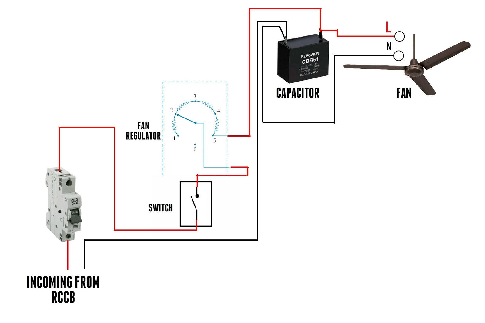
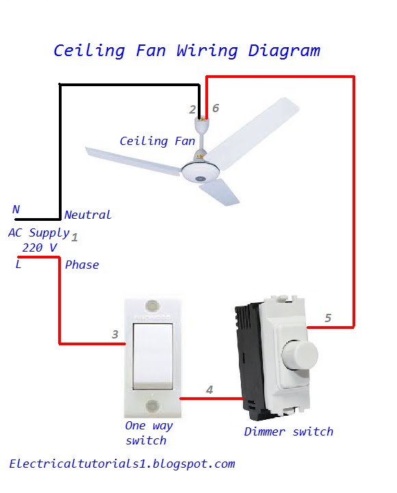
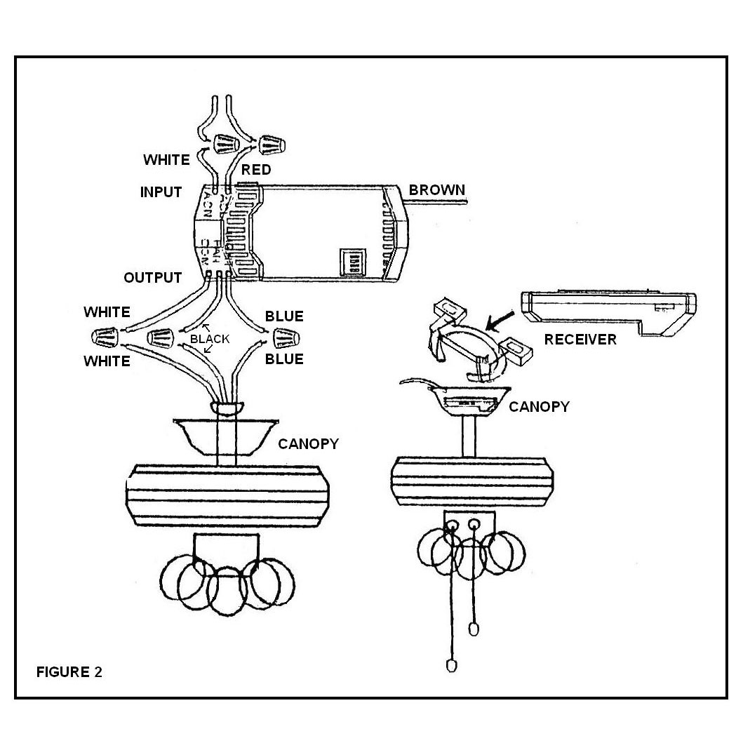
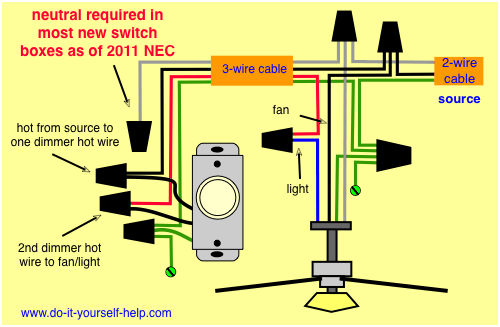
 Title : Electric Ceiling Fan Wiring Diagram
Category : Wiring Diagram
Format : PDF
Title : Electric Ceiling Fan Wiring Diagram
Category : Wiring Diagram
Format : PDF