e60-m5-fuse-map-5series-net-wiring-diagram.pdf
1 / 97
100%
Download Full Diagram Via this App!!!!
Get Diagram Now! DOWNLOAD NOW
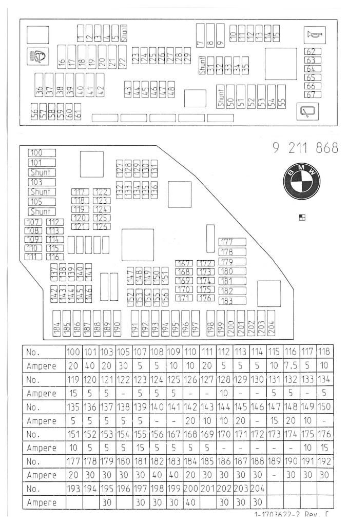
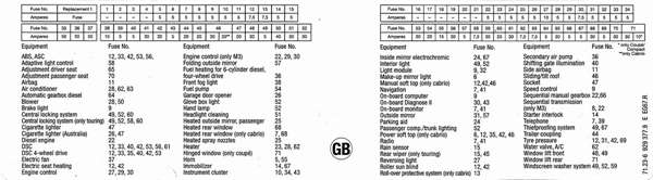
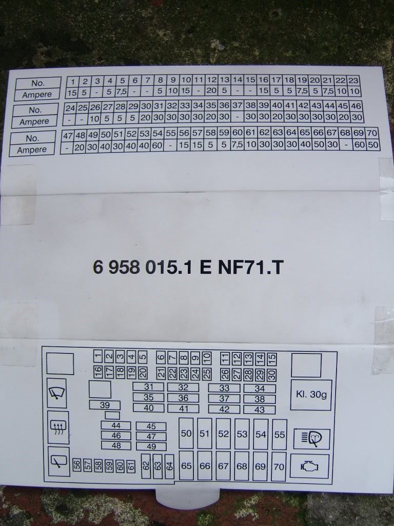
 Title : E60 M5 Fuse Map 5series Net Wiring Diagram
Category : Wiring Diagram
Format : PDF
Title : E60 M5 Fuse Map 5series Net Wiring Diagram
Category : Wiring Diagram
Format : PDF