diagrams-for-lincoln-town-car.pdf
1 / 99
100%
Download Full Diagram Via this App!!!!
Get Diagram Now! DOWNLOAD NOW
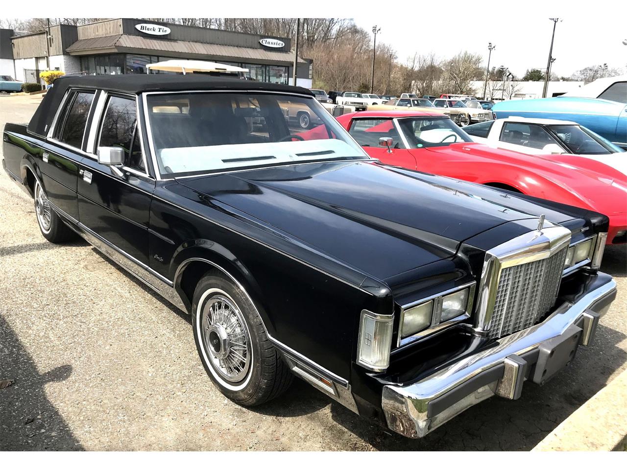
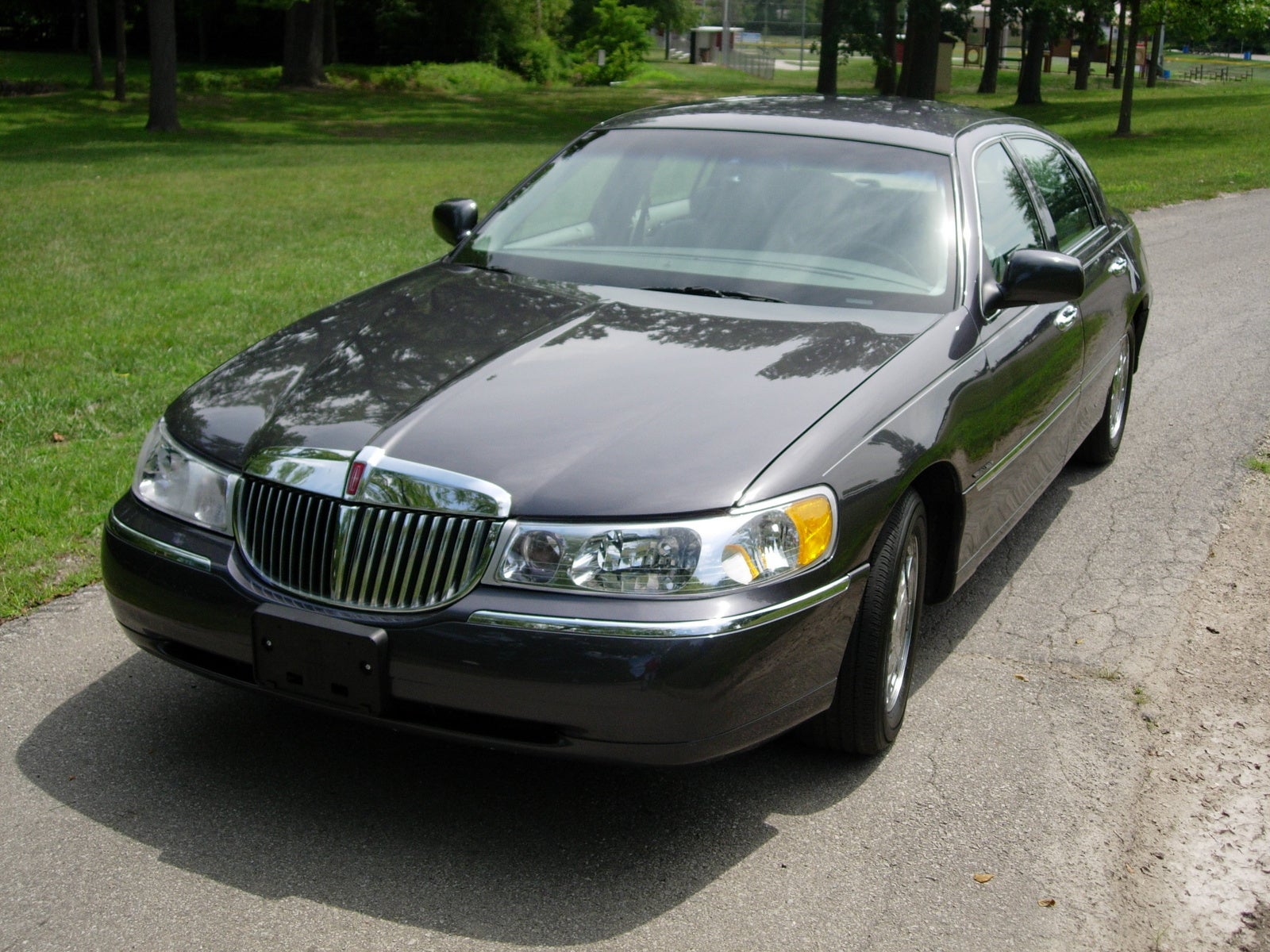
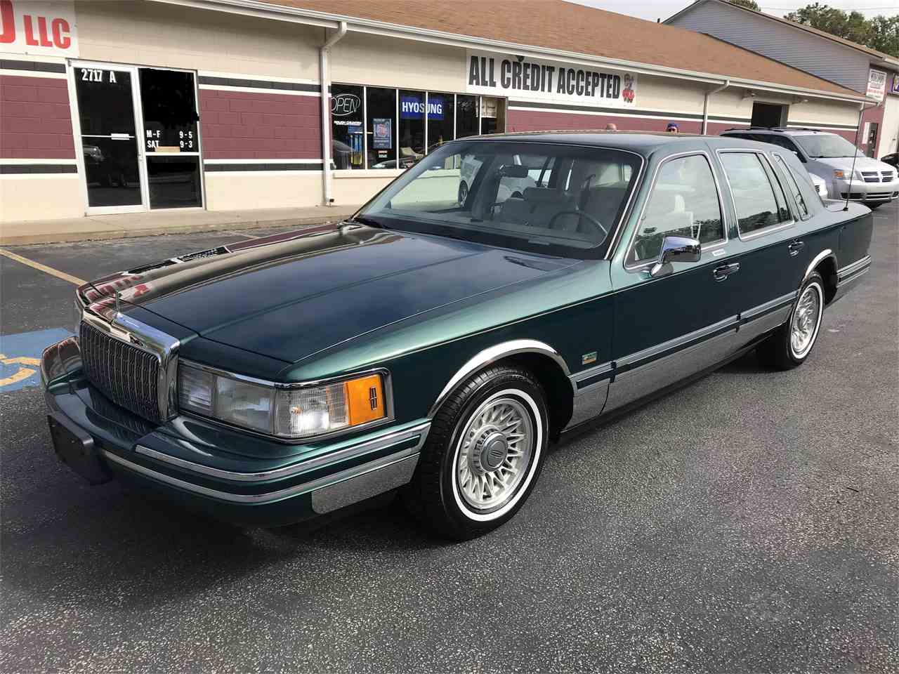
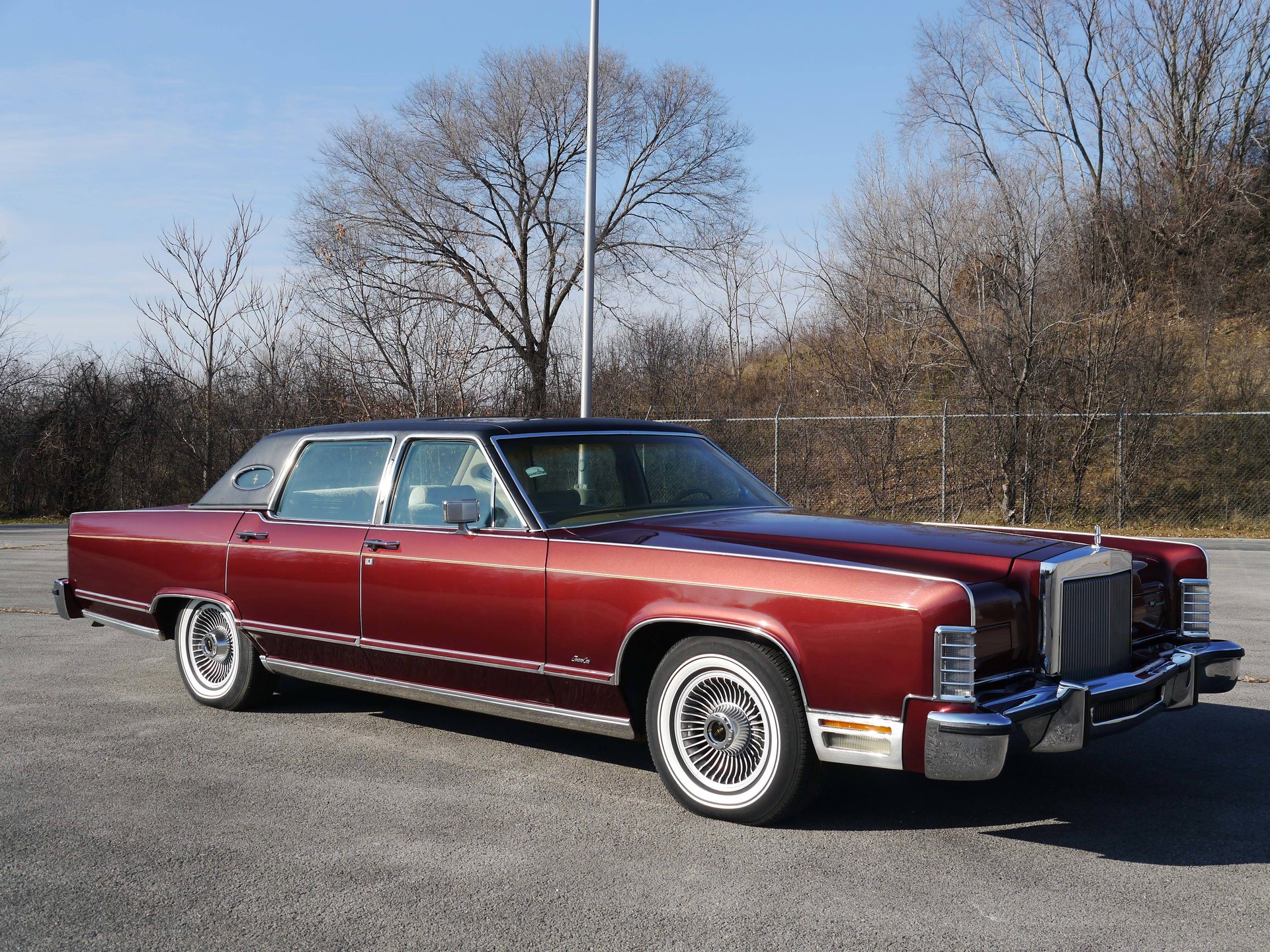
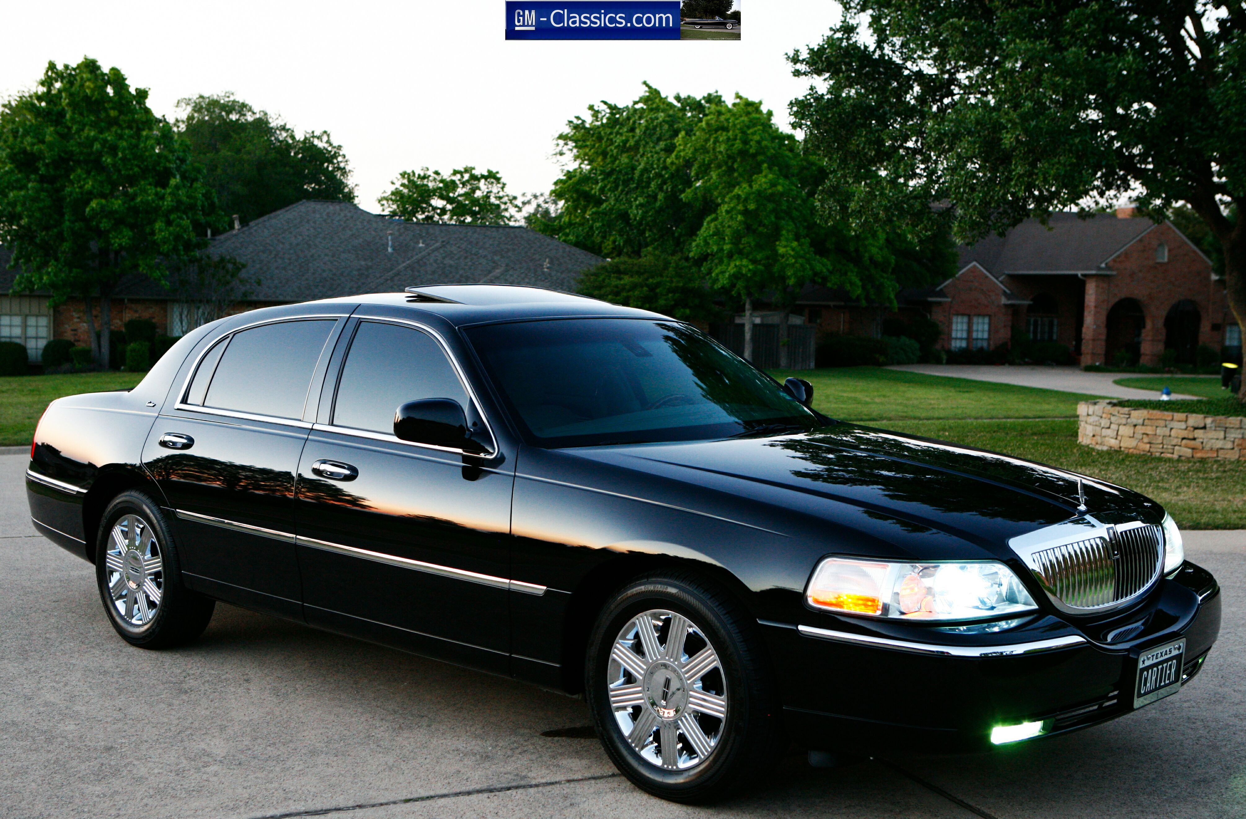
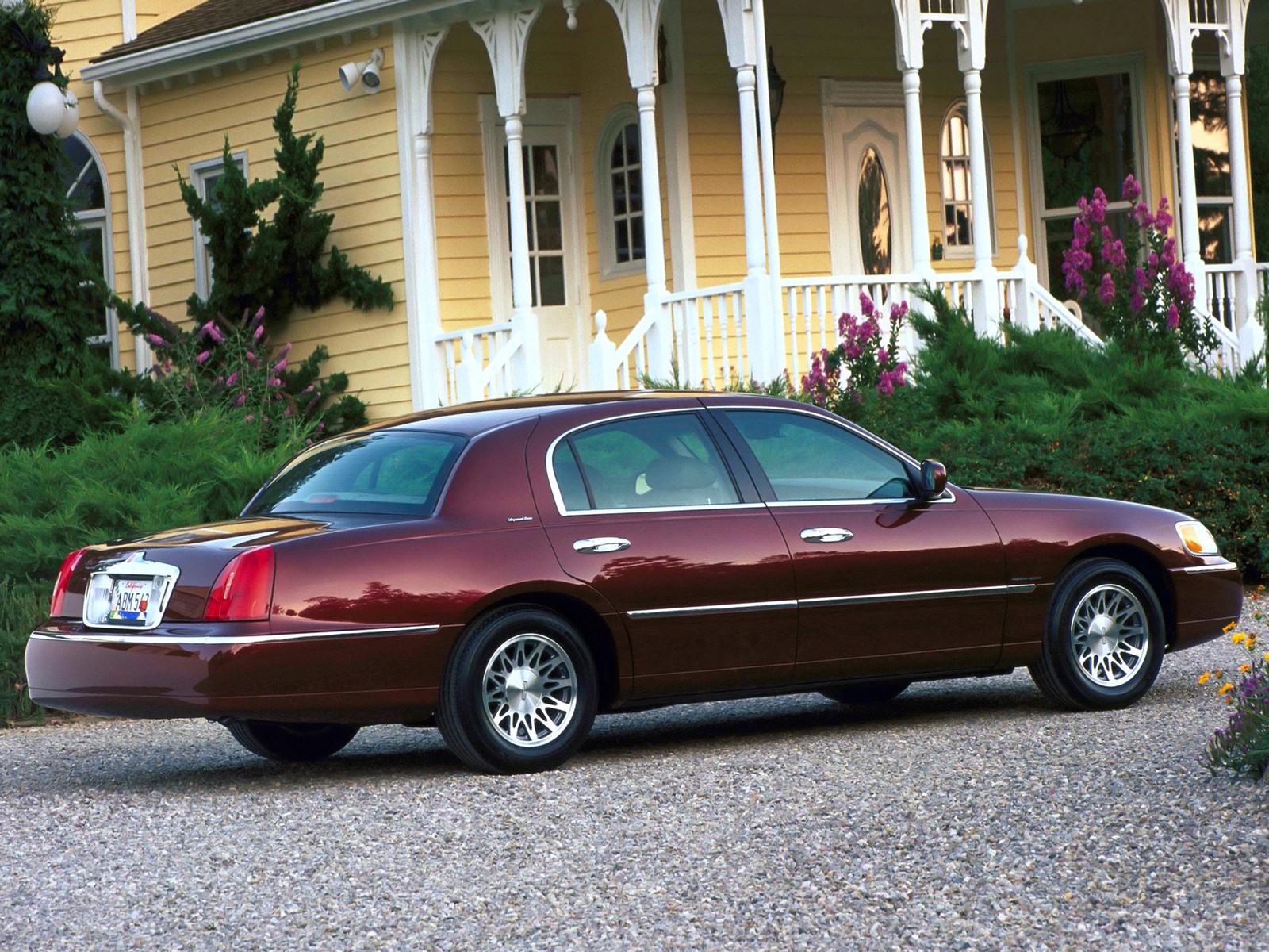
 Title : Diagrams For Lincoln Town Car
Category : Town Car
Format : PDF
Title : Diagrams For Lincoln Town Car
Category : Town Car
Format : PDF