daikin-air-conditioning-wiring-diagram.pdf
1 / 97
100%
Download Full Diagram Via this App!!!!
Get Diagram Now! DOWNLOAD NOW
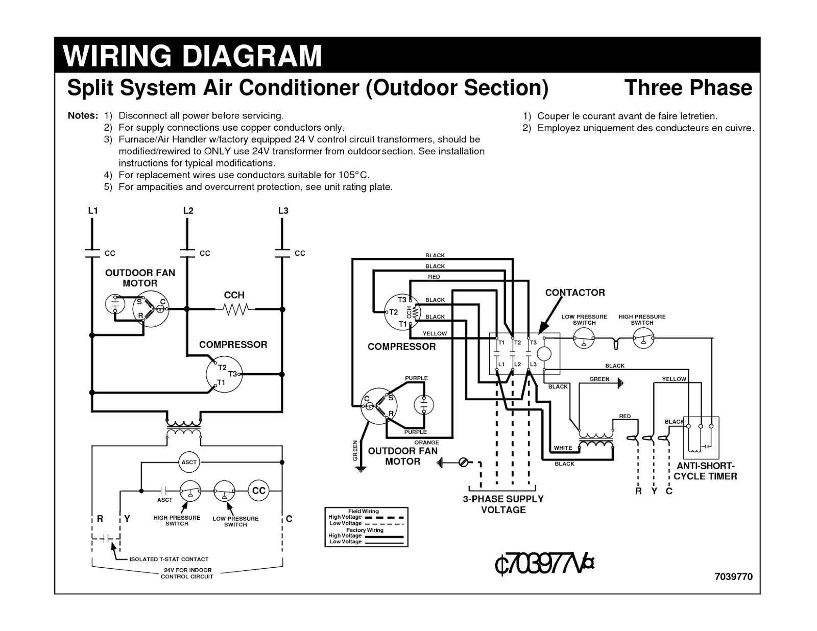
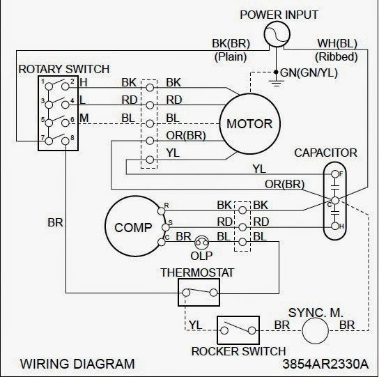
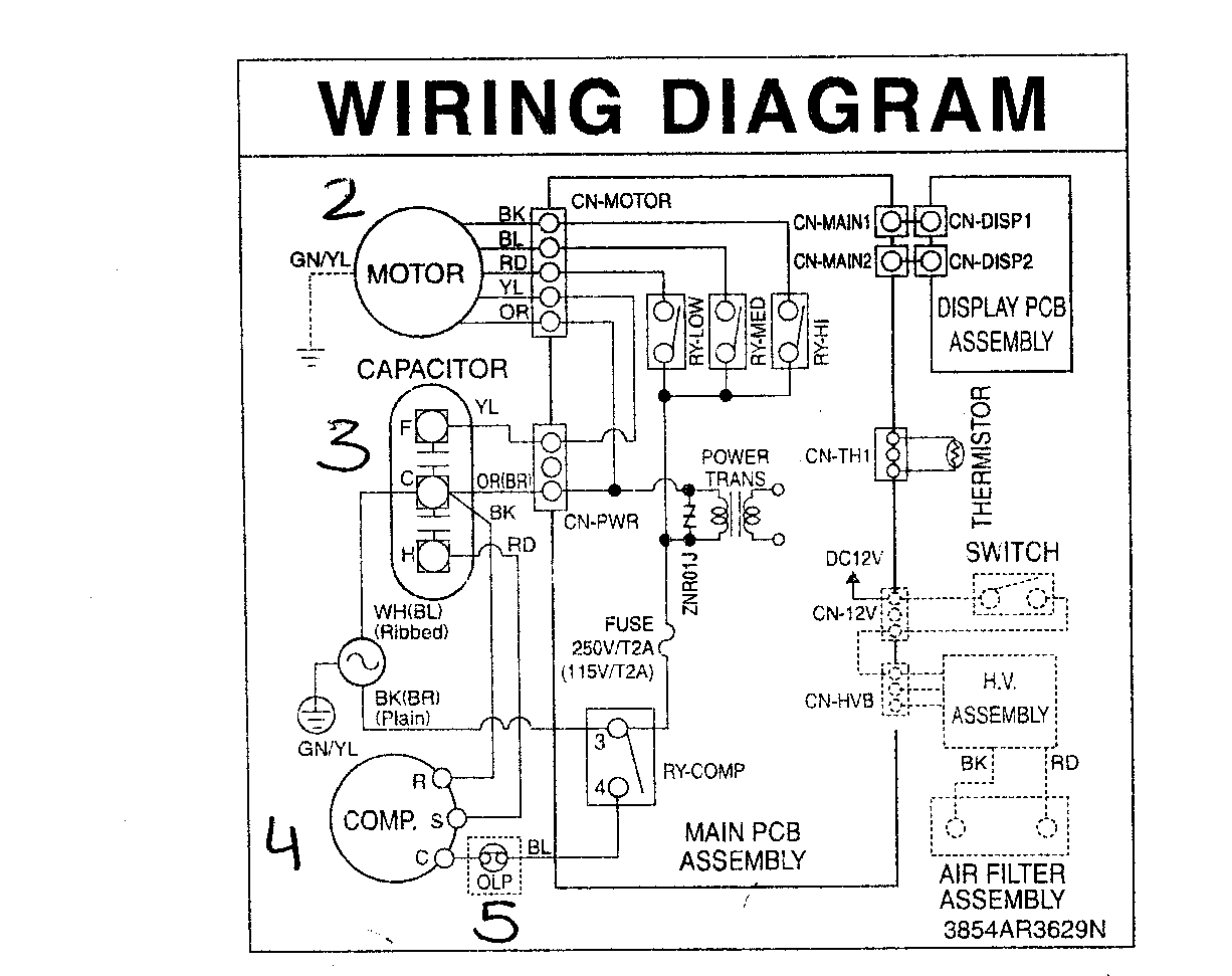
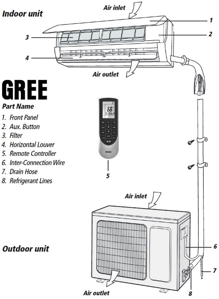
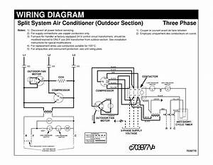 Title : Daikin Air Conditioning Wiring Diagram
Category : Wiring Diagram
Format : PDF
Title : Daikin Air Conditioning Wiring Diagram
Category : Wiring Diagram
Format : PDF