c-band-lnb-skew-diagram-wiring-diagram.pdf
1 / 100
100%
Download Full Diagram Via this App!!!!
Get Diagram Now! DOWNLOAD NOW
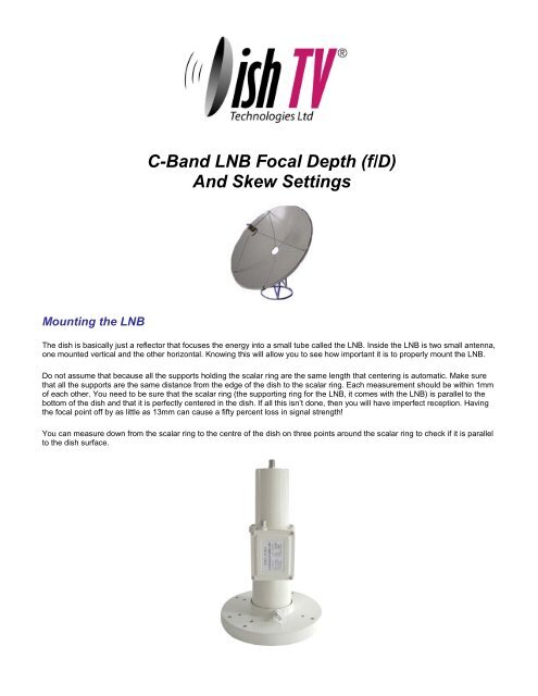
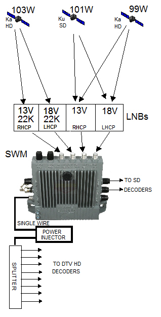
 Title : C Band Lnb Skew Diagram Wiring Diagram
Category : Wiring Diagram
Format : PDF
Title : C Band Lnb Skew Diagram Wiring Diagram
Category : Wiring Diagram
Format : PDF