block-diagram-basics.pdf
100%

Block Diagram Basics


HTTP://MYDIAGRAM.ONLINE
Revision 3.8 (05/2022)
© 2022 HTTP://MYDIAGRAM.ONLINE. All Rights Reserved.

TABLE OF CONTENTS

Cover1
Table of Contents2
AIR CONDITIONING3
ANTI-LOCK BRAKES4
ANTI-THEFT5
BODY CONTROL MODULES6
COMPUTER DATA LINES7
COOLING FAN8
CRUISE CONTROL9
DEFOGGERS10
ELECTRONIC SUSPENSION11
ENGINE PERFORMANCE12
EXTERIOR LIGHTS13
GROUND DISTRIBUTION14
HEADLIGHTS15
HORN16
INSTRUMENT CLUSTER17
INTERIOR LIGHTS18
POWER DISTRIBUTION19
POWER DOOR LOCKS20
POWER MIRRORS21
POWER SEATS22
POWER WINDOWS23
RADIO24
SHIFT INTERLOCK25
STARTING/CHARGING26
SUPPLEMENTAL RESTRAINTS27
TRANSMISSION28
TRUNK, TAILGATE, FUEL DOOR29
WARNING SYSTEMS30
WIPER/WASHER31
Diagnostic Flowchart #332
Diagnostic Flowchart #433
Case Study #1 - Real-World Failure34
Case Study #2 - Real-World Failure35
Case Study #3 - Real-World Failure36
Case Study #4 - Real-World Failure37
Case Study #5 - Real-World Failure38
Case Study #6 - Real-World Failure39
Hands-On Lab #1 - Measurement Practice40
Hands-On Lab #2 - Measurement Practice41
Hands-On Lab #3 - Measurement Practice42
Hands-On Lab #4 - Measurement Practice43
Hands-On Lab #5 - Measurement Practice44
Hands-On Lab #6 - Measurement Practice45
Checklist & Form #1 - Quality Verification46
Checklist & Form #2 - Quality Verification47
Checklist & Form #3 - Quality Verification48
Checklist & Form #4 - Quality Verification49
AIR CONDITIONING Page 3

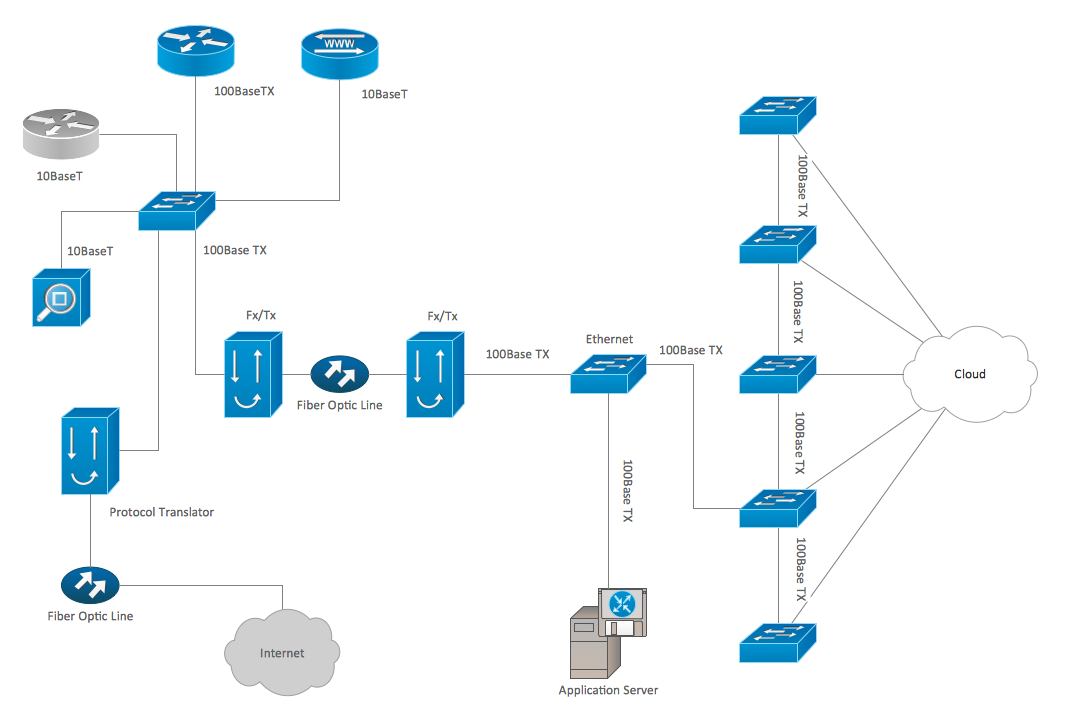
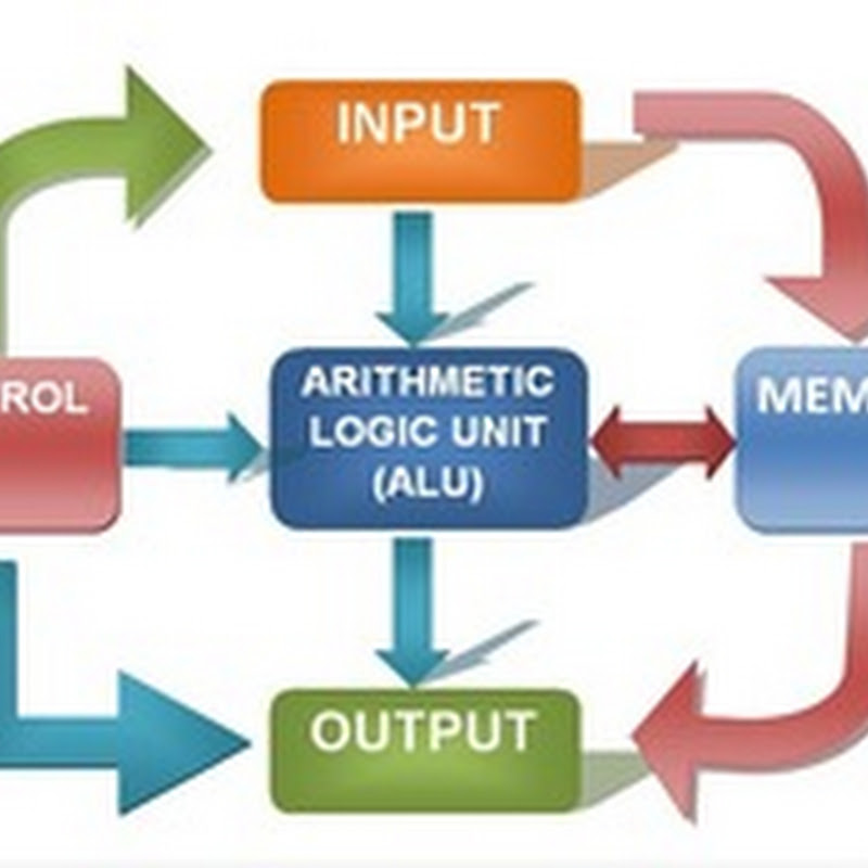
Todays complex electrical architectures have grown far beyond basic mechanical controls. They now include microcontrollers, sensors, and communication buses, all linked via layered wiring systems. Diagnosing faults in such systems requires more than intuition or experienceit demands a logical process supported by accurate tools. Without a systematic approach, troubleshooting quickly turns into guesswork that drains efficiency and reliability.

Diagnostics is the art and science of comparison. It observes how a system should behave versus how it actually behaves. Success begins by establishing reference points: voltage, waveform, or logic state. Each data point captured offers clues that, when combined, reveal the precise fault origin.

### **1. Fundamental Tools**

The foundation of every diagnostic process is the universal measuring instrument. It measures voltage, current, and resistance with accuracy and repeatability. Whether youre checking battery supply, ground integrity, or sensor feedback, the DMM provides the first layer of confirmation. Its beeper and forward-bias tests quickly expose broken links or polarity faults.

The waveform analyzer extends measurement into the time domain. It reveals how voltage varies under load, displaying waveforms that tell stories about circuit activity. For PWM, communication, or switching regulators, oscilloscopes visualize distortion, missing pulses, or delay. Multi-channel scopes can compare input and output to assess signal timing relationships.

non-contact current tools measure current without breaking circuits. They use magnetic induction to detect flow through conductors, ideal for energized installations. Modern DC-capable models reveal startup surges and parasitic draws that static tests may miss.

### **2. Advanced Diagnostic Instruments**

When the problem hides deeper, technicians turn to dedicated diagnostic equipment. Logic analyzers capture serial communication like CAN, LIN, or UART, translating binary signals into human-readable data. This is vital when modules communicate and simple measurements cant explain failures.

Meggers apply high voltage to detect leakage or weak insulation. In critical systems, this prevents catastrophic insulation failure.

Cable analyzers locate breaks, impedance changes, or shorts. Theyre indispensable for high-end communication cables.

At component level, precision analyzers measure electrical parameters with high accuracy. This detects degraded capacitors. infrared imagers visualize temperature anomalies, instantly exposing loose joints, overloaded wires, or hidden shorts.

### **3. Measurement Strategy**

Tools mean little without discipline and logic. Effective troubleshooting follows a structured path:

- **Visual Inspection:** Look for physical damage, wear, or contamination. Over half of faults are found visually.
- **Power & Ground Verification:** Confirm voltage supply and low resistance returns. Voltage drops cause most failures.
- **Signal Analysis:** Observe waveform shapes and timing during real operation.
- **Comparative Testing:** Measure against known-good systems.
- **Functional Simulation:** apply test loads safely to confirm repairs.

Record all observations. Documentation creates traceable knowledge, turning data into predictive maintenance.

### **4. Safety and Calibration**

Safety ensures accuracy. Before testing, inspect probes and leads. Calibrate instruments regularly to avoid misleading data. Always respect CAT ratings: never use a low-rated meter on high-energy systems. For energized HV systems, use differential probes, isolation transformers, or optically isolated links.

### **5. Data Integration and Modern Trends**

Diagnostics is becoming data-driven. IoT-enabled meters and scopes stream data directly to the cloud. This enables remote monitoring, predictive analytics, and fault trending. Automated Test Systems (ATS) now perform hundreds of tests per second, ensuring consistency and reproducibility. Combined with AI-assisted analytics, they recognize fault signatures before failures occur.

### **6. The Human Element**

Despite automation, the human mind remains irreplaceable. Instruments display data, but experience interprets meaning. Skilled engineers correlate symptoms, readings, and history. They know that a strange voltage or waveform may be a side effect of another fault. Effective diagnosis combines reasoning with field sense.

Ultimately, the goal is not just to measure, but to understand. The right tools amplify insight, turning electrical behavior into a readable story. Mastering measurement transforms chaos into claritythe essence of intelligent troubleshooting.

Figure 1
ANTI-LOCK BRAKES Page 4

Electrical hazards often appear without warning, so preparation is vital. Start by reviewing the service documentation so you know where energy can flow. Shut down batteries, inverters, and chargers before doing any work. Keep the emergency shutdown control exposed and within arm’s reach.

Treat every harness with mechanical respect, not just electrical caution. Keep weight off the connector and avoid kinking the cable where it enters the plug. When soldering, use ventilation and heat-resistant gloves. Inspect crimp terminals for uniform pressure and avoid cold joints. Every careful action today prevents a failure tomorrow.

Before reactivation, verify continuity, fuse integrity, and proper grounding. Restore power slowly while observing for abnormal current draw or temperature rise. Log all measured data so future troubleshooting has a baseline. Professional work means you never skip safety just because you’ve “done this a hundred times.”

Figure 2
ANTI-THEFT Page 5

Schematics use drawn symbols to represent hardware and compact abbreviations to stand in for long component descriptions. The little battery symbol may not match the real unit, but it marks a positive feed point. You’ll normally see resistors drawn as zigzags or boxes, diodes as arrows and bars, and relays as coils driving contacts.

Abbreviations carry critical context when you trace a harness. You’ll see REF (reference), TPS (throttle position sensor), RPM (speed signal), 5V REG (regulated 5 V source), and LIN (local interconnect network). Most service docs assign connector IDs like C101 / C205 so you can physically locate that plug in the loom.

Because each manufacturer can redefine a code, never assume two diagrams mean the same thing. A tag like REF might mean voltage reference in one drawing, but “chassis reference” in another, which matters if “Block Diagram Basics” is being diagnosed in Diagram Basics. To protect modules in 2026, read the legend, confirm signal role, and document your test point plus notes to http://mydiagram.online / https://http://mydiagram.online/block-diagram-basics/MYDIAGRAM.ONLINE.

Figure 3
BODY CONTROL MODULES Page 6

The choice of wire color and size is a deliberate engineering process to keep every electrical circuit functioning properly.
Insulation color offers an immediate clue to the wire’s purpose, and its diameter dictates the safe current-carrying limit.
In many control systems, red is constant voltage, yellow represents switched power, and black indicates ground or return.
Ignoring these conventions leads to confusion, especially when multiple technicians share the same wiring harness.
Consistency in color and gauge coding improves safety and keeps maintenance records traceable in “Block Diagram Basics”.

In Diagram Basics, wiring standards are shaped by decades of international collaboration between automotive, industrial, and electronics sectors.
Documents like ISO 6722, SAE J1128, and IEC 60228 define the acceptable materials, cross-sectional areas, and temperature ratings for conductors.
These standards also specify insulation thickness, labeling format, and test procedures for current capacity.
A 2.5 mm² or 14 AWG cable usually supports 25A at room temperature, yet needs derating in hotter climates.
Knowing these limits helps avoid heat damage, voltage drops, and early wear, keeping “Block Diagram Basics” dependable under all conditions.

Service teams should always log each wiring modification with clear details.
If replacing or extending cables, keep color and gauge consistent with the original harness.
When alternate wire sizes are used, confirm their current rating and insulation rating meet the original spec.
Apply markers or labeled sleeves to maintain color uniformity during temporary fixes.
Once finished, record updates in http://mydiagram.online, include the date (2026), and store revised diagrams at https://http://mydiagram.online/block-diagram-basics/MYDIAGRAM.ONLINE.
Recording and storing data builds a transparent service log that protects both technicians and the organization.

Figure 4
COMPUTER DATA LINES Page 7

Power distribution plays a vital role in ensuring electrical stability, safety, and consistent operation.
It determines how energy flows from one power source to several circuits supporting each part of “Block Diagram Basics”.
A well-designed power network avoids overloads, voltage fluctuations, and transmission losses.
Systematic power routing allows smooth operation and reduces risk of short-circuiting or component damage.
Essentially, it turns raw electrical input into a controlled and efficient power delivery framework.

Reliable power delivery depends on correct load calculation and structured circuit design.
Each wire, fuse, and relay must be rated according to its current capacity, environmental exposure, and operational duration.
Across Diagram Basics, professionals follow ISO 16750, IEC 61000, and SAE J1113 to achieve consistent and safe designs.
Power and communication lines must be separated to prevent electromagnetic interference (EMI) and maintain signal integrity.
Fuse holders, relay panels, and grounding points should be easily accessible and clearly labeled for maintenance.
These design standards allow “Block Diagram Basics” to perform efficiently despite environmental and electrical stress.

Testing and validation represent the final stages in confirming power system integrity.
Technicians must measure voltage levels, continuity, and insulation resistance to ensure full compliance with design parameters.
Changes made during installation must be reflected in both schematic drawings and electronic logs.
Inspection photos, voltage readings, and test reports should be stored in http://mydiagram.online for long-term reference.
Adding the project year (2026) and documentation link (https://http://mydiagram.online/block-diagram-basics/MYDIAGRAM.ONLINE) creates a transparent and traceable record for future maintenance.
Adopting careful documentation and safety methods allows “Block Diagram Basics” to remain stable and reliable for years.

Figure 5
COOLING FAN Page 8

It forms the core safeguard that protects human life, systems, and infrastructure from electrical failures.
It provides a controlled route for current to flow harmlessly into the ground, keeping voltage balanced.
Lack of grounding in “Block Diagram Basics” may cause surges, instability, and dangerous energy buildup.
Proper grounding minimizes signal noise, improves reliability, and prolongs hardware durability.
Within Diagram Basics, grounding is integral to the safe and efficient transmission of electrical power.

Creating an efficient grounding layout starts by analyzing electrical loads, soil conditions, and safety parameters.
Grounding electrodes should be installed in areas with low resistivity and adequate moisture for better conductivity.
Across Diagram Basics, engineers rely on IEC 60364 and IEEE 142 to guide compliant grounding design.
Conductors should withstand high current flow while maintaining low resistance and structural integrity.
All grounding locations should link together to maintain uniform voltage across the entire system.
Applying these standards allows “Block Diagram Basics” to maintain safety, durability, and electrical stability.

Routine inspections help preserve grounding effectiveness and prevent system degradation.
Engineers need to verify resistance values, examine for corrosion, and confirm strong bonding connections.
If resistance readings exceed allowable limits, maintenance and immediate correction are required.
Inspection and test reports should be archived to prove compliance and ensure traceability.
Testing each 2026 ensures the system maintains consistent safety and operational reliability.
Accurate records and routine inspections keep “Block Diagram Basics” safe, efficient, and compliant over time.

Figure 6
CRUISE CONTROL Page 9

Block Diagram Basics Full Manual – Connector Index & Pinout Reference 2026

Connectors play a vital role in every electrical or electronic system, acting as the link between multiple circuits, harnesses, and modules. To help technicians identify each one easily, manufacturers assign unique codes such as C305, referred to as *connector indexes*. Such indexing allows fast circuit tracking and prevents confusion when troubleshooting.

A connector index usually includes both the connector number and the circuit group or system category. For instance, connectors beginning with “E” may belong to the engine harness, while “B” could represent the body network. It helps technicians quickly determine where each connector is located physically.

During maintenance or troubleshooting, understanding the connector index helps avoid confusion when reading schematic pages. Knowing the exact connector code minimizes time wasted during repair sessions. In large systems, proper connector indexing ensures all diagrams match real harness layouts.

Figure 7
DEFOGGERS Page 10

Block Diagram Basics Wiring Guide – Sensor Inputs 2026

Monitoring rotational speed is vital for engine control, transmission management, and braking systems. {Common examples include wheel speed sensors, crankshaft position sensors, and transmission output sensors.|These sensors generate frequency-based signals corresponding to shaft or wheel movement.|Each ...

Hall-effect sensors produce voltage pulses when a magnetic target passes near the sensing element. {Optical sensors use light interruption or reflection to measure rotational motion accurately.|Each method converts physical movement into an electronic pulse signal.|The ECU interprets these pulses to calculate real-time spe...

A failing sensor often leads to incorrect speed display or ABS malfunction. {Understanding how speed sensors work ensures correct diagnosis and calibration during replacement.|Proper speed signal analysis enhances vehicle safety and drive control.|Mastery of speed input circuits supports efficient repai...

Figure 8
ELECTRONIC SUSPENSION Page 11

Block Diagram Basics – Sensor Inputs 2026

Pressure sensors measure fluid or air pressure and convert it into an electrical signal for monitoring systems. {They help maintain safety and efficiency by reporting pressure variations to the control unit.|Monitoring pressure ensures balanced operation in engines, brakes, and HVAC circuits.|Accurate pressure data allow...

Most automotive pressure sensors use piezoresistive elements that vary resistance under stress. {The signal is processed by the ECU to adjust system response such as fuel injection, boost control, or safety cutoff.|Electrical output is scaled to reflect actual mechanical pressure values.|The controller interprets voltage ...

A deviation from reference voltage or resistance indicates a faulty pressure sensor. {Proper maintenance of pressure sensors ensures reliable system feedback and longer component lifespan.|Consistent calibration prevents false alerts or control instability.|Understanding pressure sensor inputs helps improve s...

Figure 9
ENGINE PERFORMANCE Page 12

Block Diagram Basics Full Manual – Actuator Outputs Guide 2026

A solenoid converts electrical current into linear motion, making it ideal for valves and mechanical locks. They operate by energizing a coil that generates a magnetic field to move a plunger or core.

Pulse-width modulation (PWM) can also be used to regulate movement intensity or speed. Without proper suppression, the collapsing magnetic field could damage control electronics.

Inspect wiring, connectors, and driver circuits for signs of overheating or corrosion. Knowledge of solenoid control is vital for maintaining accuracy and safety in modern systems.

Figure 10
EXTERIOR LIGHTS Page 13

As the distributed nervous system of the
vehicle, the communication bus eliminates bulky point-to-point wiring by
delivering unified message pathways that significantly reduce harness
mass and electrical noise. By enforcing timing discipline and
arbitration rules, the system ensures each module receives critical
updates without interruption.

Modern platforms rely on a hierarchy of standards including CAN for
deterministic control, LIN for auxiliary functions, FlexRay for
high-stability timing loops, and Ethernet for high-bandwidth sensing.
Each protocol fulfills unique performance roles that enable safe
coordination of braking, torque management, climate control, and
driver-assistance features.

Technicians often
identify root causes such as thermal cycling, micro-fractured
conductors, or grounding imbalances that disrupt stable signaling.
Careful inspection of routing, shielding continuity, and connector
integrity restores communication reliability.

Figure 11
GROUND DISTRIBUTION Page 14

Protection systems in Block Diagram Basics 2026 Diagram Basics rely on fuses and relays
to form a controlled barrier between electrical loads and the vehicle’s
power distribution backbone. These elements react instantly to abnormal
current patterns, stopping excessive amperage before it cascades into
critical modules. By segmenting circuits into isolated branches, the
system protects sensors, control units, lighting, and auxiliary
equipment from thermal stress and wiring burnout.

In modern architectures, relays handle repetitive activation
cycles, executing commands triggered by sensors or control software.
Their isolation capabilities reduce stress on low‑current circuits,
while fuses provide sacrificial protection whenever load spikes exceed
tolerance thresholds. Together they create a multi‑layer defense grid
adaptable to varying thermal and voltage demands.

Common failures within fuse‑relay assemblies often trace back to
vibration fatigue, corroded terminals, oxidized blades, weak coil
windings, or overheating caused by loose socket contacts. Drivers may
observe symptoms such as flickering accessories, intermittent actuator
response, disabled subsystems, or repeated fuse blows. Proper
diagnostics require voltage‑drop measurements, socket stability checks,
thermal inspection, and coil resistance evaluation.

Figure 12
HEADLIGHTS Page 15

Test points play a foundational role in Block Diagram Basics 2026 Diagram Basics by
providing sensor baseline correlation distributed across the electrical
network. These predefined access nodes allow technicians to capture
stable readings without dismantling complex harness assemblies. By
exposing regulated supply rails, clean ground paths, and buffered signal
channels, test points simplify fault isolation and reduce diagnostic
time when tracking voltage drops, miscommunication between modules, or
irregular load behavior.

Using their strategic layout, test points enable ECU
return-path evaluation, ensuring that faults related to thermal drift,
intermittent grounding, connector looseness, or voltage instability are
detected with precision. These checkpoints streamline the
troubleshooting workflow by eliminating unnecessary inspection of
unrelated harness branches and focusing attention on the segments most
likely to generate anomalies.

Frequent discoveries made at reference nodes
involve irregular waveform signatures, contact oxidation, fluctuating
supply levels, and mechanical fatigue around connector bodies.
Diagnostic procedures include load simulation, voltage-drop mapping, and
ground potential verification to ensure that each subsystem receives
stable and predictable electrical behavior under all operating
conditions.

Figure 13
HORN Page 16

In modern
systems, structured diagnostics rely heavily on high-speed sampling
verification, allowing technicians to capture consistent reference data
while minimizing interference from adjacent circuits. This structured
approach improves accuracy when identifying early deviations or subtle
electrical irregularities within distributed subsystems.

Technicians utilize these measurements to evaluate waveform stability,
dynamic waveform distortion analysis, and voltage behavior across
multiple subsystem domains. Comparing measured values against
specifications helps identify root causes such as component drift,
grounding inconsistencies, or load-induced fluctuations.

Common measurement findings include fluctuating supply rails, irregular
ground returns, unstable sensor signals, and waveform distortion caused
by EMI contamination. Technicians use oscilloscopes, multimeters, and
load probes to isolate these anomalies with precision.

Figure 14
INSTRUMENT CLUSTER Page 17

Troubleshooting for Block Diagram Basics 2026 Diagram Basics begins with primary
verification cycle, ensuring the diagnostic process starts with clarity
and consistency. By checking basic system readiness, technicians avoid
deeper misinterpretations.

Field testing
incorporates reaction-time deviation study, providing insight into
conditions that may not appear during bench testing. This highlights
environment‑dependent anomalies.

Branches exposed to road vibration often develop micro‑cracks in
conductors. Flex tests combined with continuity monitoring help identify
weak segments.

Figure 15
INTERIOR LIGHTS Page 18

Common fault patterns in Block Diagram Basics 2026 Diagram Basics frequently stem from
progressive sensor drift under heat load, a condition that introduces
irregular electrical behavior observable across multiple subsystems.
Early-stage symptoms are often subtle, manifesting as small deviations
in baseline readings or intermittent inconsistencies that disappear as
quickly as they appear. Technicians must therefore begin diagnostics
with broad-spectrum inspection, ensuring that fundamental supply and
return conditions are stable before interpreting more complex
indicators.

When examining faults tied to progressive sensor drift under heat load,
technicians often observe fluctuations that correlate with engine heat,
module activation cycles, or environmental humidity. These conditions
can cause reference rails to drift or sensor outputs to lose linearity,
leading to miscommunication between control units. A structured
diagnostic workflow involves comparing real-time readings to known-good
values, replicating environmental conditions, and isolating behavior
changes under controlled load simulations.

Left unresolved, progressive sensor drift under heat load may
cause cascading failures as modules attempt to compensate for distorted
data streams. This can trigger false DTCs, unpredictable load behavior,
delayed actuator response, and even safety-feature interruptions.
Comprehensive analysis requires reviewing subsystem interaction maps,
recreating stress conditions, and validating each reference point’s
consistency under both static and dynamic operating states.

Figure 16
POWER DISTRIBUTION Page 19

For
long-term system stability, effective electrical upkeep prioritizes
vibration-induced wear countermeasures, allowing technicians to maintain
predictable performance across voltage-sensitive components. Regular
inspections of wiring runs, connector housings, and grounding anchors
help reveal early indicators of degradation before they escalate into
system-wide inconsistencies.

Technicians
analyzing vibration-induced wear countermeasures typically monitor
connector alignment, evaluate oxidation levels, and inspect wiring for
subtle deformations caused by prolonged thermal exposure. Protective
dielectric compounds and proper routing practices further contribute to
stable electrical pathways that resist mechanical stress and
environmental impact.

Failure
to maintain vibration-induced wear countermeasures can lead to cascading
electrical inconsistencies, including voltage drops, sensor signal
distortion, and sporadic subsystem instability. Long-term reliability
requires careful documentation, periodic connector service, and
verification of each branch circuit’s mechanical and electrical health
under both static and dynamic conditions.

Figure 17
POWER DOOR LOCKS Page 20

The appendix for Block Diagram Basics 2026 Diagram Basics serves as a consolidated
reference hub focused on connector family classification and labeling
consistency, offering technicians consistent terminology and structured
documentation practices. By collecting technical descriptors,
abbreviations, and classification rules into a single section, the
appendix streamlines interpretation of wiring layouts across diverse
platforms. This ensures that even complex circuit structures remain
approachable through standardized definitions and reference cues.

Material within the appendix covering connector
family classification and labeling consistency often features
quick‑access charts, terminology groupings, and definition blocks that
serve as anchors during diagnostic work. Technicians rely on these
consolidated references to differentiate between similar connector
profiles, categorize branch circuits, and verify signal
classifications.

Comprehensive references for connector family classification and
labeling consistency also support long‑term documentation quality by
ensuring uniform terminology across service manuals, schematics, and
diagnostic tools. When updates occur—whether due to new sensors, revised
standards, or subsystem redesigns—the appendix remains the authoritative
source for maintaining alignment between engineering documentation and
real‑world service practices.

Figure 18
POWER MIRRORS Page 21

Deep analysis of signal integrity in Block Diagram Basics 2026 Diagram Basics requires
investigating how differential-mode noise in sensor feedback circuits
disrupts expected waveform performance across interconnected circuits.
As signals propagate through long harnesses, subtle distortions
accumulate due to impedance shifts, parasitic capacitance, and external
electromagnetic stress. This foundational assessment enables technicians
to understand where integrity loss begins and how it
evolves.

Patterns associated with differential-mode noise in
sensor feedback circuits often appear during subsystem
switching—ignition cycles, relay activation, or sudden load
redistribution. These events inject disturbances through shared
conductors, altering reference stability and producing subtle waveform
irregularities. Multi‑state capture sequences are essential for
distinguishing true EMC faults from benign system noise.

Left uncorrected, differential-mode noise in sensor feedback circuits
can progress into widespread communication degradation, module
desynchronization, or unstable sensor logic. Technicians must verify
shielding continuity, examine grounding symmetry, analyze differential
paths, and validate signal behavior across environmental extremes. Such
comprehensive evaluation ensures repairs address root EMC
vulnerabilities rather than surface‑level symptoms.

Figure 19
POWER SEATS Page 22

Advanced EMC evaluation in Block Diagram Basics 2026 Diagram Basics requires close
study of bias‑line perturbation affecting module logic thresholds, a
phenomenon that can significantly compromise waveform predictability. As
systems scale toward higher bandwidth and greater sensitivity, minor
deviations in signal symmetry or reference alignment become amplified.
Understanding the initial conditions that trigger these distortions
allows technicians to anticipate system vulnerabilities before they
escalate.

Systems experiencing
bias‑line perturbation affecting module logic thresholds frequently show
inconsistencies during fast state transitions such as ignition
sequencing, data bus arbitration, or actuator modulation. These
inconsistencies originate from embedded EMC interactions that vary with
harness geometry, grounding quality, and cable impedance. Multi‑stage
capture techniques help isolate the root interaction layer.

If left unresolved, bias‑line
perturbation affecting module logic thresholds may trigger cascading
disruptions including frame corruption, false sensor readings, and
irregular module coordination. Effective countermeasures include
controlled grounding, noise‑filter deployment, re‑termination of
critical paths, and restructuring of cable routing to minimize
electromagnetic coupling.

Figure 20
POWER WINDOWS Page 23

A comprehensive
assessment of waveform stability requires understanding the effects of
transient ESD events injecting disruptive charge into module inputs, a
factor capable of reshaping digital and analog signal profiles in subtle
yet impactful ways. This initial analysis phase helps technicians
identify whether distortions originate from physical harness geometry,
electromagnetic ingress, or internal module reference instability.

When transient ESD events injecting disruptive charge into module
inputs is active within a vehicle’s electrical environment, technicians
may observe shift in waveform symmetry, rising-edge deformation, or
delays in digital line arbitration. These behaviors require examination
under multiple load states, including ignition operation, actuator
cycling, and high-frequency interference conditions. High-bandwidth
oscilloscopes and calibrated field probes reveal the hidden nature of
such distortions.

If
unchecked, transient ESD events injecting disruptive charge into module
inputs can escalate into broader electrical instability, causing
corruption of data frames, synchronization loss between modules, and
unpredictable actuator behavior. Effective corrective action requires
ground isolation improvements, controlled harness rerouting, adaptive
termination practices, and installation of noise-suppression elements
tailored to the affected frequency range.

Figure 21
RADIO Page 24

Deep technical assessment of signal behavior in Block Diagram Basics 2026
Diagram Basics requires understanding how ground-collapse instability under
combined thermal and EMI stress reshapes waveform integrity across
interconnected circuits. As system frequency demands rise and wiring
architectures grow more complex, even subtle electromagnetic
disturbances can compromise deterministic module coordination. Initial
investigation begins with controlled waveform sampling and baseline
mapping.

When ground-collapse instability under combined thermal and EMI stress
is active, waveform distortion may manifest through amplitude
instability, reference drift, unexpected ringing artifacts, or shifting
propagation delays. These effects often correlate with subsystem
transitions, thermal cycles, actuator bursts, or environmental EMI
fluctuations. High‑bandwidth test equipment reveals the microscopic
deviations hidden within normal signal envelopes.

Long‑term exposure to ground-collapse instability under combined
thermal and EMI stress can create cascading waveform degradation,
arbitration failures, module desynchronization, or persistent sensor
inconsistency. Corrective strategies include impedance tuning, shielding
reinforcement, ground‑path rebalancing, and reconfiguration of sensitive
routing segments. These adjustments restore predictable system behavior
under varied EMI conditions.

Figure 22
SHIFT INTERLOCK Page 25

Advanced waveform diagnostics in Block Diagram Basics 2026 Diagram Basics must account
for PWM-driven magnetic noise violating analog threshold margins, a
complex interaction that reshapes both analog and digital signal
behavior across interconnected subsystems. As modern vehicle
architectures push higher data rates and consolidate multiple electrical
domains, even small EMI vectors can distort timing, amplitude, and
reference stability.

Systems exposed to PWM-driven magnetic noise violating
analog threshold margins often show instability during rapid subsystem
transitions. This instability results from interference coupling into
sensitive wiring paths, causing skew, jitter, or frame corruption.
Multi-domain waveform capture reveals how these disturbances propagate
and interact.

If left unresolved, PWM-driven magnetic noise violating analog
threshold margins may evolve into severe operational instability—ranging
from data corruption to sporadic ECU desynchronization. Effective
countermeasures include refining harness geometry, isolating radiated
hotspots, enhancing return-path uniformity, and implementing
frequency-specific suppression techniques.

Figure 23
STARTING/CHARGING Page 26

This section on STARTING/CHARGING explains how these principles apply to diagram basics systems. Focus on repeatable tests, clear documentation, and safe handling. Keep a simple log: symptom → test → reading → decision → fix.

Figure 24
SUPPLEMENTAL RESTRAINTS Page 27

The engineering process behind Harness
Layout Variant #2 evaluates how assembly-oriented connector ordering for
manufacturing interacts with subsystem density, mounting geometry, EMI
exposure, and serviceability. This foundational planning ensures clean
routing paths and consistent system behavior over the vehicle’s full
operating life.

During refinement, assembly-oriented connector ordering for
manufacturing impacts EMI susceptibility, heat distribution, vibration
loading, and ground continuity. Designers analyze spacing, elevation
changes, shielding alignment, tie-point positioning, and path curvature
to ensure the harness resists mechanical fatigue while maintaining
electrical integrity.

Managing assembly-oriented connector ordering for manufacturing
effectively results in improved robustness, simplified maintenance, and
enhanced overall system stability. Engineers apply isolation rules,
structural reinforcement, and optimized routing logic to produce a
layout capable of sustaining long-term operational loads.

Figure 25
TRANSMISSION Page 28

Harness Layout Variant #3 for Block Diagram Basics 2026 Diagram Basics focuses on
temperature-staged cable grouping for mixed thermal zones, an essential
structural and functional element that affects reliability across
multiple vehicle zones. Modern platforms require routing that
accommodates mechanical constraints while sustaining consistent
electrical behavior and long-term durability.

During refinement, temperature-staged cable grouping for mixed thermal
zones can impact vibration resistance, shielding effectiveness, ground
continuity, and stress distribution along key segments. Designers
analyze bundle thickness, elevation shifts, structural transitions, and
separation from high‑interference components to optimize both mechanical
and electrical performance.

If not addressed,
temperature-staged cable grouping for mixed thermal zones may lead to
premature insulation wear, abrasion hotspots, intermittent electrical
noise, or connector fatigue. Balanced tensioning, routing symmetry, and
strategic material selection significantly mitigate these risks across
all major vehicle subsystems.

Figure 26
TRUNK, TAILGATE, FUEL DOOR Page 29

Harness Layout Variant #4 for Block Diagram Basics 2026 Diagram Basics emphasizes battery-bay moisture barriers and
condensate drains, combining mechanical and electrical considerations to maintain cable stability across
multiple vehicle zones. Early planning defines routing elevation, clearance from heat sources, and anchoring
points so each branch can absorb vibration and thermal expansion without overstressing connectors.

In
real-world operation, battery-bay moisture barriers and condensate drains affects signal quality near
actuators, motors, and infotainment modules. Cable elevation, branch sequencing, and anti-chafe barriers
reduce premature wear. A combination of elastic tie-points, protective sleeves, and low-profile clips keeps
bundles orderly yet flexible under dynamic loads.

If overlooked, battery-bay moisture barriers and condensate drains may lead to insulation wear,
loose connections, or intermittent signal faults caused by chafing. Solutions include anchor repositioning,
spacing corrections, added shielding, and branch restructuring to shorten paths and improve long-term
serviceability.

Figure 27
WARNING SYSTEMS Page 30

Diagnostic Flowchart #1 for Block Diagram Basics 2026 Diagram Basics begins with frequency‑domain confirmation of suspected
EMI disturbances, establishing a precise entry point that helps technicians determine whether symptoms
originate from signal distortion, grounding faults, or early‑stage communication instability. A consistent
diagnostic baseline prevents unnecessary part replacement and improves accuracy. As diagnostics progress, frequency‑domain confirmation of suspected EMI disturbances becomes a
critical branch factor influencing decisions relating to grounding integrity, power sequencing, and network
communication paths. This structured logic ensures accuracy even when symptoms appear scattered. If frequency‑domain confirmation of suspected EMI disturbances is
not thoroughly validated, subtle faults can cascade into widespread subsystem instability. Reinforcing each
decision node with targeted measurements improves long‑term reliability and prevents misdiagnosis.

Figure 28
WIPER/WASHER Page 31

Diagnostic Flowchart #2 for Block Diagram Basics 2026 Diagram Basics begins by addressing interactive load‑step testing for
marginal connectors, establishing a clear entry point for isolating electrical irregularities that may appear
intermittent or load‑dependent. Technicians rely on this structured starting node to avoid misinterpretation
of symptoms caused by secondary effects. Throughout the flowchart,
interactive load‑step testing for marginal connectors interacts with verification procedures involving
reference stability, module synchronization, and relay or fuse behavior. Each decision point eliminates entire
categories of possible failures, allowing the technician to converge toward root cause faster. Completing
the flow ensures that interactive load‑step testing for marginal connectors is validated under multiple
operating conditions, reducing the likelihood of recurring issues. The resulting diagnostic trail provides
traceable documentation that improves future troubleshooting accuracy.

Figure 29
Diagnostic Flowchart #3 Page 32

Diagnostic Flowchart #3 for Block Diagram Basics 2026 Diagram Basics initiates with sensor drift verification under
fluctuating reference voltages, establishing a strategic entry point for technicians to separate primary
electrical faults from secondary symptoms. By evaluating the system from a structured baseline, the diagnostic
process becomes far more efficient.
Throughout the analysis, sensor drift verification under fluctuating reference voltages interacts
with branching decision logic tied to grounding stability, module synchronization, and sensor referencing.
Each step narrows the diagnostic window, improving root‑cause accuracy. If sensor drift verification under fluctuating reference voltages is
not thoroughly verified, hidden electrical inconsistencies may trigger cascading subsystem faults. A
reinforced decision‑tree process ensures all potential contributors are validated.

Figure 30
Diagnostic Flowchart #4 Page 33

Diagnostic Flowchart #4 for
Block Diagram Basics 2026 Diagram Basics focuses on thermal‑linked fluctuation detection in ECU decision loops, laying the
foundation for a structured fault‑isolation path that eliminates guesswork and reduces unnecessary component
swapping. The first stage examines core references, voltage stability, and baseline communication health to
determine whether the issue originates in the primary network layer or in a secondary subsystem. Technicians
follow a branched decision flow that evaluates signal symmetry, grounding patterns, and frame stability before
advancing into deeper diagnostic layers. As the evaluation continues, thermal‑linked fluctuation detection in ECU
decision loops becomes the controlling factor for mid‑level branch decisions. This includes correlating
waveform alignment, identifying momentary desync signatures, and interpreting module wake‑timing conflicts. By
dividing the diagnostic pathway into focused electrical domains—power delivery, grounding integrity,
communication architecture, and actuator response—the flowchart ensures that each stage removes entire
categories of faults with minimal overlap. This structured segmentation accelerates troubleshooting and
increases diagnostic precision. The final stage ensures that thermal‑linked fluctuation detection in ECU
decision loops is validated under multiple operating conditions, including thermal stress, load spikes,
vibration, and state transitions. These controlled stress points help reveal hidden instabilities that may not
appear during static testing. Completing all verification nodes ensures long‑term stability, reducing the
likelihood of recurring issues and enabling technicians to document clear, repeatable steps for future
diagnostics.

Figure 31
Case Study #1 - Real-World Failure Page 34

Case Study #1 for Block Diagram Basics 2026 Diagram Basics examines a real‑world failure involving gateway communication
collapse from over‑current heating. The issue first appeared as an intermittent symptom that did not trigger a
consistent fault code, causing technicians to suspect unrelated components. Early observations highlighted
irregular electrical behavior, such as momentary signal distortion, delayed module responses, or fluctuating
reference values. These symptoms tended to surface under specific thermal, vibration, or load conditions,
making replication difficult during static diagnostic tests. Further investigation into gateway communication
collapse from over‑current heating required systematic measurement across power distribution paths, grounding
nodes, and communication channels. Technicians used targeted diagnostic flowcharts to isolate variables such
as voltage drop, EMI exposure, timing skew, and subsystem desynchronization. By reproducing the fault under
controlled conditions—applying heat, inducing vibration, or simulating high load—they identified the precise
moment the failure manifested. This structured process eliminated multiple potential contributors, narrowing
the fault domain to a specific harness segment, component group, or module logic pathway. The confirmed cause
tied to gateway communication collapse from over‑current heating allowed technicians to implement the correct
repair, whether through component replacement, harness restoration, recalibration, or module reprogramming.
After corrective action, the system was subjected to repeated verification cycles to ensure long‑term
stability under all operating conditions. Documenting the failure pattern and diagnostic sequence provided
valuable reference material for similar future cases, reducing diagnostic time and preventing unnecessary part
replacement.

Figure 32
Case Study #2 - Real-World Failure Page 35

Case Study #2 for Block Diagram Basics 2026 Diagram Basics examines a real‑world failure involving sensor contamination
leading to non‑linear analog output distortion. The issue presented itself with intermittent symptoms that
varied depending on temperature, load, or vehicle motion. Technicians initially observed irregular system
responses, inconsistent sensor readings, or sporadic communication drops. Because the symptoms did not follow
a predictable pattern, early attempts at replication were unsuccessful, leading to misleading assumptions
about unrelated subsystems. A detailed investigation into sensor contamination leading to non‑linear analog
output distortion required structured diagnostic branching that isolated power delivery, ground stability,
communication timing, and sensor integrity. Using controlled diagnostic tools, technicians applied thermal
load, vibration, and staged electrical demand to recreate the failure in a measurable environment. Progressive
elimination of subsystem groups—ECUs, harness segments, reference points, and actuator pathways—helped reveal
how the failure manifested only under specific operating thresholds. This systematic breakdown prevented
misdiagnosis and reduced unnecessary component swaps. Once the cause linked to sensor contamination leading
to non‑linear analog output distortion was confirmed, the corrective action involved either reconditioning the
harness, replacing the affected component, reprogramming module firmware, or adjusting calibration parameters.
Post‑repair validation cycles were performed under varied conditions to ensure long‑term reliability and
prevent future recurrence. Documentation of the failure characteristics, diagnostic sequence, and final
resolution now serves as a reference for addressing similar complex faults more efficiently.

Figure 33
Case Study #3 - Real-World Failure Page 36

Case Study #3 for Block Diagram Basics 2026 Diagram Basics focuses on a real‑world failure involving cooling‑fan module
shutdown triggered by internal logic desaturation. Technicians first observed erratic system behavior,
including fluctuating sensor values, delayed control responses, and sporadic communication warnings. These
symptoms appeared inconsistently, often only under specific temperature, load, or vibration conditions. Early
troubleshooting attempts failed to replicate the issue reliably, creating the impression of multiple unrelated
subsystem faults rather than a single root cause. To investigate cooling‑fan module shutdown triggered by
internal logic desaturation, a structured diagnostic approach was essential. Technicians conducted staged
power and ground validation, followed by controlled stress testing that included thermal loading, vibration
simulation, and alternating electrical demand. This method helped reveal the precise operational threshold at
which the failure manifested. By isolating system domains—communication networks, power rails, grounding
nodes, and actuator pathways—the diagnostic team progressively eliminated misleading symptoms and narrowed the
problem to a specific failure mechanism. After identifying the underlying cause tied to cooling‑fan module
shutdown triggered by internal logic desaturation, technicians carried out targeted corrective actions such as
replacing compromised components, restoring harness integrity, updating ECU firmware, or recalibrating
affected subsystems. Post‑repair validation cycles confirmed stable performance across all operating
conditions. The documented diagnostic path and resolution now serve as a repeatable reference for addressing
similar failures with greater speed and accuracy.

Figure 34
Case Study #4 - Real-World Failure Page 37

Case Study #4 for Block Diagram Basics 2026 Diagram Basics examines a high‑complexity real‑world failure involving
transmission torque‑signal misalignment under ripple‑rich supply. The issue manifested across multiple
subsystems simultaneously, creating an array of misleading symptoms ranging from inconsistent module responses
to distorted sensor feedback and intermittent communication warnings. Initial diagnostics were inconclusive
due to the fault’s dependency on vibration, thermal shifts, or rapid load changes. These fluctuating
conditions allowed the failure to remain dormant during static testing, pushing technicians to explore deeper
system interactions that extended beyond conventional troubleshooting frameworks. To investigate transmission
torque‑signal misalignment under ripple‑rich supply, technicians implemented a layered diagnostic workflow
combining power‑rail monitoring, ground‑path validation, EMI tracing, and logic‑layer analysis. Stress tests
were applied in controlled sequences to recreate the precise environment in which the instability
surfaced—often requiring synchronized heat, vibration, and electrical load modulation. By isolating
communication domains, verifying timing thresholds, and comparing analog sensor behavior under dynamic
conditions, the diagnostic team uncovered subtle inconsistencies that pointed toward deeper system‑level
interactions rather than isolated component faults. After confirming the root mechanism tied to transmission
torque‑signal misalignment under ripple‑rich supply, corrective action involved component replacement, harness
reconditioning, ground‑plane reinforcement, or ECU firmware restructuring depending on the failure’s nature.
Technicians performed post‑repair endurance tests that included repeated thermal cycling, vibration exposure,
and electrical stress to guarantee long‑term system stability. Thorough documentation of the analysis method,
failure pattern, and final resolution now serves as a highly valuable reference for identifying and mitigating
similar high‑complexity failures in the future.

Figure 35
Case Study #5 - Real-World Failure Page 38

Case Study #5 for Block Diagram Basics 2026 Diagram Basics investigates a complex real‑world failure involving PWM carrier
interference creating actuator response instability. The issue initially presented as an inconsistent mixture
of delayed system reactions, irregular sensor values, and sporadic communication disruptions. These events
tended to appear under dynamic operational conditions—such as elevated temperatures, sudden load transitions,
or mechanical vibration—which made early replication attempts unreliable. Technicians encountered symptoms
occurring across multiple modules simultaneously, suggesting a deeper systemic interaction rather than a
single isolated component failure. During the investigation of PWM carrier interference creating actuator
response instability, a multi‑layered diagnostic workflow was deployed. Technicians performed sequential
power‑rail mapping, ground‑plane verification, and high‑frequency noise tracing to detect hidden
instabilities. Controlled stress testing—including targeted heat application, induced vibration, and variable
load modulation—was carried out to reproduce the failure consistently. The team methodically isolated
subsystem domains such as communication networks, analog sensor paths, actuator control logic, and module
synchronization timing. This progressive elimination approach identified critical operational thresholds where
the failure reliably emerged. After determining the underlying mechanism tied to PWM carrier interference
creating actuator response instability, technicians carried out corrective actions that ranged from harness
reconditioning and connector reinforcement to firmware restructuring and recalibration of affected modules.
Post‑repair validation involved repeated cycles of vibration, thermal stress, and voltage fluctuation to
ensure long‑term stability and eliminate the possibility of recurrence. The documented resolution pathway now
serves as an advanced reference model for diagnosing similarly complex failures across modern vehicle
platforms.

Figure 36
Case Study #6 - Real-World Failure Page 39

Case Study #6 for Block Diagram Basics 2026 Diagram Basics examines a complex real‑world failure involving ECU logic deadlock
initiated by ripple‑induced reference collapse. Symptoms emerged irregularly, with clustered faults appearing
across unrelated modules, giving the impression of multiple simultaneous subsystem failures. These
irregularities depended strongly on vibration, temperature shifts, or abrupt electrical load changes, making
the issue difficult to reproduce during initial diagnostic attempts. Technicians noted inconsistent sensor
feedback, communication delays, and momentary power‑rail fluctuations that persisted without generating
definitive fault codes. The investigation into ECU logic deadlock initiated by ripple‑induced reference
collapse required a multi‑layer diagnostic strategy combining signal‑path tracing, ground stability
assessment, and high‑frequency noise evaluation. Technicians executed controlled stress tests—including
thermal cycling, vibration induction, and staged electrical loading—to reveal the exact thresholds at which
the fault manifested. Using structured elimination across harness segments, module clusters, and reference
nodes, they isolated subtle timing deviations, analog distortions, or communication desynchronization that
pointed toward a deeper systemic failure mechanism rather than isolated component malfunction. Once ECU logic
deadlock initiated by ripple‑induced reference collapse was identified as the root failure mechanism, targeted
corrective measures were implemented. These included harness reinforcement, connector replacement, firmware
restructuring, recalibration of key modules, or ground‑path reconfiguration depending on the nature of the
instability. Post‑repair endurance runs with repeated vibration, heat cycles, and voltage stress ensured
long‑term reliability. Documentation of the diagnostic sequence and recovery pathway now provides a vital
reference for detecting and resolving similarly complex failures more efficiently in future service
operations.

Figure 37
Hands-On Lab #1 - Measurement Practice Page 40

Hands‑On Lab #1 for Block Diagram Basics 2026 Diagram Basics focuses on high‑frequency ripple detection on power‑rail outputs.
This exercise teaches technicians how to perform structured diagnostic measurements using multimeters,
oscilloscopes, current probes, and differential tools. The initial phase emphasizes establishing a stable
baseline by checking reference voltages, verifying continuity, and confirming ground integrity. These
foundational steps ensure that subsequent measurements reflect true system behavior rather than secondary
anomalies introduced by poor probing technique or unstable electrical conditions. During the measurement
routine for high‑frequency ripple detection on power‑rail outputs, technicians analyze dynamic behavior by
applying controlled load, capturing waveform transitions, and monitoring subsystem responses. This includes
observing timing shifts, duty‑cycle changes, ripple patterns, or communication irregularities. By replicating
real operating conditions—thermal changes, vibration, or electrical demand spikes—technicians gain insight
into how the system behaves under stress. This approach allows deeper interpretation of patterns that static
readings cannot reveal. After completing the procedure for high‑frequency ripple detection on power‑rail
outputs, results are documented with precise measurement values, waveform captures, and interpretation notes.
Technicians compare the observed data with known good references to determine whether performance falls within
acceptable thresholds. The collected information not only confirms system health but also builds long‑term
diagnostic proficiency by helping technicians recognize early indicators of failure and understand how small
variations can evolve into larger issues.

Figure 38
Hands-On Lab #2 - Measurement Practice Page 41

Hands‑On Lab #2 for Block Diagram Basics 2026 Diagram Basics focuses on ignition coil primary and secondary waveform
evaluation. This practical exercise expands technician measurement skills by emphasizing accurate probing
technique, stable reference validation, and controlled test‑environment setup. Establishing baseline
readings—such as reference ground, regulated voltage output, and static waveform characteristics—is essential
before any dynamic testing occurs. These foundational checks prevent misinterpretation caused by poor tool
placement, floating grounds, or unstable measurement conditions. During the procedure for ignition coil
primary and secondary waveform evaluation, technicians simulate operating conditions using thermal stress,
vibration input, and staged subsystem loading. Dynamic measurements reveal timing inconsistencies, amplitude
drift, duty‑cycle changes, communication irregularities, or nonlinear sensor behavior. Oscilloscopes, current
probes, and differential meters are used to capture high‑resolution waveform data, enabling technicians to
identify subtle deviations that static multimeter readings cannot detect. Emphasis is placed on interpreting
waveform shape, slope, ripple components, and synchronization accuracy across interacting modules. After
completing the measurement routine for ignition coil primary and secondary waveform evaluation, technicians
document quantitative findings—including waveform captures, voltage ranges, timing intervals, and noise
signatures. The recorded results are compared to known‑good references to determine subsystem health and
detect early‑stage degradation. This structured approach not only builds diagnostic proficiency but also
enhances a technician’s ability to predict emerging faults before they manifest as critical failures,
strengthening long‑term reliability of the entire system.

Figure 39
Hands-On Lab #3 - Measurement Practice Page 42

Hands‑On Lab #3 for Block Diagram Basics 2026 Diagram Basics focuses on electronic control module wake‑cycle measurement. This
exercise trains technicians to establish accurate baseline measurements before introducing dynamic stress.
Initial steps include validating reference grounds, confirming supply‑rail stability, and ensuring probing
accuracy. These fundamentals prevent distorted readings and help ensure that waveform captures or voltage
measurements reflect true electrical behavior rather than artifacts caused by improper setup or tool noise.
During the diagnostic routine for electronic control module wake‑cycle measurement, technicians apply
controlled environmental adjustments such as thermal cycling, vibration, electrical loading, and communication
traffic modulation. These dynamic inputs help expose timing drift, ripple growth, duty‑cycle deviations,
analog‑signal distortion, or module synchronization errors. Oscilloscopes, clamp meters, and differential
probes are used extensively to capture transitional data that cannot be observed with static measurements
alone. After completing the measurement sequence for electronic control module wake‑cycle measurement,
technicians document waveform characteristics, voltage ranges, current behavior, communication timing
variations, and noise patterns. Comparison with known‑good datasets allows early detection of performance
anomalies and marginal conditions. This structured measurement methodology strengthens diagnostic confidence
and enables technicians to identify subtle degradation before it becomes a critical operational failure.

Figure 40
Hands-On Lab #4 - Measurement Practice Page 43

Hands‑On Lab #4 for Block Diagram Basics 2026 Diagram Basics focuses on module wake‑signal propagation delay evaluation. This
laboratory exercise builds on prior modules by emphasizing deeper measurement accuracy, environment control,
and test‑condition replication. Technicians begin by validating stable reference grounds, confirming regulated
supply integrity, and preparing measurement tools such as oscilloscopes, current probes, and high‑bandwidth
differential probes. Establishing clean baselines ensures that subsequent waveform analysis is meaningful and
not influenced by tool noise or ground drift. During the measurement procedure for module wake‑signal
propagation delay evaluation, technicians introduce dynamic variations including staged electrical loading,
thermal cycling, vibration input, or communication‑bus saturation. These conditions reveal real‑time behaviors
such as timing drift, amplitude instability, duty‑cycle deviation, ripple formation, or synchronization loss
between interacting modules. High‑resolution waveform capture enables technicians to observe subtle waveform
features—slew rate, edge deformation, overshoot, undershoot, noise bursts, and harmonic artifacts. Upon
completing the assessment for module wake‑signal propagation delay evaluation, all findings are documented
with waveform snapshots, quantitative measurements, and diagnostic interpretations. Comparing collected data
with verified reference signatures helps identify early‑stage degradation, marginal component performance, and
hidden instability trends. This rigorous measurement framework strengthens diagnostic precision and ensures
that technicians can detect complex electrical issues long before they evolve into system‑wide failures.

Figure 41
Hands-On Lab #5 - Measurement Practice Page 44

Hands‑On Lab #5 for Block Diagram Basics 2026 Diagram Basics focuses on reference‑voltage drift analysis under EMI stress. The
session begins with establishing stable measurement baselines by validating grounding integrity, confirming
supply‑rail stability, and ensuring probe calibration. These steps prevent erroneous readings and ensure that
all waveform captures accurately reflect subsystem behavior. High‑accuracy tools such as oscilloscopes, clamp
meters, and differential probes are prepared to avoid ground‑loop artifacts or measurement noise. During the
procedure for reference‑voltage drift analysis under EMI stress, technicians introduce dynamic test conditions
such as controlled load spikes, thermal cycling, vibration, and communication saturation. These deliberate
stresses expose real‑time effects like timing jitter, duty‑cycle deformation, signal‑edge distortion, ripple
growth, and cross‑module synchronization drift. High‑resolution waveform captures allow technicians to
identify anomalies that static tests cannot reveal, such as harmonic noise, high‑frequency interference, or
momentary dropouts in communication signals. After completing all measurements for reference‑voltage drift
analysis under EMI stress, technicians document voltage ranges, timing intervals, waveform shapes, noise
signatures, and current‑draw curves. These results are compared against known‑good references to identify
early‑stage degradation or marginal component behavior. Through this structured measurement framework,
technicians strengthen diagnostic accuracy and develop long‑term proficiency in detecting subtle trends that
could lead to future system failures.

Figure 42
Hands-On Lab #6 - Measurement Practice Page 45

Hands‑On Lab #6 for Block Diagram Basics 2026 Diagram Basics focuses on ECU power‑rail ripple signature profiling via FFT
inspection. This advanced laboratory module strengthens technician capability in capturing high‑accuracy
diagnostic measurements. The session begins with baseline validation of ground reference integrity, regulated
supply behavior, and probe calibration. Ensuring noise‑free, stable baselines prevents waveform distortion and
guarantees that all readings reflect genuine subsystem behavior rather than tool‑induced artifacts or
grounding errors. Technicians then apply controlled environmental modulation such as thermal shocks,
vibration exposure, staged load cycling, and communication traffic saturation. These dynamic conditions reveal
subtle faults including timing jitter, duty‑cycle deformation, amplitude fluctuation, edge‑rate distortion,
harmonic buildup, ripple amplification, and module synchronization drift. High‑bandwidth oscilloscopes,
differential probes, and current clamps are used to capture transient behaviors invisible to static multimeter
measurements. Following completion of the measurement routine for ECU power‑rail ripple signature profiling
via FFT inspection, technicians document waveform shapes, voltage windows, timing offsets, noise signatures,
and current patterns. Results are compared against validated reference datasets to detect early‑stage
degradation or marginal component behavior. By mastering this structured diagnostic framework, technicians
build long‑term proficiency and can identify complex electrical instabilities before they lead to full system
failure.

Figure 43
Checklist & Form #1 - Quality Verification Page 46

Checklist & Form #1 for Block Diagram Basics 2026 Diagram Basics focuses on module wake‑sequence confirmation form. This
verification document provides a structured method for ensuring electrical and electronic subsystems meet
required performance standards. Technicians begin by confirming baseline conditions such as stable reference
grounds, regulated voltage supplies, and proper connector engagement. Establishing these baselines prevents
false readings and ensures all subsequent measurements accurately reflect system behavior. During completion
of this form for module wake‑sequence confirmation form, technicians evaluate subsystem performance under both
static and dynamic conditions. This includes validating signal integrity, monitoring voltage or current drift,
assessing noise susceptibility, and confirming communication stability across modules. Checkpoints guide
technicians through critical inspection areas—sensor accuracy, actuator responsiveness, bus timing, harness
quality, and module synchronization—ensuring each element is validated thoroughly using industry‑standard
measurement practices. After filling out the checklist for module wake‑sequence confirmation form, all
results are documented, interpreted, and compared against known‑good reference values. This structured
documentation supports long‑term reliability tracking, facilitates early detection of emerging issues, and
strengthens overall system quality. The completed form becomes part of the quality‑assurance record, ensuring
compliance with technical standards and providing traceability for future diagnostics.

Figure 44
Checklist & Form #2 - Quality Verification Page 47

Checklist & Form #2 for Block Diagram Basics 2026 Diagram Basics focuses on thermal‑cycle durability assessment for sensitive
components. This structured verification tool guides technicians through a comprehensive evaluation of
electrical system readiness. The process begins by validating baseline electrical conditions such as stable
ground references, regulated supply integrity, and secure connector engagement. Establishing these
fundamentals ensures that all subsequent diagnostic readings reflect true subsystem behavior rather than
interference from setup or tooling issues. While completing this form for thermal‑cycle durability assessment
for sensitive components, technicians examine subsystem performance across both static and dynamic conditions.
Evaluation tasks include verifying signal consistency, assessing noise susceptibility, monitoring thermal
drift effects, checking communication timing accuracy, and confirming actuator responsiveness. Each checkpoint
guides the technician through critical areas that contribute to overall system reliability, helping ensure
that performance remains within specification even during operational stress. After documenting all required
fields for thermal‑cycle durability assessment for sensitive components, technicians interpret recorded
measurements and compare them against validated reference datasets. This documentation provides traceability,
supports early detection of marginal conditions, and strengthens long‑term quality control. The completed
checklist forms part of the official audit trail and contributes directly to maintaining electrical‑system
reliability across the vehicle platform.

Figure 45
Checklist & Form #3 - Quality Verification Page 48

Checklist & Form #3 for Block Diagram Basics 2026 Diagram Basics covers harness strain‑relief and routing compliance
checklist. This verification document ensures that every subsystem meets electrical and operational
requirements before final approval. Technicians begin by validating fundamental conditions such as regulated
supply voltage, stable ground references, and secure connector seating. These baseline checks eliminate
misleading readings and ensure that all subsequent measurements represent true subsystem behavior without
tool‑induced artifacts. While completing this form for harness strain‑relief and routing compliance
checklist, technicians review subsystem behavior under multiple operating conditions. This includes monitoring
thermal drift, verifying signal‑integrity consistency, checking module synchronization, assessing noise
susceptibility, and confirming actuator responsiveness. Structured checkpoints guide technicians through
critical categories such as communication timing, harness integrity, analog‑signal quality, and digital logic
performance to ensure comprehensive verification. After documenting all required values for harness
strain‑relief and routing compliance checklist, technicians compare collected data with validated reference
datasets. This ensures compliance with design tolerances and facilitates early detection of marginal or
unstable behavior. The completed form becomes part of the permanent quality‑assurance record, supporting
traceability, long‑term reliability monitoring, and efficient future diagnostics.

Figure 46
Checklist & Form #4 - Quality Verification Page 49

Checklist & Form #4 for Block Diagram Basics 2026 Diagram Basics documents EMI shielding‑performance certification checklist.
This final‑stage verification tool ensures that all electrical subsystems meet operational, structural, and
diagnostic requirements prior to release. Technicians begin by confirming essential baseline conditions such
as reference‑ground accuracy, stabilized supply rails, connector engagement integrity, and sensor readiness.
Proper baseline validation eliminates misleading measurements and guarantees that subsequent inspection
results reflect authentic subsystem behavior. While completing this verification form for EMI
shielding‑performance certification checklist, technicians evaluate subsystem stability under controlled
stress conditions. This includes monitoring thermal drift, confirming actuator consistency, validating signal
integrity, assessing network‑timing alignment, verifying resistance and continuity thresholds, and checking
noise immunity levels across sensitive analog and digital pathways. Each checklist point is structured to
guide the technician through areas that directly influence long‑term reliability and diagnostic
predictability. After completing the form for EMI shielding‑performance certification checklist, technicians
document measurement results, compare them with approved reference profiles, and certify subsystem compliance.
This documentation provides traceability, aids in trend analysis, and ensures adherence to quality‑assurance
standards. The completed form becomes part of the permanent electrical validation record, supporting reliable
operation throughout the vehicle’s lifecycle.

Figure 47

Recent Search

2000 Lincoln Town Car Alternator Wiring Diagram
Isuzu Remote Starter Diagram
Clipsal 2 Way Light Switch Wiring Diagram Australia
2007 Chevy Equinox Stereo Factory Wiring Diagram
Mitsubishi Fuse Box Diagram 1995 Diamante
Residential Transformer Wiring Diagram
R C Oscillator Circuit Diagram
Bmw 3 Series E36 Wiring Diagram
Circuit Diagram Knight Rider Lights
1999 Ford E250 Fuse Diagram
Bachmann Train Wiring Diagrams
Hss With Coil Split Wiring Diagram
Trailer Wiring Diagram Au
Distal Fibula Diagram
Volvo Penta 3 0 Gl Wiring Diagram
98 Firebird Engine Wiring Harness Diagram
Star Fuse Diagram
Kohler Command Efi Wiring Diagram
1990 Ford F 350 Wiring Diagrams
1994 Nissan Sentra Wiring Diagram
1994 Ford Taurus Engine Diagram
Gm 3 4 L Engine Diagram
Tractor Switch Wiring Diagram
1993 Chevy Ck Pickup Suburban Blazer Wiring Diagram Original
Ford Truck 7 Pin Trailer Wiring Diagram
Home Theater Wiring Diagrams For Satellite
Daytona Instruments Speedo Wiring Diagram
2004 Hyundai Santa Fe Fuse Box Diagram
2002 Kia Rio Engine Wiring Diagram
Mitsubishi Galant 2001 Fuse Box Diagram
1995 Dodge Ram 2500 Truck Fuse Box Diagram
74 Tr6 Wiring Diagram
747 400 Wiring Diagram Manual Wdm 39637
1994 Yamaha Blaster Wiring Diagram
Fuel Pump Wiring Diagram For Chevy Cavalier
1949 Chevy Coupe Wiring Diagram
Vdo Engine Temp Diagram
6 Volt Ignition Wiring Diagram
Car Diagrams Automotive
4 Stroke Diagram
Chilton Nissan Titan Armada 2004 2014 Repair Covers All Us And Canadian Modes Of Titan 2004 Thru 2014 Armada 2005 Thru 2014 Two And Wiring Diagrams Chiltons Repair
Standard Ethernet Wiring Diagram
Wiring Diagram For Cj8
208 277 Photocell Wiring Diagram
3 Pin Cpu Fan Wire Diagram
Saturn Aura Wiring Diagram Free Picture Schematic
John Deere 317 Skid Steer Wiring Diagram
1995 Saturn Ignition Switch Wiring Diagram
Chevrolet Chevy 1928 Car Wiring Electrical Diagram
Mustang 302 Wiring Diagram