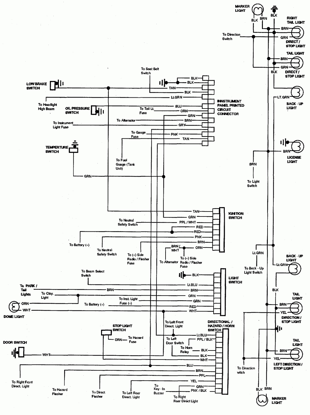
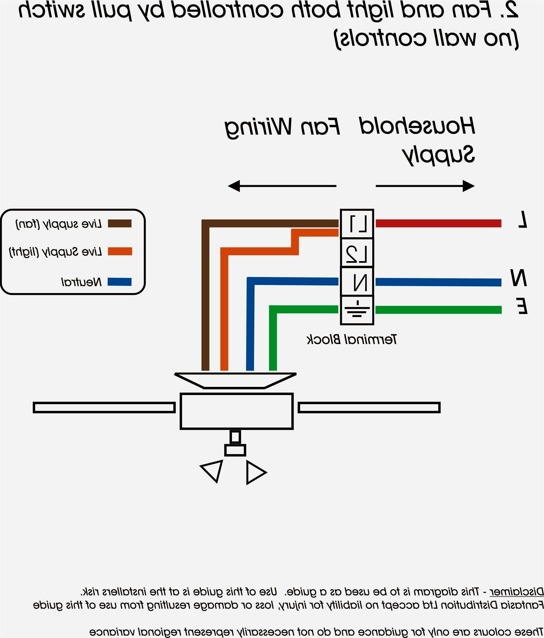
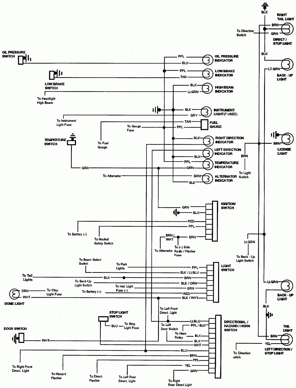
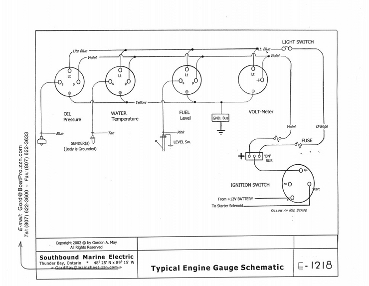
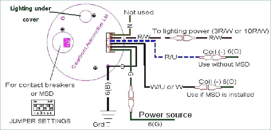
Introduction & Scope
Page 3
Electrical faults are among the most common challenges faced by technicians and engineers, whether in vehicles, automation panels, or electronic devices. They arise not only from layout flaws but also from vibration, corrosion, and heat. Over time, these factors weaken joints, loosen fasteners, and create inconsistent current routes that lead to intermittent faults.
In real-world troubleshooting, faults rarely appear as obvious failures. A loose ground may mimic a bad sensor, a oxidized terminal may cause random resets, and a concealed internal short can disable entire subsystems. Understanding why and how these faults occur forms the core of every repair process. When a circuit fails, the goal is not merely to replace components, but to trace the root cause and restore long-term reliability.
This section introduces typical fault categories found in wiring systemsbreaks, shorts, resistive joints, grounding faults, and oxidized connectorsand explains their observable effects. By learning the logic behind each failure type, technicians can analyze real-world signs more effectively. Continuity checks, voltage loss tests, and careful observation form the foundation of this diagnostic skill, allowing even complex wiring networks to be broken down logically.
Each fault tells a story about current behavior inside the system. A snapped wire leaves an open circuit; damaged insulation lets current escape from intended routes; an oxidized joint adds hidden resistance that wastes energy as heat. Recognizing these patterns turns abstract wiring diagrams into functional maps with measurable behavior.
In practice, diagnosing faults requires both instrumentation and intuition. Tools such as DMMs, scopes, and current probes provide numbers and traces, but experience and pattern recognition determine where to measure first and which values truly matter. Over time, skilled technicians learn to see electrical paths in their minds, predicting problem zones even before instruments confirm them.
Throughout this reference, fault diagnosis is treated not as a standalone process, but as a continuation of understanding circuit logic. By mastering the core principles of Ohms law, technicians can identify which part of the circuit violates those rules. That insight transforms troubleshooting from guesswork into structured analysis.
Whether you are servicing industrial panels, the same principles apply: trace the flow, confirm the ground, and let the measurements reveal the truth. Faults are not randomthey follow identifiable laws of resistance and flow. By learning to read that story within each wire, you turn chaos into clarity and restore systems to full reliability.
Safety and Handling
Page 4
Working safely around electrical systems requires discipline and consistency. First step: isolate the circuit, tag wires, and mark what was removed. Even low-voltage systems can store dangerous energy, so discharge capacitors before touching terminals. A wet, crowded work area multiplies risk, so control your environment first.
Good handling technique preserves both personal safety and equipment health. Make sure probes and grips are insulated and voltage-rated for the job. Do not force tight connectors or reuse corroded terminals — replace them with approved parts. Support harnesses with protective loom so they are not stressed or rubbed raw. Clean routing also reduces EMI and cross-talk in sensitive lines.
After repairs or modifications, verify all connections visually and electrically. Make sure ground paths are firm and protective housings are reattached. Only re-energize once insulation checks out and fuses match spec. Strict, repeatable safety practice is what separates a careful technician from a careless one.
Symbols & Abbreviations
Page 5
The icon tells you the function, and the label tells you the identity. A chassis ground icon and a labeled sensor/REF GND icon might look similar but are intentionally separate returns. Tying those grounds together can inject noise that ruins sensor accuracy in “Auto Meter U00ae 5232 Wiring Diagram”.
Abbreviations also tell you operating state and source. ACC means accessory power, RUN means ignition in run state, BATT or B+ means unswitched battery voltage, START means crank signal. Likewise you’ll read ABS CTRL, FAN CTRL, BODY ECU, INJ DRV — telling you which controller is in charge of which load in Wiring Diagram.
Whenever you splice or reroute wiring in 2025, keep the exact same label text. If you rename lines or reuse a label in the wrong place, the next technician may draw the wrong conclusion and cause a safety issue for http://mydiagram.online. Preserve the OEM naming and store change notes in https://http://mydiagram.online/auto-meter-u00ae-5232-wiring-diagram/ so future service on “Auto Meter U00ae 5232 Wiring Diagram” is auditable.
Wire Colors & Gauges
Page 6
The performance and safety of any electrical network rely on proper color codes and accurate wire gauge selection.
Color indicates purpose — such as power, ground, or communication — while gauge determines the amount of current that can pass through the wire without overheating.
Typically, red wires deliver power, black or brown provide grounding, yellow connects to switching or ignition circuits, and blue carries data or communication signals.
Following consistent color schemes allows engineers to identify circuits in “Auto Meter U00ae 5232 Wiring Diagram” quickly and avoid wiring mistakes.
Both color and gauge follow strict engineering logic that determines current flow and system integrity.
Gauge specification represents both the electrical rating and mechanical strength of the wire.
It determines current capacity, voltage drop, and how much mechanical stress the wire can endure.
Smaller gauge numbers equal thicker wires for high current, while larger numbers mean thinner wires for low current applications.
In Wiring Diagram, professionals follow ISO 6722, SAE J1128, or IEC 60228 standards to ensure consistency across automotive, industrial, and electronic systems.
Using the proper gauge helps control temperature, reduce resistance, and extend the lifespan of the electrical components in “Auto Meter U00ae 5232 Wiring Diagram”.
Gauge mismatches, even minor, result in electrical inefficiency and early component wear.
After installation, documentation guarantees the entire wiring process remains transparent and verifiable.
Document every color, gauge, and route clearly to maintain a reliable project record.
When rerouting or replacing wires, technicians should mark and record all changes in updated schematics.
Upload test data, continuity readings, and supporting images to http://mydiagram.online for review and auditing.
Adding project dates (2025) and source references (https://http://mydiagram.online/auto-meter-u00ae-5232-wiring-diagram/) ensures accountability and compliance with internal standards.
Thorough documentation turns ordinary wiring into a professional, auditable process that keeps “Auto Meter U00ae 5232 Wiring Diagram” safe and compliant.
Power Distribution Overview
Page 7
It is the organized mechanism that directs power from a central supply to every device and subsystem.
It maintains consistent voltage and current so each element of “Auto Meter U00ae 5232 Wiring Diagram” works efficiently.
A reliable distribution design maintains voltage balance, prevents excessive current draw, and protects circuits from failure.
Without proper planning, power fluctuations could result in overheating, poor performance, or permanent equipment damage.
In summary, power distribution is the hidden mechanism that keeps electrical systems safe, efficient, and predictable.
Developing a stable power distribution network requires precision and adherence to technical standards.
Cables, fuses, and terminals must match their current limits and environmental endurance levels.
Across Wiring Diagram, professionals rely on ISO 16750, IEC 61000, and SAE J1113 to achieve safe and standardized systems.
Cables carrying power and communication signals should be physically separated to avoid electromagnetic interference (EMI).
Protective and grounding elements should be accessible, well-marked, and resistant to wear.
By following these practices, “Auto Meter U00ae 5232 Wiring Diagram” achieves steady energy delivery and dependable performance.
After installation, thorough testing and documentation verify correct system operation.
Technicians should measure resistance, continuity, and voltage stability to verify proper performance.
Revisions must be documented on paper and electronically for traceability.
Inspection photos, reports, and voltage readings should be stored securely in http://mydiagram.online for long-term tracking.
Adding 2025 and https://http://mydiagram.online/auto-meter-u00ae-5232-wiring-diagram/ helps maintain transparency and proper documentation.
Comprehensive testing, documentation, and maintenance keep “Auto Meter U00ae 5232 Wiring Diagram” operating reliably for years to come.
Grounding Strategy
Page 8
Grounding is the key element that connects electrical systems to the earth, ensuring safety, stability, and long-term reliability.
It acts as a safeguard that prevents current surges, voltage transients, and unwanted static buildup.
Improper grounding in “Auto Meter U00ae 5232 Wiring Diagram” results in fluctuating voltage, noise issues, and potential component damage.
Good grounding minimizes these risks by providing a defined, low-resistance path for current to return safely to the ground.
Across Wiring Diagram, grounding is a mandatory practice for maintaining reliable and safe electrical systems.
A proper grounding system starts with careful planning and design.
Grounding design should account for soil resistance, expected current flow, and site conditions prior to setup.
Each connection must be mechanically strong, corrosion-resistant, and securely bonded to the main grounding network.
In Wiring Diagram, international standards such as IEC 60364 and IEEE 142 provide comprehensive guidance for grounding design and maintenance.
Grounding materials should be verified to withstand fault load without damage or performance loss.
By implementing these practices, “Auto Meter U00ae 5232 Wiring Diagram” ensures stable voltage reference, reduced interference, and safe system operation.
Periodic verification keeps the grounding system reliable and compliant with safety requirements.
Inspectors must test resistance, check joints, and document readings for consistent monitoring.
Any damaged or oxidized component must be cleaned, replaced, and retested immediately.
All inspection logs and test results must be documented and preserved for audit and traceability.
Annual or post-modification tests confirm system integrity and safety.
Consistent documentation and maintenance keep “Auto Meter U00ae 5232 Wiring Diagram” safe, efficient, and regulation-ready.
Connector Index & Pinout
Page 9
Auto Meter U00ae 5232 Wiring Diagram – Connector Index & Pinout Guide 2025
Crimping is the most common method for attaching wires to connector terminals in automotive and industrial systems. {A good crimp compresses the wire strands and terminal barrel together without cutting or deforming the conductor.|Proper crimping applies uniform pressure to achieve both s...
Using the correct crimping tool and die is essential for achieving manufacturer-specified compression levels. {Technicians should avoid using pliers or makeshift tools for crimping connectors.|Improper tools may crush or weaken the conductor instead of forming a stable joint.|Professional crimping pliers or hydraulic tools ensure consistent result...
Inspect each terminal for uniform compression and ensure no exposed wire strands are visible. {Practicing proper crimping methods leads to reliable electrical performance and reduced maintenance issues.|A correctly crimped connection enhances current flow and extends harness lifespan.|High-quality crimps are essential for stable ci...
Sensor Inputs
Page 10
Auto Meter U00ae 5232 Wiring Diagram Full Manual – Sensor Inputs Reference 2025
These sensors measure rotation or linear movement and convert it into electrical feedback. {Common types include throttle position sensors (TPS), camshaft sensors, and steering angle sensors.|Automotive applications rely heavily on position sensors for timing and efficiency.|Industri...
Most position sensors use potentiometric, Hall-effect, or inductive principles to generate signals. {Inductive sensors use electromagnetic coupling to detect metal target movement.|Each technology provides a specific output characteristic suitable for analog or digital interpretation.|Signal patterns from po...
A malfunctioning sensor might cause unstable idle, poor acceleration, or system fault codes. {Understanding position sensor operation improves calibration accuracy and ensures optimal system performance.|Proper testing of angular and linear sensors prevents false diagnosis and costly downtime.|Mastering position inp...
Actuator Outputs
Page 11
Auto Meter U00ae 5232 Wiring Diagram Full Manual – Sensor Inputs 2025
The Fuel Rail Pressure (FRP) sensor monitors fuel pressure within the fuel rail to ensure stable injection performance. {The ECU uses FRP input to adjust pump control, injector timing, and fuel trim.|Fuel pressure data enables automatic correction during load or temperature changes.|Stable FRP feedback ensures consistent engine po...
As pressure rises, the diaphragm inside the sensor deforms, altering resistance and voltage output. {A typical FRP sensor operates with a 5V reference and outputs between 0.5V (low pressure) and 4.5V (high pressure).|Voltage increases linearly as pressure builds up inside the fuel rail.|This direct feedback allows precise injector control for each cy...
A faulty FRP sensor can cause starting difficulty, poor acceleration, or rough idle. {Maintaining FRP sensor accuracy ensures safe pressure control and improved fuel economy.|Proper sensor calibration reduces risk of injector failure and unstable performance.|Understanding FRP feedback logic enhances fuel system diagnostics and reliabi...
Control Unit / Module
Page 12
Auto Meter U00ae 5232 Wiring Diagram – Actuator Outputs 2025
A relay allows a small control current to switch a larger load safely and efficiently. {When energized, the relay coil generates a magnetic field that pulls a contact arm, closing or opening the circuit.|This mechanism isolates the control side from the load side, protecting sensitive electronics.|The coil’s inductive ...
Electromechanical relays use moving contacts, while solid-state designs rely on semiconductor switching. {Automotive and industrial systems use relays for lamps, fans, motors, and heating elements.|Their ability to handle heavy loads makes them essential in both safety and automation applications.|Each relay type has unique advantages depending o...
Technicians should test relay function by checking coil resistance and verifying contact switching with a multimeter. {Proper relay diagnostics ensure circuit reliability and prevent overload damage.|Regular relay inspection extends service life and maintains stable actuator response.|Understanding relay behavior helps impro...
Communication Bus
Page 13
Serving as the primary digital nervous system of
the vehicle, the c…
High‑speed CAN
manages tasks such as torque modulation, ABS pulsation logic, active
stability correction, turbo vane actuation, injector phasing, and
drivetrain harmonizatio…
These disturbances manifest as
intermittent arbitration collapse, corrupted messaging frames, delayed
actuator response, abrupt sensor desynchronization, frozen module
states, unpr…
Protection: Fuse & Relay
Page 14
Fuse‑relay networks
are engineered as frontline safety components that absorb electrical
anomalies long before they compromise essential subsystems. Through
measured response rates and calibrated cutoff thresholds, they ensure
that power surges, short circuits, and intermittent faults remain
contained within predefined zones. This design philosophy prevents
chain‑reaction failures across distributed ECUs.
In modern architectures, relays handle repetitive activation
cycles, executing commands triggered by sensors or control software.
Their isolation capabilities reduce stress on low‑current circuits,
while fuses provide sacrificial protection whenever load spikes exceed
tolerance thresholds. Together they create a multi‑layer defense grid
adaptable to varying thermal and voltage demands.
Technicians often
diagnose issues by tracking inconsistent current delivery, noisy relay
actuation, unusual voltage fluctuations, or thermal discoloration on
fuse panels. Addressing these problems involves cleaning terminals,
reseating connectors, conditioning ground paths, and confirming load
consumption through controlled testing. Maintaining relay responsiveness
and fuse integrity ensures long‑term electrical stability.
Test Points & References
Page 15
Test points play a foundational role in Auto Meter U00ae 5232 Wiring Diagram 2025 Wiring Diagram by
providing load-simulation methodology distributed across the electrical
network. These predefined access nodes allow technicians to capture
stable readings without dismantling complex harness assemblies. By
exposing regulated supply rails, clean ground paths, and buffered signal
channels, test points simplify fault isolation and reduce diagnostic
time when tracking voltage drops, miscommunication between modules, or
irregular load behavior.
Using their strategic layout, test points enable
resistance-profile comparison, ensuring that faults related to thermal
drift, intermittent grounding, connector looseness, or voltage
instability are detected with precision. These checkpoints streamline
the troubleshooting workflow by eliminating unnecessary inspection of
unrelated harness branches and focusing attention on the segments most
likely to generate anomalies.
Common issues identified through test point evaluation include voltage
fluctuation, unstable ground return, communication dropouts, and erratic
sensor baselines. These symptoms often arise from corrosion, damaged
conductors, poorly crimped terminals, or EMI contamination along
high-frequency lines. Proper analysis requires oscilloscope tracing,
continuity testing, and resistance indexing to compare expected values
with real-time data.
Measurement Procedures
Page 16
Measurement procedures for Auto Meter U00ae 5232 Wiring Diagram 2025 Wiring Diagram begin with
load-simulation testing to establish accurate diagnostic foundations.
Technicians validate stable reference points such as regulator outputs,
ground planes, and sensor baselines before proceeding with deeper
analysis. This ensures reliable interpretation of electrical behavior
under different load and temperature conditions.
Technicians utilize these measurements to evaluate waveform stability,
load-simulation testing, and voltage behavior across multiple subsystem
domains. Comparing measured values against specifications helps identify
root causes such as component drift, grounding inconsistencies, or
load-induced fluctuations.
Frequent
anomalies identified during procedure-based diagnostics include ground
instability, periodic voltage collapse, digital noise interference, and
contact resistance spikes. Consistent documentation and repeated
sampling are essential to ensure accurate diagnostic conclusions.
Troubleshooting Guide
Page 17
Troubleshooting for Auto Meter U00ae 5232 Wiring Diagram 2025 Wiring Diagram begins with
reference-level comparison routines, ensuring the diagnostic process
starts with clarity and consistency. By checking basic system readiness,
technicians avoid deeper misinterpretations.
Field testing
incorporates switch-event behavior mapping, providing insight into
conditions that may not appear during bench testing. This highlights
environment‑dependent anomalies.
Certain failures can be traced to signal
reflections caused by inconsistent conductor impedance, distorting
digital communication pulses. High-resolution sampling helps highlight
reflection points along extended harness routes.
Common Fault Patterns
Page 18
Common fault patterns in Auto Meter U00ae 5232 Wiring Diagram 2025 Wiring Diagram frequently stem from
load-surge behavior during auxiliary accessory activation, a condition
that introduces irregular electrical behavior observable across multiple
subsystems. Early-stage symptoms are often subtle, manifesting as small
deviations in baseline readings or intermittent inconsistencies that
disappear as quickly as they appear. Technicians must therefore begin
diagnostics with broad-spectrum inspection, ensuring that fundamental
supply and return conditions are stable before interpreting more complex
indicators.
Patterns
linked to load-surge behavior during auxiliary accessory activation
frequently reveal themselves during active subsystem transitions, such
as ignition events, relay switching, or electronic module
initialization. The resulting irregularities—whether sudden voltage
dips, digital noise pulses, or inconsistent ground offset—are best
analyzed using waveform-capture tools that expose micro-level
distortions invisible to simple multimeter checks.
Persistent problems associated with load-surge behavior during
auxiliary accessory activation can escalate into module
desynchronization, sporadic sensor lockups, or complete loss of
communication on shared data lines. Technicians must examine wiring
paths for mechanical fatigue, verify grounding architecture stability,
assess connector tension, and confirm that supply rails remain steady
across temperature changes. Failure to address these foundational issues
often leads to repeated return visits.
Maintenance & Best Practices
Page 19
Maintenance and best practices for Auto Meter U00ae 5232 Wiring Diagram 2025 Wiring Diagram place
strong emphasis on vibration-induced wear countermeasures, ensuring that
electrical reliability remains consistent across all operating
conditions. Technicians begin by examining the harness environment,
verifying routing paths, and confirming that insulation remains intact.
This foundational approach prevents intermittent issues commonly
triggered by heat, vibration, or environmental contamination.
Technicians
analyzing vibration-induced wear countermeasures typically monitor
connector alignment, evaluate oxidation levels, and inspect wiring for
subtle deformations caused by prolonged thermal exposure. Protective
dielectric compounds and proper routing practices further contribute to
stable electrical pathways that resist mechanical stress and
environmental impact.
Failure
to maintain vibration-induced wear countermeasures can lead to cascading
electrical inconsistencies, including voltage drops, sensor signal
distortion, and sporadic subsystem instability. Long-term reliability
requires careful documentation, periodic connector service, and
verification of each branch circuit’s mechanical and electrical health
under both static and dynamic conditions.
Appendix & References
Page 20
The appendix for Auto Meter U00ae 5232 Wiring Diagram 2025 Wiring Diagram serves as a consolidated
reference hub focused on module identifier lookup tables, offering
technicians consistent terminology and structured documentation
practices. By collecting technical descriptors, abbreviations, and
classification rules into a single section, the appendix streamlines
interpretation of wiring layouts across diverse platforms. This ensures
that even complex circuit structures remain approachable through
standardized definitions and reference cues.
Documentation related to module identifier lookup tables frequently
includes structured tables, indexing lists, and lookup summaries that
reduce the need to cross‑reference multiple sources during system
evaluation. These entries typically describe connector types, circuit
categories, subsystem identifiers, and signal behavior definitions. By
keeping these details accessible, technicians can accelerate the
interpretation of wiring diagrams and troubleshoot with greater
accuracy.
Comprehensive references for module identifier lookup tables also
support long‑term documentation quality by ensuring uniform terminology
across service manuals, schematics, and diagnostic tools. When updates
occur—whether due to new sensors, revised standards, or subsystem
redesigns—the appendix remains the authoritative source for maintaining
alignment between engineering documentation and real‑world service
practices.
Deep Dive #1 - Signal Integrity & EMC
Page 21
Deep analysis of signal integrity in Auto Meter U00ae 5232 Wiring Diagram 2025 Wiring Diagram requires
investigating how frequency-domain interference impacting ECU logic
disrupts expected waveform performance across interconnected circuits.
As signals propagate through long harnesses, subtle distortions
accumulate due to impedance shifts, parasitic capacitance, and external
electromagnetic stress. This foundational assessment enables technicians
to understand where integrity loss begins and how it
evolves.
When frequency-domain interference impacting ECU logic occurs, signals
may experience phase delays, amplitude decay, or transient ringing
depending on harness composition and environmental exposure. Technicians
must review waveform transitions under varying thermal, load, and EMI
conditions. Tools such as high‑bandwidth oscilloscopes and frequency
analyzers reveal distortion patterns that remain hidden during static
measurements.
If frequency-domain
interference impacting ECU logic persists, cascading instability may
arise: intermittent communication, corrupt data frames, or erratic
control logic. Mitigation requires strengthening shielding layers,
rebalancing grounding networks, refining harness layout, and applying
proper termination strategies. These corrective steps restore signal
coherence under EMC stress.
Deep Dive #2 - Signal Integrity & EMC
Page 22
Advanced EMC evaluation in Auto Meter U00ae 5232 Wiring Diagram 2025 Wiring Diagram requires close
study of parasitic capacitance accumulating across connector arrays, a
phenomenon that can significantly compromise waveform predictability. As
systems scale toward higher bandwidth and greater sensitivity, minor
deviations in signal symmetry or reference alignment become amplified.
Understanding the initial conditions that trigger these distortions
allows technicians to anticipate system vulnerabilities before they
escalate.
When parasitic capacitance accumulating across connector arrays is
present, it may introduce waveform skew, in-band noise, or pulse
deformation that impacts the accuracy of both analog and digital
subsystems. Technicians must examine behavior under load, evaluate the
impact of switching events, and compare multi-frequency responses.
High‑resolution oscilloscopes and field probes reveal distortion
patterns hidden in time-domain measurements.
If left unresolved, parasitic capacitance
accumulating across connector arrays may trigger cascading disruptions
including frame corruption, false sensor readings, and irregular module
coordination. Effective countermeasures include controlled grounding,
noise‑filter deployment, re‑termination of critical paths, and
restructuring of cable routing to minimize electromagnetic coupling.
Deep Dive #3 - Signal Integrity & EMC
Page 23
A comprehensive
assessment of waveform stability requires understanding the effects of
magnetic-field drift altering low-frequency reference stability, a
factor capable of reshaping digital and analog signal profiles in subtle
yet impactful ways. This initial analysis phase helps technicians
identify whether distortions originate from physical harness geometry,
electromagnetic ingress, or internal module reference instability.
When magnetic-field drift altering low-frequency reference stability is
active within a vehicle’s electrical environment, technicians may
observe shift in waveform symmetry, rising-edge deformation, or delays
in digital line arbitration. These behaviors require examination under
multiple load states, including ignition operation, actuator cycling,
and high-frequency interference conditions. High-bandwidth oscilloscopes
and calibrated field probes reveal the hidden nature of such
distortions.
Prolonged exposure to magnetic-field drift altering low-frequency
reference stability may result in cumulative timing drift, erratic
communication retries, or persistent sensor inconsistencies. Mitigation
strategies include rebalancing harness impedance, reinforcing shielding
layers, deploying targeted EMI filters, optimizing grounding topology,
and refining cable routing to minimize exposure to EMC hotspots. These
measures restore signal clarity and long-term subsystem reliability.
Deep Dive #4 - Signal Integrity & EMC
Page 24
Evaluating advanced signal‑integrity interactions involves
examining the influence of ground-collapse instability under combined
thermal and EMI stress, a phenomenon capable of inducing significant
waveform displacement. These disruptions often develop gradually,
becoming noticeable only when communication reliability begins to drift
or subsystem timing loses coherence.
Systems experiencing
ground-collapse instability under combined thermal and EMI stress
frequently show instability during high‑demand operational windows, such
as engine load surges, rapid relay switching, or simultaneous
communication bursts. These events amplify embedded EMI vectors, making
spectral analysis essential for identifying the root interference mode.
If unresolved, ground-collapse instability
under combined thermal and EMI stress may escalate into severe
operational instability, corrupting digital frames or disrupting
tight‑timing control loops. Effective mitigation requires targeted
filtering, optimized termination schemes, strategic rerouting, and
harmonic suppression tailored to the affected frequency bands.
Deep Dive #5 - Signal Integrity & EMC
Page 25
Deep Dive #6 - Signal Integrity & EMC
Page 26
Signal behavior
under the influence of long-loop magnetic resonance forming under
dynamic chassis flex becomes increasingly unpredictable as electrical
environments evolve toward higher voltage domains, denser wiring
clusters, and more sensitive digital logic. Deep initial assessment
requires waveform sampling under various load conditions to establish a
reliable diagnostic baseline.
When long-loop magnetic resonance forming under dynamic chassis flex
occurs, technicians may observe inconsistent rise-times, amplitude
drift, complex ringing patterns, or intermittent jitter artifacts. These
symptoms often appear during subsystem interactions—such as inverter
ramps, actuator bursts, ADAS synchronization cycles, or ground-potential
fluctuations. High-bandwidth oscilloscopes and spectrum analyzers reveal
hidden distortion signatures.
Long-term exposure to long-loop magnetic resonance forming under
dynamic chassis flex may degrade subsystem coherence, trigger
inconsistent module responses, corrupt data frames, or produce rare but
severe system anomalies. Mitigation strategies include optimized
shielding architecture, targeted filter deployment, rerouting vulnerable
harness paths, reinforcing isolation barriers, and ensuring ground
uniformity throughout critical return networks.
Harness Layout Variant #1
Page 27
Designing Auto Meter U00ae 5232 Wiring Diagram 2025 Wiring Diagram harness layouts requires close
evaluation of routing elevation changes to avoid water accumulation
zones, an essential factor that influences both electrical performance
and mechanical longevity. Because harnesses interact with multiple
vehicle structures—panels, brackets, chassis contours—designers must
ensure that routing paths accommodate thermal expansion, vibration
profiles, and accessibility for maintenance.
During layout development, routing elevation changes to avoid water
accumulation zones can determine whether circuits maintain clean signal
behavior under dynamic operating conditions. Mechanical and electrical
domains intersect heavily in modern harness designs—routing angle,
bundling tightness, grounding alignment, and mounting intervals all
affect susceptibility to noise, wear, and heat.
Unchecked, routing elevation changes to avoid water accumulation
zones may lead to premature insulation wear, intermittent electrical
noise, connector stress, or routing interference with moving components.
Implementing balanced tensioning, precise alignment, service-friendly
positioning, and clear labeling mitigates long-term risk and enhances
system maintainability.
Harness Layout Variant #2
Page 28
Harness Layout Variant #2 for Auto Meter U00ae 5232 Wiring Diagram 2025 Wiring Diagram focuses on
weather-sealed grommet alignment blocking moisture paths, a structural
and electrical consideration that influences both reliability and
long-term stability. As modern vehicles integrate more electronic
modules, routing strategies must balance physical constraints with the
need for predictable signal behavior.
In real-world conditions, weather-sealed grommet alignment
blocking moisture paths determines the durability of the harness against
temperature cycles, motion-induced stress, and subsystem interference.
Careful arrangement of connectors, bundling layers, and anti-chafe
supports helps maintain reliable performance even in high-demand chassis
zones.
Managing weather-sealed grommet alignment blocking moisture paths
effectively results in improved robustness, simplified maintenance, and
enhanced overall system stability. Engineers apply isolation rules,
structural reinforcement, and optimized routing logic to produce a
layout capable of sustaining long-term operational loads.
Harness Layout Variant #3
Page 29
Harness Layout Variant #3 for Auto Meter U00ae 5232 Wiring Diagram 2025 Wiring Diagram focuses on
service‑optimized harness loops for diagnostic accessibility, an
essential structural and functional element that affects reliability
across multiple vehicle zones. Modern platforms require routing that
accommodates mechanical constraints while sustaining consistent
electrical behavior and long-term durability.
In real-world operation, service‑optimized
harness loops for diagnostic accessibility determines how the harness
responds to thermal cycling, chassis motion, subsystem vibration, and
environmental elements. Proper connector staging, strategic bundling,
and controlled curvature help maintain stable performance even in
aggressive duty cycles.
Managing service‑optimized harness loops for diagnostic accessibility
effectively ensures robust, serviceable, and EMI‑resistant harness
layouts. Engineers rely on optimized routing classifications, grounding
structures, anti‑wear layers, and anchoring intervals to produce a
layout that withstands long-term operational loads.
Harness Layout Variant #4
Page 30
The architectural
approach for this variant prioritizes roof-line harness suspension minimizing sag and rattle, focusing on
service access, electrical noise reduction, and long-term durability. Engineers balance bundle compactness
with proper signal separation to avoid EMI coupling while keeping the routing footprint efficient.
In real-world operation, roof-
line harness suspension minimizing sag and rattle affects signal quality near actuators, motors, and
infotainment modules. Cable elevation, branch sequencing, and anti-chafe barriers reduce premature wear. A
combination of elastic tie-points, protective sleeves, and low-profile clips keeps bundles orderly yet
flexible under dynamic loads.
Proper control of roof-line harness suspension minimizing sag and rattle
minimizes moisture intrusion, terminal corrosion, and cross-path noise. Best practices include labeled
manufacturing references, measured service loops, and HV/LV clearance audits. When components are updated,
route documentation and measurement points simplify verification without dismantling the entire assembly.
Diagnostic Flowchart #1
Page 31
The initial stage of
Diagnostic Flowchart #1 emphasizes isolated module wake‑sequence evaluation for timing anomalies, ensuring
that the most foundational electrical references are validated before branching into deeper subsystem
evaluation. This reduces misdirection caused by surface‑level symptoms. As diagnostics progress, isolated module wake‑sequence evaluation for timing
anomalies becomes a critical branch factor influencing decisions relating to grounding integrity, power
sequencing, and network communication paths. This structured logic ensures accuracy even when symptoms appear
scattered. If isolated module
wake‑sequence evaluation for timing anomalies is not thoroughly validated, subtle faults can cascade into
widespread subsystem instability. Reinforcing each decision node with targeted measurements improves long‑term
reliability and prevents misdiagnosis.
Diagnostic Flowchart #2
Page 32
Diagnostic Flowchart #2 for Auto Meter U00ae 5232 Wiring Diagram 2025 Wiring Diagram begins by addressing flow‑based elimination of actuator
driver inconsistencies, establishing a clear entry point for isolating electrical irregularities that may
appear intermittent or load‑dependent. Technicians rely on this structured starting node to avoid
misinterpretation of symptoms caused by secondary effects. As the diagnostic flow advances,
flow‑based elimination of actuator driver inconsistencies shapes the logic of each decision node. Mid‑stage
evaluation involves segmenting power, ground, communication, and actuation pathways to progressively narrow
down fault origins. This stepwise refinement is crucial for revealing timing‑related and load‑sensitive
anomalies. Completing the flow ensures that flow‑based elimination of actuator driver
inconsistencies is validated under multiple operating conditions, reducing the likelihood of recurring issues.
The resulting diagnostic trail provides traceable documentation that improves future troubleshooting
accuracy.
Diagnostic Flowchart #3
Page 33
The first branch of Diagnostic Flowchart #3 prioritizes latency‑shift analysis during Ethernet
frame bursts, ensuring foundational stability is confirmed before deeper subsystem exploration. This prevents
misdirection caused by intermittent or misleading electrical behavior. As the flowchart progresses,
latency‑shift analysis during Ethernet frame bursts defines how mid‑stage decisions are segmented. Technicians
sequentially eliminate power, ground, communication, and actuation domains while interpreting timing shifts,
signal drift, or misalignment across related circuits. Once latency‑shift analysis during Ethernet frame bursts is fully evaluated across multiple load
states, the technician can confirm or dismiss entire fault categories. This structured approach enhances
long‑term reliability and reduces repeat troubleshooting visits.
Diagnostic Flowchart #4
Page 34
Diagnostic Flowchart #4 for Auto Meter U00ae 5232 Wiring Diagram 2025
Wiring Diagram focuses on structured recovery mapping for intermittent CAN desync, laying the foundation for a
structured fault‑isolation path that eliminates guesswork and reduces unnecessary component swapping. The
first stage examines core references, voltage stability, and baseline communication health to determine
whether the issue originates in the primary network layer or in a secondary subsystem. Technicians follow a
branched decision flow that evaluates signal symmetry, grounding patterns, and frame stability before
advancing into deeper diagnostic layers. As the evaluation continues, structured recovery mapping for intermittent CAN
desync becomes the controlling factor for mid‑level branch decisions. This includes correlating waveform
alignment, identifying momentary desync signatures, and interpreting module wake‑timing conflicts. By dividing
the diagnostic pathway into focused electrical domains—power delivery, grounding integrity, communication
architecture, and actuator response—the flowchart ensures that each stage removes entire categories of faults
with minimal overlap. This structured segmentation accelerates troubleshooting and increases diagnostic
precision. The final stage ensures that structured recovery mapping for intermittent CAN desync is
validated under multiple operating conditions, including thermal stress, load spikes, vibration, and state
transitions. These controlled stress points help reveal hidden instabilities that may not appear during static
testing. Completing all verification nodes ensures long‑term stability, reducing the likelihood of recurring
issues and enabling technicians to document clear, repeatable steps for future diagnostics.
Case Study #1 - Real-World Failure
Page 35
Case Study #1 for Auto Meter U00ae 5232 Wiring Diagram 2025 Wiring Diagram examines a real‑world failure involving random ECU resets linked to
micro‑cracks in PCB solder joints. The issue first appeared as an intermittent symptom that did not trigger a
consistent fault code, causing technicians to suspect unrelated components. Early observations highlighted
irregular electrical behavior, such as momentary signal distortion, delayed module responses, or fluctuating
reference values. These symptoms tended to surface under specific thermal, vibration, or load conditions,
making replication difficult during static diagnostic tests. Further investigation into random ECU resets
linked to micro‑cracks in PCB solder joints required systematic measurement across power distribution paths,
grounding nodes, and communication channels. Technicians used targeted diagnostic flowcharts to isolate
variables such as voltage drop, EMI exposure, timing skew, and subsystem desynchronization. By reproducing the
fault under controlled conditions—applying heat, inducing vibration, or simulating high load—they identified
the precise moment the failure manifested. This structured process eliminated multiple potential contributors,
narrowing the fault domain to a specific harness segment, component group, or module logic pathway. The
confirmed cause tied to random ECU resets linked to micro‑cracks in PCB solder joints allowed technicians to
implement the correct repair, whether through component replacement, harness restoration, recalibration, or
module reprogramming. After corrective action, the system was subjected to repeated verification cycles to
ensure long‑term stability under all operating conditions. Documenting the failure pattern and diagnostic
sequence provided valuable reference material for similar future cases, reducing diagnostic time and
preventing unnecessary part replacement.
Case Study #2 - Real-World Failure
Page 36
Case Study #2 for Auto Meter U00ae 5232 Wiring Diagram 2025 Wiring Diagram examines a real‑world failure involving ECU misinterpretation of
torque signals during transient EMI bursts. The issue presented itself with intermittent symptoms that varied
depending on temperature, load, or vehicle motion. Technicians initially observed irregular system responses,
inconsistent sensor readings, or sporadic communication drops. Because the symptoms did not follow a
predictable pattern, early attempts at replication were unsuccessful, leading to misleading assumptions about
unrelated subsystems. A detailed investigation into ECU misinterpretation of torque signals during transient
EMI bursts required structured diagnostic branching that isolated power delivery, ground stability,
communication timing, and sensor integrity. Using controlled diagnostic tools, technicians applied thermal
load, vibration, and staged electrical demand to recreate the failure in a measurable environment. Progressive
elimination of subsystem groups—ECUs, harness segments, reference points, and actuator pathways—helped reveal
how the failure manifested only under specific operating thresholds. This systematic breakdown prevented
misdiagnosis and reduced unnecessary component swaps. Once the cause linked to ECU misinterpretation of
torque signals during transient EMI bursts was confirmed, the corrective action involved either reconditioning
the harness, replacing the affected component, reprogramming module firmware, or adjusting calibration
parameters. Post‑repair validation cycles were performed under varied conditions to ensure long‑term
reliability and prevent future recurrence. Documentation of the failure characteristics, diagnostic sequence,
and final resolution now serves as a reference for addressing similar complex faults more efficiently.
Case Study #3 - Real-World Failure
Page 37
Case Study #3 for Auto Meter U00ae 5232 Wiring Diagram 2025 Wiring Diagram focuses on a real‑world failure involving mass‑airflow sensor
non‑linearity after extended turbulence exposure. Technicians first observed erratic system behavior,
including fluctuating sensor values, delayed control responses, and sporadic communication warnings. These
symptoms appeared inconsistently, often only under specific temperature, load, or vibration conditions. Early
troubleshooting attempts failed to replicate the issue reliably, creating the impression of multiple unrelated
subsystem faults rather than a single root cause. To investigate mass‑airflow sensor non‑linearity after
extended turbulence exposure, a structured diagnostic approach was essential. Technicians conducted staged
power and ground validation, followed by controlled stress testing that included thermal loading, vibration
simulation, and alternating electrical demand. This method helped reveal the precise operational threshold at
which the failure manifested. By isolating system domains—communication networks, power rails, grounding
nodes, and actuator pathways—the diagnostic team progressively eliminated misleading symptoms and narrowed the
problem to a specific failure mechanism. After identifying the underlying cause tied to mass‑airflow sensor
non‑linearity after extended turbulence exposure, technicians carried out targeted corrective actions such as
replacing compromised components, restoring harness integrity, updating ECU firmware, or recalibrating
affected subsystems. Post‑repair validation cycles confirmed stable performance across all operating
conditions. The documented diagnostic path and resolution now serve as a repeatable reference for addressing
similar failures with greater speed and accuracy.
Case Study #4 - Real-World Failure
Page 38
Case Study #4 for Auto Meter U00ae 5232 Wiring Diagram 2025 Wiring Diagram examines a high‑complexity real‑world failure involving air‑fuel
control deviation caused by MAP sensor saturation. The issue manifested across multiple subsystems
simultaneously, creating an array of misleading symptoms ranging from inconsistent module responses to
distorted sensor feedback and intermittent communication warnings. Initial diagnostics were inconclusive due
to the fault’s dependency on vibration, thermal shifts, or rapid load changes. These fluctuating conditions
allowed the failure to remain dormant during static testing, pushing technicians to explore deeper system
interactions that extended beyond conventional troubleshooting frameworks. To investigate air‑fuel control
deviation caused by MAP sensor saturation, technicians implemented a layered diagnostic workflow combining
power‑rail monitoring, ground‑path validation, EMI tracing, and logic‑layer analysis. Stress tests were
applied in controlled sequences to recreate the precise environment in which the instability surfaced—often
requiring synchronized heat, vibration, and electrical load modulation. By isolating communication domains,
verifying timing thresholds, and comparing analog sensor behavior under dynamic conditions, the diagnostic
team uncovered subtle inconsistencies that pointed toward deeper system‑level interactions rather than
isolated component faults. After confirming the root mechanism tied to air‑fuel control deviation caused by
MAP sensor saturation, corrective action involved component replacement, harness reconditioning, ground‑plane
reinforcement, or ECU firmware restructuring depending on the failure’s nature. Technicians performed
post‑repair endurance tests that included repeated thermal cycling, vibration exposure, and electrical stress
to guarantee long‑term system stability. Thorough documentation of the analysis method, failure pattern, and
final resolution now serves as a highly valuable reference for identifying and mitigating similar
high‑complexity failures in the future.
Case Study #5 - Real-World Failure
Page 39
Case Study #5 for Auto Meter U00ae 5232 Wiring Diagram 2025 Wiring Diagram investigates a complex real‑world failure involving severe
ground‑reference divergence across multi‑module clusters. The issue initially presented as an inconsistent
mixture of delayed system reactions, irregular sensor values, and sporadic communication disruptions. These
events tended to appear under dynamic operational conditions—such as elevated temperatures, sudden load
transitions, or mechanical vibration—which made early replication attempts unreliable. Technicians encountered
symptoms occurring across multiple modules simultaneously, suggesting a deeper systemic interaction rather
than a single isolated component failure. During the investigation of severe ground‑reference divergence
across multi‑module clusters, a multi‑layered diagnostic workflow was deployed. Technicians performed
sequential power‑rail mapping, ground‑plane verification, and high‑frequency noise tracing to detect hidden
instabilities. Controlled stress testing—including targeted heat application, induced vibration, and variable
load modulation—was carried out to reproduce the failure consistently. The team methodically isolated
subsystem domains such as communication networks, analog sensor paths, actuator control logic, and module
synchronization timing. This progressive elimination approach identified critical operational thresholds where
the failure reliably emerged. After determining the underlying mechanism tied to severe ground‑reference
divergence across multi‑module clusters, technicians carried out corrective actions that ranged from harness
reconditioning and connector reinforcement to firmware restructuring and recalibration of affected modules.
Post‑repair validation involved repeated cycles of vibration, thermal stress, and voltage fluctuation to
ensure long‑term stability and eliminate the possibility of recurrence. The documented resolution pathway now
serves as an advanced reference model for diagnosing similarly complex failures across modern vehicle
platforms.
Case Study #6 - Real-World Failure
Page 40
Case Study #6 for Auto Meter U00ae 5232 Wiring Diagram 2025 Wiring Diagram examines a complex real‑world failure involving ECU logic deadlock
initiated by ripple‑induced reference collapse. Symptoms emerged irregularly, with clustered faults appearing
across unrelated modules, giving the impression of multiple simultaneous subsystem failures. These
irregularities depended strongly on vibration, temperature shifts, or abrupt electrical load changes, making
the issue difficult to reproduce during initial diagnostic attempts. Technicians noted inconsistent sensor
feedback, communication delays, and momentary power‑rail fluctuations that persisted without generating
definitive fault codes. The investigation into ECU logic deadlock initiated by ripple‑induced reference
collapse required a multi‑layer diagnostic strategy combining signal‑path tracing, ground stability
assessment, and high‑frequency noise evaluation. Technicians executed controlled stress tests—including
thermal cycling, vibration induction, and staged electrical loading—to reveal the exact thresholds at which
the fault manifested. Using structured elimination across harness segments, module clusters, and reference
nodes, they isolated subtle timing deviations, analog distortions, or communication desynchronization that
pointed toward a deeper systemic failure mechanism rather than isolated component malfunction. Once ECU logic
deadlock initiated by ripple‑induced reference collapse was identified as the root failure mechanism, targeted
corrective measures were implemented. These included harness reinforcement, connector replacement, firmware
restructuring, recalibration of key modules, or ground‑path reconfiguration depending on the nature of the
instability. Post‑repair endurance runs with repeated vibration, heat cycles, and voltage stress ensured
long‑term reliability. Documentation of the diagnostic sequence and recovery pathway now provides a vital
reference for detecting and resolving similarly complex failures more efficiently in future service
operations.
Hands-On Lab #1 - Measurement Practice
Page 41
Hands‑On Lab #1 for Auto Meter U00ae 5232 Wiring Diagram 2025 Wiring Diagram focuses on noise‑floor measurement for analog sensor lines
exposed to EMI. This exercise teaches technicians how to perform structured diagnostic measurements using
multimeters, oscilloscopes, current probes, and differential tools. The initial phase emphasizes establishing
a stable baseline by checking reference voltages, verifying continuity, and confirming ground integrity. These
foundational steps ensure that subsequent measurements reflect true system behavior rather than secondary
anomalies introduced by poor probing technique or unstable electrical conditions. During the measurement
routine for noise‑floor measurement for analog sensor lines exposed to EMI, technicians analyze dynamic
behavior by applying controlled load, capturing waveform transitions, and monitoring subsystem responses. This
includes observing timing shifts, duty‑cycle changes, ripple patterns, or communication irregularities. By
replicating real operating conditions—thermal changes, vibration, or electrical demand spikes—technicians gain
insight into how the system behaves under stress. This approach allows deeper interpretation of patterns that
static readings cannot reveal. After completing the procedure for noise‑floor measurement for analog sensor
lines exposed to EMI, results are documented with precise measurement values, waveform captures, and
interpretation notes. Technicians compare the observed data with known good references to determine whether
performance falls within acceptable thresholds. The collected information not only confirms system health but
also builds long‑term diagnostic proficiency by helping technicians recognize early indicators of failure and
understand how small variations can evolve into larger issues.
Hands-On Lab #2 - Measurement Practice
Page 42
Hands‑On Lab #2 for Auto Meter U00ae 5232 Wiring Diagram 2025 Wiring Diagram focuses on differential probing of twisted‑pair communication
lines. This practical exercise expands technician measurement skills by emphasizing accurate probing
technique, stable reference validation, and controlled test‑environment setup. Establishing baseline
readings—such as reference ground, regulated voltage output, and static waveform characteristics—is essential
before any dynamic testing occurs. These foundational checks prevent misinterpretation caused by poor tool
placement, floating grounds, or unstable measurement conditions. During the procedure for differential
probing of twisted‑pair communication lines, technicians simulate operating conditions using thermal stress,
vibration input, and staged subsystem loading. Dynamic measurements reveal timing inconsistencies, amplitude
drift, duty‑cycle changes, communication irregularities, or nonlinear sensor behavior. Oscilloscopes, current
probes, and differential meters are used to capture high‑resolution waveform data, enabling technicians to
identify subtle deviations that static multimeter readings cannot detect. Emphasis is placed on interpreting
waveform shape, slope, ripple components, and synchronization accuracy across interacting modules. After
completing the measurement routine for differential probing of twisted‑pair communication lines, technicians
document quantitative findings—including waveform captures, voltage ranges, timing intervals, and noise
signatures. The recorded results are compared to known‑good references to determine subsystem health and
detect early‑stage degradation. This structured approach not only builds diagnostic proficiency but also
enhances a technician’s ability to predict emerging faults before they manifest as critical failures,
strengthening long‑term reliability of the entire system.
Hands-On Lab #3 - Measurement Practice
Page 43
Hands‑On Lab #3 for Auto Meter U00ae 5232 Wiring Diagram 2025 Wiring Diagram focuses on injector solenoid coil resistance drift analysis. This
exercise trains technicians to establish accurate baseline measurements before introducing dynamic stress.
Initial steps include validating reference grounds, confirming supply‑rail stability, and ensuring probing
accuracy. These fundamentals prevent distorted readings and help ensure that waveform captures or voltage
measurements reflect true electrical behavior rather than artifacts caused by improper setup or tool noise.
During the diagnostic routine for injector solenoid coil resistance drift analysis, technicians apply
controlled environmental adjustments such as thermal cycling, vibration, electrical loading, and communication
traffic modulation. These dynamic inputs help expose timing drift, ripple growth, duty‑cycle deviations,
analog‑signal distortion, or module synchronization errors. Oscilloscopes, clamp meters, and differential
probes are used extensively to capture transitional data that cannot be observed with static measurements
alone. After completing the measurement sequence for injector solenoid coil resistance drift analysis,
technicians document waveform characteristics, voltage ranges, current behavior, communication timing
variations, and noise patterns. Comparison with known‑good datasets allows early detection of performance
anomalies and marginal conditions. This structured measurement methodology strengthens diagnostic confidence
and enables technicians to identify subtle degradation before it becomes a critical operational failure.
Hands-On Lab #4 - Measurement Practice
Page 44
Hands‑On Lab #4 for Auto Meter U00ae 5232 Wiring Diagram 2025 Wiring Diagram focuses on module wake‑signal propagation delay evaluation. This
laboratory exercise builds on prior modules by emphasizing deeper measurement accuracy, environment control,
and test‑condition replication. Technicians begin by validating stable reference grounds, confirming regulated
supply integrity, and preparing measurement tools such as oscilloscopes, current probes, and high‑bandwidth
differential probes. Establishing clean baselines ensures that subsequent waveform analysis is meaningful and
not influenced by tool noise or ground drift. During the measurement procedure for module wake‑signal
propagation delay evaluation, technicians introduce dynamic variations including staged electrical loading,
thermal cycling, vibration input, or communication‑bus saturation. These conditions reveal real‑time behaviors
such as timing drift, amplitude instability, duty‑cycle deviation, ripple formation, or synchronization loss
between interacting modules. High‑resolution waveform capture enables technicians to observe subtle waveform
features—slew rate, edge deformation, overshoot, undershoot, noise bursts, and harmonic artifacts. Upon
completing the assessment for module wake‑signal propagation delay evaluation, all findings are documented
with waveform snapshots, quantitative measurements, and diagnostic interpretations. Comparing collected data
with verified reference signatures helps identify early‑stage degradation, marginal component performance, and
hidden instability trends. This rigorous measurement framework strengthens diagnostic precision and ensures
that technicians can detect complex electrical issues long before they evolve into system‑wide failures.
Hands-On Lab #5 - Measurement Practice
Page 45
Hands‑On Lab #5 for Auto Meter U00ae 5232 Wiring Diagram 2025 Wiring Diagram focuses on real‑time voltage sag tracing during rapid subsystem
activation. The session begins with establishing stable measurement baselines by validating grounding
integrity, confirming supply‑rail stability, and ensuring probe calibration. These steps prevent erroneous
readings and ensure that all waveform captures accurately reflect subsystem behavior. High‑accuracy tools such
as oscilloscopes, clamp meters, and differential probes are prepared to avoid ground‑loop artifacts or
measurement noise. During the procedure for real‑time voltage sag tracing during rapid subsystem activation,
technicians introduce dynamic test conditions such as controlled load spikes, thermal cycling, vibration, and
communication saturation. These deliberate stresses expose real‑time effects like timing jitter, duty‑cycle
deformation, signal‑edge distortion, ripple growth, and cross‑module synchronization drift. High‑resolution
waveform captures allow technicians to identify anomalies that static tests cannot reveal, such as harmonic
noise, high‑frequency interference, or momentary dropouts in communication signals. After completing all
measurements for real‑time voltage sag tracing during rapid subsystem activation, technicians document voltage
ranges, timing intervals, waveform shapes, noise signatures, and current‑draw curves. These results are
compared against known‑good references to identify early‑stage degradation or marginal component behavior.
Through this structured measurement framework, technicians strengthen diagnostic accuracy and develop
long‑term proficiency in detecting subtle trends that could lead to future system failures.
Hands-On Lab #6 - Measurement Practice
Page 46
Hands‑On Lab #6 for Auto Meter U00ae 5232 Wiring Diagram 2025 Wiring Diagram focuses on ground‑path impedance drift evaluation across body
structural nodes. This advanced laboratory module strengthens technician capability in capturing high‑accuracy
diagnostic measurements. The session begins with baseline validation of ground reference integrity, regulated
supply behavior, and probe calibration. Ensuring noise‑free, stable baselines prevents waveform distortion and
guarantees that all readings reflect genuine subsystem behavior rather than tool‑induced artifacts or
grounding errors. Technicians then apply controlled environmental modulation such as thermal shocks,
vibration exposure, staged load cycling, and communication traffic saturation. These dynamic conditions reveal
subtle faults including timing jitter, duty‑cycle deformation, amplitude fluctuation, edge‑rate distortion,
harmonic buildup, ripple amplification, and module synchronization drift. High‑bandwidth oscilloscopes,
differential probes, and current clamps are used to capture transient behaviors invisible to static multimeter
measurements. Following completion of the measurement routine for ground‑path impedance drift evaluation
across body structural nodes, technicians document waveform shapes, voltage windows, timing offsets, noise
signatures, and current patterns. Results are compared against validated reference datasets to detect
early‑stage degradation or marginal component behavior. By mastering this structured diagnostic framework,
technicians build long‑term proficiency and can identify complex electrical instabilities before they lead to
full system failure.
Checklist & Form #1 - Quality Verification
Page 47
Checklist & Form #1 for Auto Meter U00ae 5232 Wiring Diagram 2025 Wiring Diagram focuses on connector tension and corrosion‑risk inspection
checklist. This verification document provides a structured method for ensuring electrical and electronic
subsystems meet required performance standards. Technicians begin by confirming baseline conditions such as
stable reference grounds, regulated voltage supplies, and proper connector engagement. Establishing these
baselines prevents false readings and ensures all subsequent measurements accurately reflect system behavior.
During completion of this form for connector tension and corrosion‑risk inspection checklist, technicians
evaluate subsystem performance under both static and dynamic conditions. This includes validating signal
integrity, monitoring voltage or current drift, assessing noise susceptibility, and confirming communication
stability across modules. Checkpoints guide technicians through critical inspection areas—sensor accuracy,
actuator responsiveness, bus timing, harness quality, and module synchronization—ensuring each element is
validated thoroughly using industry‑standard measurement practices. After filling out the checklist for
connector tension and corrosion‑risk inspection checklist, all results are documented, interpreted, and
compared against known‑good reference values. This structured documentation supports long‑term reliability
tracking, facilitates early detection of emerging issues, and strengthens overall system quality. The
completed form becomes part of the quality‑assurance record, ensuring compliance with technical standards and
providing traceability for future diagnostics.
Checklist & Form #2 - Quality Verification
Page 48
Checklist & Form #2 for Auto Meter U00ae 5232 Wiring Diagram 2025 Wiring Diagram focuses on thermal‑cycle durability assessment for sensitive
components. This structured verification tool guides technicians through a comprehensive evaluation of
electrical system readiness. The process begins by validating baseline electrical conditions such as stable
ground references, regulated supply integrity, and secure connector engagement. Establishing these
fundamentals ensures that all subsequent diagnostic readings reflect true subsystem behavior rather than
interference from setup or tooling issues. While completing this form for thermal‑cycle durability assessment
for sensitive components, technicians examine subsystem performance across both static and dynamic conditions.
Evaluation tasks include verifying signal consistency, assessing noise susceptibility, monitoring thermal
drift effects, checking communication timing accuracy, and confirming actuator responsiveness. Each checkpoint
guides the technician through critical areas that contribute to overall system reliability, helping ensure
that performance remains within specification even during operational stress. After documenting all required
fields for thermal‑cycle durability assessment for sensitive components, technicians interpret recorded
measurements and compare them against validated reference datasets. This documentation provides traceability,
supports early detection of marginal conditions, and strengthens long‑term quality control. The completed
checklist forms part of the official audit trail and contributes directly to maintaining electrical‑system
reliability across the vehicle platform.
Checklist & Form #3 - Quality Verification
Page 49
Checklist & Form #3 for Auto Meter U00ae 5232 Wiring Diagram 2025 Wiring Diagram covers ripple and transient‑spike tolerance report. This
verification document ensures that every subsystem meets electrical and operational requirements before final
approval. Technicians begin by validating fundamental conditions such as regulated supply voltage, stable
ground references, and secure connector seating. These baseline checks eliminate misleading readings and
ensure that all subsequent measurements represent true subsystem behavior without tool‑induced artifacts.
While completing this form for ripple and transient‑spike tolerance report, technicians review subsystem
behavior under multiple operating conditions. This includes monitoring thermal drift, verifying
signal‑integrity consistency, checking module synchronization, assessing noise susceptibility, and confirming
actuator responsiveness. Structured checkpoints guide technicians through critical categories such as
communication timing, harness integrity, analog‑signal quality, and digital logic performance to ensure
comprehensive verification. After documenting all required values for ripple and transient‑spike tolerance
report, technicians compare collected data with validated reference datasets. This ensures compliance with
design tolerances and facilitates early detection of marginal or unstable behavior. The completed form becomes
part of the permanent quality‑assurance record, supporting traceability, long‑term reliability monitoring, and
efficient future diagnostics.
Checklist & Form #4 - Quality Verification
Page 50
Checklist & Form #4 for Auto Meter U00ae 5232 Wiring Diagram 2025 Wiring Diagram documents network‑timing coherence verification across
CAN/LIN layers. This final‑stage verification tool ensures that all electrical subsystems meet operational,
structural, and diagnostic requirements prior to release. Technicians begin by confirming essential baseline
conditions such as reference‑ground accuracy, stabilized supply rails, connector engagement integrity, and
sensor readiness. Proper baseline validation eliminates misleading measurements and guarantees that subsequent
inspection results reflect authentic subsystem behavior. While completing this verification form for
network‑timing coherence verification across CAN/LIN layers, technicians evaluate subsystem stability under
controlled stress conditions. This includes monitoring thermal drift, confirming actuator consistency,
validating signal integrity, assessing network‑timing alignment, verifying resistance and continuity
thresholds, and checking noise immunity levels across sensitive analog and digital pathways. Each checklist
point is structured to guide the technician through areas that directly influence long‑term reliability and
diagnostic predictability. After completing the form for network‑timing coherence verification across CAN/LIN
layers, technicians document measurement results, compare them with approved reference profiles, and certify
subsystem compliance. This documentation provides traceability, aids in trend analysis, and ensures adherence
to quality‑assurance standards. The completed form becomes part of the permanent electrical validation record,
supporting reliable operation throughout the vehicle’s lifecycle.