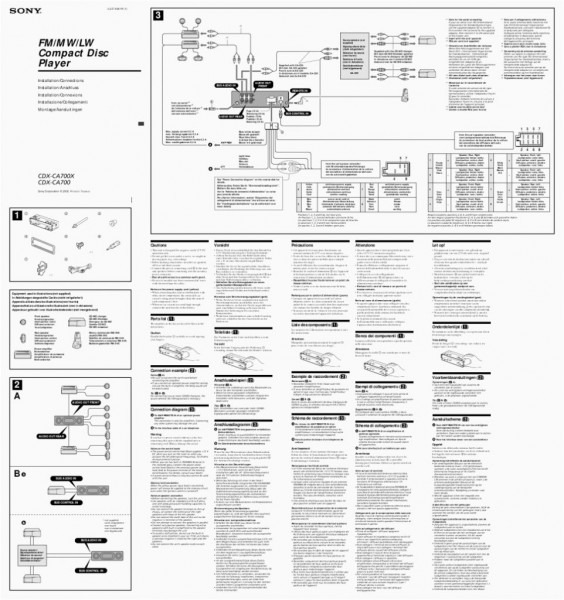
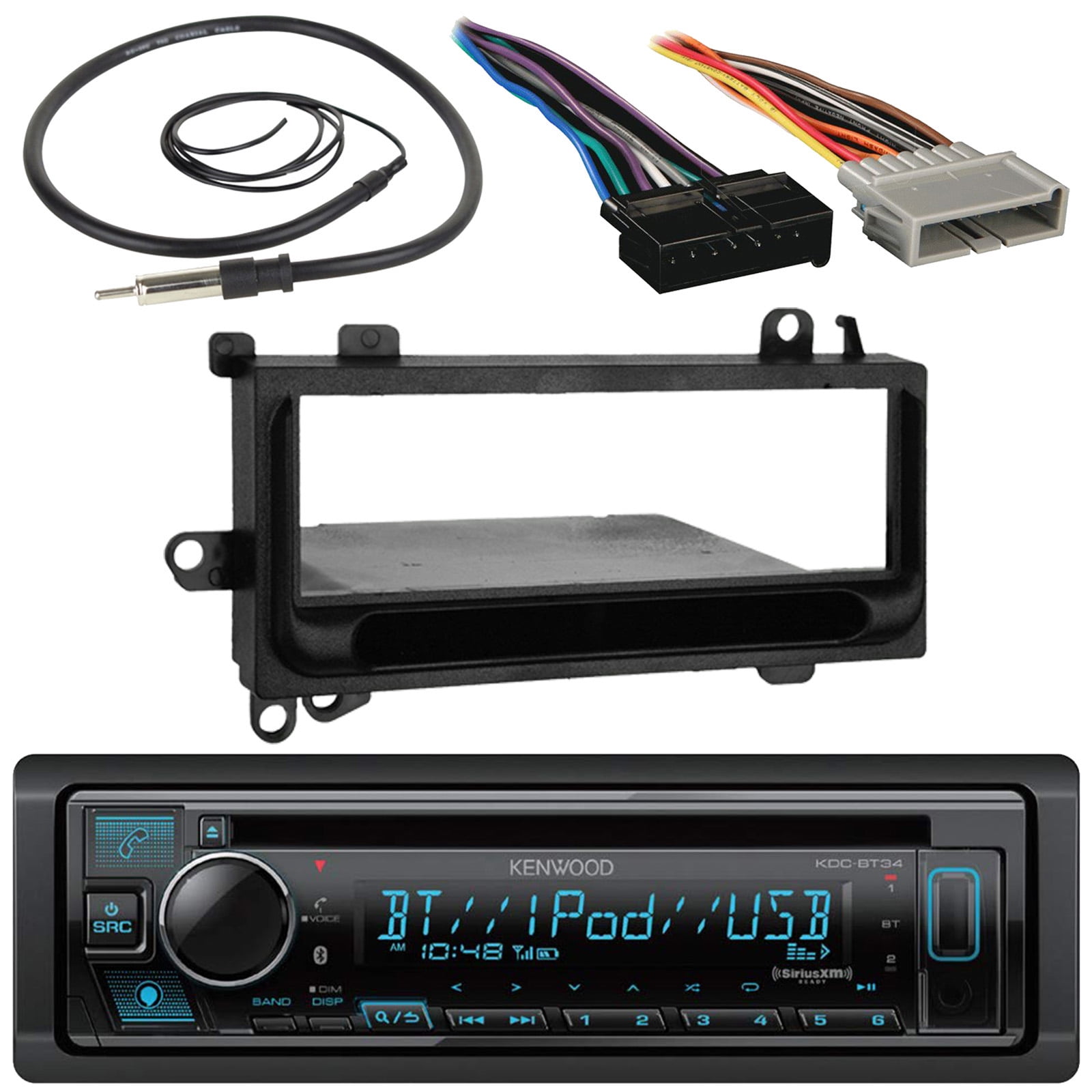
am-fm-6-disc-cd-player-radio-wiring-diagram.pdf
100%

Am Fm 6 Disc Cd Player Radio Wiring Diagram


HTTP://MYDIAGRAM.ONLINE
Revision 2.0 (11/2004)
© 2004 HTTP://MYDIAGRAM.ONLINE. All Rights Reserved.

TABLE OF CONTENTS

Cover1
Table of Contents2
Introduction & Scope3
Safety and Handling4
Symbols & Abbreviations5
Wire Colors & Gauges6
Power Distribution Overview7
Grounding Strategy8
Connector Index & Pinout9
Sensor Inputs10
Actuator Outputs11
Control Unit / Module12
Communication Bus13
Protection: Fuse & Relay14
Test Points & References15
Measurement Procedures16
Troubleshooting Guide17
Common Fault Patterns18
Maintenance & Best Practices19
Appendix & References20
Deep Dive #1 - Signal Integrity & EMC21
Deep Dive #2 - Signal Integrity & EMC22
Deep Dive #3 - Signal Integrity & EMC23
Deep Dive #4 - Signal Integrity & EMC24
Deep Dive #5 - Signal Integrity & EMC25
Deep Dive #6 - Signal Integrity & EMC26
Harness Layout Variant #127
Harness Layout Variant #228
Harness Layout Variant #329
Harness Layout Variant #430
Diagnostic Flowchart #131
Diagnostic Flowchart #232
Diagnostic Flowchart #333
Diagnostic Flowchart #434
Case Study #1 - Real-World Failure35
Case Study #2 - Real-World Failure36
Case Study #3 - Real-World Failure37
Case Study #4 - Real-World Failure38
Case Study #5 - Real-World Failure39
Case Study #6 - Real-World Failure40
Hands-On Lab #1 - Measurement Practice41
Hands-On Lab #2 - Measurement Practice42
Hands-On Lab #3 - Measurement Practice43
Hands-On Lab #4 - Measurement Practice44
Hands-On Lab #5 - Measurement Practice45
Hands-On Lab #6 - Measurement Practice46
Checklist & Form #1 - Quality Verification47
Checklist & Form #2 - Quality Verification48
Checklist & Form #3 - Quality Verification49
Checklist & Form #4 - Quality Verification50
Introduction & Scope Page 3

Traditional wiring is evolving rapidly into intelligent systems. What was once a passive network of copper conductors carrying only electricity and signals has now become an active, data-driven infrastructure. These modern systems can sense their own status, share information, and respond dynamically. The rise of intelligent harnesses and Internet of Things connectivity has reshaped wiring philosophy across industriesfrom vehicles to buildings to factories.

At the core of this evolution lies a shift toward total interconnection. Old wiring could not report its health or performance, built only to transmit electricity from one point to another. Smart systems, however, embed sensors, microcontrollers, and analytics directly within cables and connectors. These devices measure voltage, current, temperature, and vibration and send the data to cloud dashboards or control units. The result is a self-diagnostic network that not only delivers energy but also reports its health, efficiency, and performance.

This capability is especially critical in high-reliability or mission-critical infrastructure. In manufacturing environments, smart harnesses can sense degradation before failure. In modern electric vehicles, IoT-enabled intelligent fuse boxes report faults to control units instantly, isolating issues before they escalate. The fusion of hardware, software, and analytics is what truly makes wiring smart.

### **Key Components of Smart Wiring**

- **Embedded Sensors:** Miniature sensors continuously measure electrical and mechanical conditions. They alert engineers before damage occurs by observing environmental variations and current shifts.
- **Microcontrollers and Edge Processors:** Smart chips interpret readings without cloud delay. This allows instant response to overloads or temperature spikes.
- **Communication Interfaces:** wired and wireless protocols link distributed nodes and gateways for seamless data exchange.
- **Power Electronics Integration:** Solid-state relays, digital fuses, and electronic switches dynamically regulate current flow, replacing mechanical breakers.

Together, these components create a distributed nervous systemone where every wire can sense, think, and communicate.

### **IoT Connectivity and Cloud Integration**

The IoT ecosystem extends wiring intelligence far outside the control cabinet. Through cellular, Wi-Fi, or LAN connections, wiring data flows into cloud platforms. Predictive algorithms then detect patterns and predict failure. Technicians or maintenance teams receive alerts on tablets and cloud consoles, enabling proactive maintenance before faults propagate.

In intelligent infrastructure, IoT-integrated wiring links climate, power, and security subsystems under central control. Sensors automatically adjust energy usage. In agriculture or renewable energy installations, data-driven harnesses transmit environmental and performance metrics.

### **Design Considerations for Smart Wiring**

Embedding intelligence introduces fresh design constraints. Each sensor and microcontroller demands stable voltage and reliable data pathways. Designers must balance signal integrity, flexibility, and shielding. Hybrid cables often combine power and data conductors, saving space while preserving isolation.

Power management is crucial. Smart nodes continuously draw small currents, so systems must include low-power sleep states. Some designs even harvest energy from vibration, heat, or solar exposure.

Cybersecurity becomes part of the electrical design. Secure firmware and access control prevent intrusion into connected harnesses.

### **Applications Across Industries**

- **Automotive:** Modern EV architectures depend on intelligent wiring to manage power and data distribution. Each module reports live performance metrics to onboard diagnostics.
- **Aerospace:** Lightweight, self-aware harnesses reduce maintenance effort under extreme vibration and temperature conditions.
- **Industrial Automation:** Condition-monitoring cables detect wear and insulation breakdown in robots, conveyors, or production lines.
- **Smart Buildings:** IoT-linked wiring coordinates HVAC, lighting, and security systems.
- **Renewable Energy:** Solar farms and wind turbines use smart wiring to detect insulation leakage and load imbalance.

### **Diagnostics and Predictive Maintenance**

The biggest advantage of smart wiring lies in continuous diagnostics. Instead of manual testing, systems now monitor themselves constantly. Machine learning and AI algorithms identify early indicators of degradation such as temperature rise and abnormal waveform distortion.

For instance, an IoT-connected harness can automatically reroute power around a damaged section. Combined with cloud analytics and visualization dashboards, entire facilities can be supervised globally, minimizing cost and preventing unexpected shutdowns.

### **The Future of Wiring Intelligence**

As AI and miniaturization progress, wiring will evolve into adaptive, regenerative systems. Smart polymers and AI-driven current control are already under development. Soon, wiring systems may adjust pathways on demand and optimize energy flow.

Ultimately, smart wiring unites electrical engineering with data science. It turns ordinary wire into a digital organ within a connected ecosystem. For technicians and engineers, mastery now means combining electrical logic with information flow. The future belongs to those who make wires talk.

Figure 1
Safety and Handling Page 4

Preparation defines safe work. Study the wiring diagram to understand circuit paths and identify potential hazards. Tell everyone involved before you shut down or reapply power. Wear eye protection and insulated gloves through inspection and assembly.

Proper handling ensures electrical integrity. Color coding and labeling prevent accidental miswires. Do not cinch cable ties so hard that they slice the jacket over time. Use proper clamps that hold the harness without cutting into it.

After completion, verify all terminals for correct torque. Conduct insulation testing and verify ground continuity. Record all changes in the maintenance notes. Strong safety habits turn complex electrical work into a controlled process.

Figure 2
Symbols & Abbreviations Page 5

A schematic is more than wires; it’s a map of information flow. The symbols tell you which node senses, which node decides, and which node actually drives the load. Whenever you see ECU drawn as a box with arrows, that’s the map of who is sending data in and which outputs it’s commanding out.

The abbreviations next to those arrows tell you what kind of data is moving. TEMP SIG means temperature signal, SPD SIG means speed signal, POS FBK means position feedback, CMD OUT means command output, PWM DRV means pulse‑width‑modulated driver. Those strings tell you if a pin in “Am Fm 6 Disc Cd Player Radio Wiring Diagram” is a passive sensor feed or an active driver.

This matters for probe safety in Wiring Diagram. If a pin is marked SENSOR IN you do not drive it; if it’s DRV OUT you don’t backfeed it because it’s already a driver. Reading those tags first stops you from backfeeding a controller in 2025, protects liability for http://mydiagram.online, and leaves proof in https://http://mydiagram.online/am-fm-6-disc-cd-player-radio-wiring-diagram/ of what was accessed.

Figure 3
Wire Colors & Gauges Page 6

Understanding wire colors and gauges is more than a matter of organization — it’s a matter of safety, reliability, and precision.
Wire color and size give essential clues engineers need to design circuits that meet performance and safety standards.
Red wires usually supply voltage, black or brown act as ground, yellow routes switching or ignition, and blue transmits signal or control data.
When technicians adhere to standard color codes, they can diagnose and service “Am Fm 6 Disc Cd Player Radio Wiring Diagram” efficiently and safely.
Clarity in wiring color is the foundation of every safe and professional electrical installation.

Wire gauge plays an equally important role in electrical system design.
The thickness of a wire dictates how much current it can safely carry before overheating.
A smaller gauge number means a thicker wire capable of carrying more current, while a larger number indicates a thinner conductor with lower capacity.
Across Wiring Diagram, most professionals rely on ISO 6722, SAE J1128, and IEC 60228 standards to determine proper wire sizes.
Using the correct gauge not only prevents component damage but also ensures the system runs efficiently under various load scenarios in “Am Fm 6 Disc Cd Player Radio Wiring Diagram”.
Improper wire sizing causes voltage drops, component wear, or fire in severe overload conditions.

Record-keeping is the last but most vital part of maintaining professional wiring work.
Technicians should log every change in wire color, routing, and gauge within the maintenance record.
When replacement wires are used, color markers or printed labels help maintain consistency and make future inspections easier.
Finished updates must be logged with diagrams and measurements saved under http://mydiagram.online.
Including timestamps (2025) and reference URLs (https://http://mydiagram.online/am-fm-6-disc-cd-player-radio-wiring-diagram/) helps create a transparent record for future diagnostics and audits.
Proper documentation turns complicated wiring into safe, well-organized, and professional systems for “Am Fm 6 Disc Cd Player Radio Wiring Diagram”.

Figure 4
Power Distribution Overview Page 7

Power distribution is the backbone of every electrical system, responsible for transferring energy safely and efficiently across multiple circuits.
It ensures that power from the source is divided properly, preventing overloads and maintaining voltage balance throughout “Am Fm 6 Disc Cd Player Radio Wiring Diagram”.
Without a well-designed power distribution layout, systems can suffer from voltage drops, heat buildup, or even electrical failure.
Proper power network design ensures steady energy, enhances protection, and prolongs component life.
At its core, power distribution ensures modern systems run reliably and efficiently in any environment.

Building an effective power structure requires careful study of load distribution and circuit response.
All wiring and protection elements must meet load, temperature, and operational endurance requirements.
Within Wiring Diagram, these standards define uniform safety and performance criteria for electrical networks.
Power lines should be separated from data and control cables to minimize electromagnetic interference (EMI).
Ground terminals, fuses, and relays should be located conveniently, marked clearly, and kept dry.
By applying these principles, “Am Fm 6 Disc Cd Player Radio Wiring Diagram” maintains stability under environmental and electrical variations.

Testing and reporting form the foundation for ensuring distribution accuracy and system dependability.
Technicians must inspect continuity, measure voltage stability, and verify the effectiveness of grounding.
Any system modifications must be updated in schematic drawings and maintenance databases.
Upload all inspection data and performance reports to http://mydiagram.online for future reference.
Attach 2025 and https://http://mydiagram.online/am-fm-6-disc-cd-player-radio-wiring-diagram/ to maintain transparent, timestamped documentation for maintenance.
Through disciplined design, testing, and documentation, “Am Fm 6 Disc Cd Player Radio Wiring Diagram” maintains consistent performance and long-term electrical safety.

Figure 5
Grounding Strategy Page 8

It offers an electrical baseline that maintains safety, stability, and optimal system function.
It channels excess current into the ground, reducing the risk of electrical shock or failure.
A lack of grounding can cause “Am Fm 6 Disc Cd Player Radio Wiring Diagram” to experience instability, interference, or electrical errors.
A good grounding strategy minimizes these risks by maintaining a low-resistance path and consistent potential balance.
Ultimately, grounding ensures that electrical networks in Wiring Diagram remain safe, stable, and dependable.

A strong grounding plan starts by analyzing soil composition, resistivity, and fault current behavior.
Grounding connections should be secure, rust-proof, and placed for easy maintenance access.
Across Wiring Diagram, engineers follow IEC 60364 and IEEE 142 for consistent grounding quality and safety.
Grounding cables must be properly sized to carry full fault loads without overheating.
All grounding points need to be interconnected to avoid voltage differences and stray current paths.
By implementing these grounding principles, “Am Fm 6 Disc Cd Player Radio Wiring Diagram” achieves reliable, interference-free performance.

Ongoing inspection and testing ensure continued reliability and electrical safety.
Inspectors should test resistance, inspect for loosened bonds, and verify electrical continuity.
If any damage or corrosion is found, immediate repair and retesting are required.
Grounding test logs and maintenance records must be archived for reference and safety audits.
Regular checks every half-year or annually confirm the system’s grounding integrity.
Through consistent testing and upkeep, “Am Fm 6 Disc Cd Player Radio Wiring Diagram” achieves long-term electrical reliability and safe operation.

Figure 6
Connector Index & Pinout Page 9

Am Fm 6 Disc Cd Player Radio Wiring Diagram Full Manual – Connector Index & Pinout Reference 2025

Pin numbering in electrical connectors follows a logical standard to avoid miswiring and ensure accurate troubleshooting. {Numbers are usually assigned from left to right or top to bottom, depending on connector design.|The numbering order typically follows the manufacturer’s specified pattern shown in servi...

A reversed orientation can lead to incorrect readings or short circuits. {Wiring manuals usually include an icon or note that specifies “Connector shown from wire side” or “Terminal side view.”|Manufacturers mark diagrams with clear orientation symbols to prevent this issue.|Service documents always highlight the connector ...

Taking a quick photo before removing connectors helps with reinstallation. {Consistent pin numbering not only improves workflow but also maintains long-term reliability of the harness.|Standardized numbering across all connectors simplifies system documentation and reduces confusion.|Maintaining numbering discipline ensures predictable performance across re...

Figure 7
Sensor Inputs Page 10

Am Fm 6 Disc Cd Player Radio Wiring Diagram Wiring Guide – Sensor Inputs 2025

IAT sensors monitor incoming air temperature to help the ECU calculate air density. {As air temperature changes, the IAT sensor adjusts its resistance, sending a corresponding voltage signal to the ECU.|Colder air increases density and requires more fuel, while warmer air reduces fuel demand.|By reading IAT data, the...

Most IAT sensors are thermistors with negative temperature coefficient (NTC) characteristics. {Some vehicles integrate the IAT sensor within the MAF sensor housing for compact design.|Combined MAF/IAT configurations simplify installation but require specific testing procedures.|Whether standalone or integrated, th...

Technicians should verify voltage signals using temperature reference charts during diagnostics. {Proper maintenance of IAT sensors ensures stable air-fuel control and smooth operation.|Replacing faulty sensors improves responsiveness and reduces engine hesitation.|Understanding IAT input behavior helps o...

Figure 8
Actuator Outputs Page 11

Am Fm 6 Disc Cd Player Radio Wiring Diagram – Actuator Outputs Guide 2025

A relay allows a small control current to switch a larger load safely and efficiently. {When energized, the relay coil generates a magnetic field that pulls a contact arm, closing or opening the circuit.|This mechanism isolates the control side from the load side, protecting sensitive electronics.|The coil’s inductive ...

Electromechanical relays use moving contacts, while solid-state designs rely on semiconductor switching. {Automotive and industrial systems use relays for lamps, fans, motors, and heating elements.|Their ability to handle heavy loads makes them essential in both safety and automation applications.|Each relay type has unique advantages depending o...

A clicking sound usually indicates mechanical operation but not necessarily good contact condition. {Proper relay diagnostics ensure circuit reliability and prevent overload damage.|Regular relay inspection extends service life and maintains stable actuator response.|Understanding relay behavior helps impro...

Figure 9
Control Unit / Module Page 12

Am Fm 6 Disc Cd Player Radio Wiring Diagram Full Manual – Actuator Outputs Reference 2025

Stepper motors are precision actuators that rotate in small, controlled increments. {Each step corresponds to a specific angular displacement determined by motor design.|The ECU or controller sends sequential pulse signals to drive the motor coil phases.|By controlling pulse timing and order, the motor achieves accurate pos...

Bipolar stepper motors provide higher torque and efficiency but require H-bridge control. Their design provides inherent position accuracy without needing encoders.

Microstepping allows smoother motion by dividing steps into smaller increments. Understanding control sequence and polarity ensures proper motor response and reliability.

Figure 10
Communication Bus Page 13

With the increasing adoption of
autonomous‑grade perception modules, the communication bus
simultaneously manages deterministic control loops and high‑throughput
sensor fusion, enabling vehicles to process environmental feedback,
spatial awareness, and actuator response commands in a unified and
synchronized manner.

LIN provides cost‑efficient communication for switch panels,
HVAC actuators, illumination modules, mirror controls, sunroof
mechanisms, interior panels, and other auxiliary circuits that do not
require strict timing constraints but benefit from simplified harness
routing.

Communication bus failures may originate from long‑term impedance
drift, poor shielding continuity, micro‑cracking in conductor strands,
thermal stress accumulation, humidity‑driven oxidation across multi‑pin
connectors, or EMI interference introduced by alternators, ignition
coils, high‑load solenoids, and aftermarket accessories.

Figure 11
Protection: Fuse & Relay Page 14

Fuse‑relay networks
are engineered as frontline safety components that absorb electrical
anomalies long before they compromise essential subsystems. Through
measured response rates and calibrated cutoff thresholds, they ensure
that power surges, short circuits, and intermittent faults remain
contained within predefined zones. This design philosophy prevents
chain‑reaction failures across distributed ECUs.

Automotive fuses vary from micro types to high‑capacity cartridge
formats, each tailored to specific amperage tolerances and activation
speeds. Relays complement them by acting as electronically controlled
switches that manage high‑current operations such as cooling fans, fuel
systems, HVAC blowers, window motors, and ignition‑related loads. The
synergy between rapid fuse interruption and precision relay switching
establishes a controlled electrical environment across all driving
conditions.

Common failures within fuse‑relay assemblies often trace back to
vibration fatigue, corroded terminals, oxidized blades, weak coil
windings, or overheating caused by loose socket contacts. Drivers may
observe symptoms such as flickering accessories, intermittent actuator
response, disabled subsystems, or repeated fuse blows. Proper
diagnostics require voltage‑drop measurements, socket stability checks,
thermal inspection, and coil resistance evaluation.

Figure 12
Test Points & References Page 15

Test points play a foundational role in Am Fm 6 Disc Cd Player Radio Wiring Diagram 2025 Wiring Diagram by
providing waveform analysis routines distributed across the electrical
network. These predefined access nodes allow technicians to capture
stable readings without dismantling complex harness assemblies. By
exposing regulated supply rails, clean ground paths, and buffered signal
channels, test points simplify fault isolation and reduce diagnostic
time when tracking voltage drops, miscommunication between modules, or
irregular load behavior.

Technicians rely on these access nodes to conduct waveform analysis
routines, waveform pattern checks, and signal-shape verification across
multiple operational domains. By comparing known reference values
against observed readings, inconsistencies can quickly reveal poor
grounding, voltage imbalance, or early-stage conductor fatigue. These
cross-checks are essential when diagnosing sporadic faults that only
appear during thermal expansion cycles or variable-load driving
conditions.

Frequent discoveries made at reference nodes
involve irregular waveform signatures, contact oxidation, fluctuating
supply levels, and mechanical fatigue around connector bodies.
Diagnostic procedures include load simulation, voltage-drop mapping, and
ground potential verification to ensure that each subsystem receives
stable and predictable electrical behavior under all operating
conditions.

Figure 13
Measurement Procedures Page 16

Measurement procedures for Am Fm 6 Disc Cd Player Radio Wiring Diagram 2025 Wiring Diagram begin with
ground-offset tracking to establish accurate diagnostic foundations.
Technicians validate stable reference points such as regulator outputs,
ground planes, and sensor baselines before proceeding with deeper
analysis. This ensures reliable interpretation of electrical behavior
under different load and temperature conditions.

Field evaluations often incorporate
chassis-return stability assessment, ensuring comprehensive monitoring
of voltage levels, signal shape, and communication timing. These
measurements reveal hidden failures such as intermittent drops, loose
contacts, or EMI-driven distortions.

Frequent
anomalies identified during procedure-based diagnostics include ground
instability, periodic voltage collapse, digital noise interference, and
contact resistance spikes. Consistent documentation and repeated
sampling are essential to ensure accurate diagnostic conclusions.

Figure 14
Troubleshooting Guide Page 17

Troubleshooting for Am Fm 6 Disc Cd Player Radio Wiring Diagram 2025 Wiring Diagram begins with early-stage
anomaly mapping, ensuring the diagnostic process starts with clarity and
consistency. By checking basic system readiness, technicians avoid
deeper misinterpretations.

Technicians use module drift identification to narrow fault origins. By
validating electrical integrity and observing behavior under controlled
load, they identify abnormal deviations early.

Some faults only reveal themselves under vibration load where wiring
fatigue generates open‑circuit pulses lasting milliseconds, invisible to
basic testers. Oscilloscopes and high‑sampling tools expose these rapid
failures, guiding technicians to fatigue‑prone harness bends.

Figure 15
Common Fault Patterns Page 18

Common fault patterns in Am Fm 6 Disc Cd Player Radio Wiring Diagram 2025 Wiring Diagram frequently stem from
CAN bus frame corruption caused by EMI exposure, a condition that
introduces irregular electrical behavior observable across multiple
subsystems. Early-stage symptoms are often subtle, manifesting as small
deviations in baseline readings or intermittent inconsistencies that
disappear as quickly as they appear. Technicians must therefore begin
diagnostics with broad-spectrum inspection, ensuring that fundamental
supply and return conditions are stable before interpreting more complex
indicators.

Patterns linked to
CAN bus frame corruption caused by EMI exposure frequently reveal
themselves during active subsystem transitions, such as ignition events,
relay switching, or electronic module initialization. The resulting
irregularities—whether sudden voltage dips, digital noise pulses, or
inconsistent ground offset—are best analyzed using waveform-capture
tools that expose micro-level distortions invisible to simple multimeter
checks.

Persistent problems associated with CAN bus frame corruption caused by
EMI exposure can escalate into module desynchronization, sporadic sensor
lockups, or complete loss of communication on shared data lines.
Technicians must examine wiring paths for mechanical fatigue, verify
grounding architecture stability, assess connector tension, and confirm
that supply rails remain steady across temperature changes. Failure to
address these foundational issues often leads to repeated return
visits.

Figure 16
Maintenance & Best Practices Page 19

For
long-term system stability, effective electrical upkeep prioritizes
wire-strand fatigue detection methods, allowing technicians to maintain
predictable performance across voltage-sensitive components. Regular
inspections of wiring runs, connector housings, and grounding anchors
help reveal early indicators of degradation before they escalate into
system-wide inconsistencies.

Addressing concerns tied to wire-strand fatigue detection methods
involves measuring voltage profiles, checking ground offsets, and
evaluating how wiring behaves under thermal load. Technicians also
review terminal retention to ensure secure electrical contact while
preventing micro-arcing events. These steps safeguard signal clarity and
reduce the likelihood of intermittent open circuits.

Issues associated with wire-strand fatigue detection methods frequently
arise from overlooked early wear signs, such as minor contact resistance
increases or softening of insulation under prolonged heat. Regular
maintenance cycles—including resistance indexing, pressure testing, and
moisture-barrier reinforcement—ensure that electrical pathways remain
dependable and free from hidden vulnerabilities.

Figure 17
Appendix & References Page 20

The appendix for Am Fm 6 Disc Cd Player Radio Wiring Diagram 2025 Wiring Diagram serves as a consolidated
reference hub focused on measurement point documentation standards,
offering technicians consistent terminology and structured documentation
practices. By collecting technical descriptors, abbreviations, and
classification rules into a single section, the appendix streamlines
interpretation of wiring layouts across diverse platforms. This ensures
that even complex circuit structures remain approachable through
standardized definitions and reference cues.

Material within the appendix covering measurement
point documentation standards often features quick‑access charts,
terminology groupings, and definition blocks that serve as anchors
during diagnostic work. Technicians rely on these consolidated
references to differentiate between similar connector profiles,
categorize branch circuits, and verify signal classifications.

Comprehensive references for measurement point documentation standards
also support long‑term documentation quality by ensuring uniform
terminology across service manuals, schematics, and diagnostic tools.
When updates occur—whether due to new sensors, revised standards, or
subsystem redesigns—the appendix remains the authoritative source for
maintaining alignment between engineering documentation and real‑world
service practices.

Figure 18
Deep Dive #1 - Signal Integrity & EMC Page 21

Deep analysis of signal integrity in Am Fm 6 Disc Cd Player Radio Wiring Diagram 2025 Wiring Diagram requires
investigating how ground-loop conflicts across distributed modules
disrupts expected waveform performance across interconnected circuits.
As signals propagate through long harnesses, subtle distortions
accumulate due to impedance shifts, parasitic capacitance, and external
electromagnetic stress. This foundational assessment enables technicians
to understand where integrity loss begins and how it
evolves.

When ground-loop conflicts across distributed modules occurs, signals
may experience phase delays, amplitude decay, or transient ringing
depending on harness composition and environmental exposure. Technicians
must review waveform transitions under varying thermal, load, and EMI
conditions. Tools such as high‑bandwidth oscilloscopes and frequency
analyzers reveal distortion patterns that remain hidden during static
measurements.

If ground-loop
conflicts across distributed modules persists, cascading instability may
arise: intermittent communication, corrupt data frames, or erratic
control logic. Mitigation requires strengthening shielding layers,
rebalancing grounding networks, refining harness layout, and applying
proper termination strategies. These corrective steps restore signal
coherence under EMC stress.

Figure 19
Deep Dive #2 - Signal Integrity & EMC Page 22

Advanced EMC evaluation in Am Fm 6 Disc Cd Player Radio Wiring Diagram 2025 Wiring Diagram requires close
study of conducted emissions penetrating low‑voltage control circuits, a
phenomenon that can significantly compromise waveform predictability. As
systems scale toward higher bandwidth and greater sensitivity, minor
deviations in signal symmetry or reference alignment become amplified.
Understanding the initial conditions that trigger these distortions
allows technicians to anticipate system vulnerabilities before they
escalate.

When conducted emissions penetrating low‑voltage control circuits is
present, it may introduce waveform skew, in-band noise, or pulse
deformation that impacts the accuracy of both analog and digital
subsystems. Technicians must examine behavior under load, evaluate the
impact of switching events, and compare multi-frequency responses.
High‑resolution oscilloscopes and field probes reveal distortion
patterns hidden in time-domain measurements.

If left unresolved, conducted emissions
penetrating low‑voltage control circuits may trigger cascading
disruptions including frame corruption, false sensor readings, and
irregular module coordination. Effective countermeasures include
controlled grounding, noise‑filter deployment, re‑termination of
critical paths, and restructuring of cable routing to minimize
electromagnetic coupling.

Figure 20
Deep Dive #3 - Signal Integrity & EMC Page 23

Deep diagnostic exploration of signal integrity in Am Fm 6 Disc Cd Player Radio Wiring Diagram 2025
Wiring Diagram must consider how capacitive absorption along tightly bundled
mixed-signal cables alters the electrical behavior of communication
pathways. As signal frequencies increase or environmental
electromagnetic conditions intensify, waveform precision becomes
sensitive to even minor impedance gradients. Technicians therefore begin
evaluation by mapping signal propagation under controlled conditions and
identifying baseline distortion characteristics.

Systems experiencing capacitive absorption along tightly
bundled mixed-signal cables often show dynamic fluctuations during
transitions such as relay switching, injector activation, or alternator
charging ramps. These transitions inject complex disturbances into
shared wiring paths, making it essential to perform frequency-domain
inspection, spectral decomposition, and transient-load waveform sampling
to fully characterize the EMC interaction.

If
unchecked, capacitive absorption along tightly bundled mixed-signal
cables can escalate into broader electrical instability, causing
corruption of data frames, synchronization loss between modules, and
unpredictable actuator behavior. Effective corrective action requires
ground isolation improvements, controlled harness rerouting, adaptive
termination practices, and installation of noise-suppression elements
tailored to the affected frequency range.

Figure 21
Deep Dive #4 - Signal Integrity & EMC Page 24

Evaluating advanced signal‑integrity interactions involves
examining the influence of dynamic reference collapse triggered by
simultaneous module sync, a phenomenon capable of inducing significant
waveform displacement. These disruptions often develop gradually,
becoming noticeable only when communication reliability begins to drift
or subsystem timing loses coherence.

Systems experiencing
dynamic reference collapse triggered by simultaneous module sync
frequently show instability during high‑demand operational windows, such
as engine load surges, rapid relay switching, or simultaneous
communication bursts. These events amplify embedded EMI vectors, making
spectral analysis essential for identifying the root interference mode.

Long‑term exposure to dynamic reference collapse triggered by
simultaneous module sync can create cascading waveform degradation,
arbitration failures, module desynchronization, or persistent sensor
inconsistency. Corrective strategies include impedance tuning, shielding
reinforcement, ground‑path rebalancing, and reconfiguration of sensitive
routing segments. These adjustments restore predictable system behavior
under varied EMI conditions.

Figure 22
Deep Dive #5 - Signal Integrity & EMC Page 25

In-depth
signal integrity analysis requires understanding how harmonic stacking
during injector modulation cycles influences propagation across
mixed-frequency network paths. These distortions may remain hidden
during low-load conditions, only becoming evident when multiple modules
operate simultaneously or when thermal boundaries shift.

Systems exposed to harmonic stacking during injector
modulation cycles often show instability during rapid subsystem
transitions. This instability results from interference coupling into
sensitive wiring paths, causing skew, jitter, or frame corruption.
Multi-domain waveform capture reveals how these disturbances propagate
and interact.

If left
unresolved, harmonic stacking during injector modulation cycles may
evolve into severe operational instability—ranging from data corruption
to sporadic ECU desynchronization. Effective countermeasures include
refining harness geometry, isolating radiated hotspots, enhancing
return-path uniformity, and implementing frequency-specific suppression
techniques.

Figure 23
Deep Dive #6 - Signal Integrity & EMC Page 26

Advanced EMC analysis in Am Fm 6 Disc Cd Player Radio Wiring Diagram 2025 Wiring Diagram must consider
catastrophic module desynchronization caused by transient reference
collapse, a complex interaction capable of reshaping waveform integrity
across numerous interconnected subsystems. As modern vehicles integrate
high-speed communication layers, ADAS modules, EV power electronics, and
dense mixed-signal harness routing, even subtle non-linear effects can
disrupt deterministic timing and system reliability.

When catastrophic module desynchronization caused by transient
reference collapse occurs, technicians may observe inconsistent
rise-times, amplitude drift, complex ringing patterns, or intermittent
jitter artifacts. These symptoms often appear during subsystem
interactions—such as inverter ramps, actuator bursts, ADAS
synchronization cycles, or ground-potential fluctuations. High-bandwidth
oscilloscopes and spectrum analyzers reveal hidden distortion
signatures.

If unresolved,
catastrophic module desynchronization caused by transient reference
collapse can escalate into catastrophic failure modes—ranging from
module resets and actuator misfires to complete subsystem
desynchronization. Effective corrective actions include tuning impedance
profiles, isolating radiated hotspots, applying frequency-specific
suppression, and refining communication topology to ensure long-term
stability.

Figure 24
Harness Layout Variant #1 Page 27

In-depth planning of
harness architecture involves understanding how anchoring‑point symmetry
to maintain harness tension balance affects long-term stability. As
wiring systems grow more complex, engineers must consider structural
constraints, subsystem interaction, and the balance between electrical
separation and mechanical compactness.

During layout development, anchoring‑point symmetry to maintain harness
tension balance can determine whether circuits maintain clean signal
behavior under dynamic operating conditions. Mechanical and electrical
domains intersect heavily in modern harness designs—routing angle,
bundling tightness, grounding alignment, and mounting intervals all
affect susceptibility to noise, wear, and heat.

Proper control of anchoring‑point symmetry to maintain harness tension
balance ensures reliable operation, simplified manufacturing, and
long-term durability. Technicians and engineers apply routing
guidelines, shielding rules, and structural anchoring principles to
ensure consistent performance regardless of environment or subsystem
load.

Figure 25
Harness Layout Variant #2 Page 28

The engineering process behind
Harness Layout Variant #2 evaluates how drain-wire orientation improving
shielding effectiveness interacts with subsystem density, mounting
geometry, EMI exposure, and serviceability. This foundational planning
ensures clean routing paths and consistent system behavior over the
vehicle’s full operating life.

During refinement, drain-wire orientation improving shielding
effectiveness impacts EMI susceptibility, heat distribution, vibration
loading, and ground continuity. Designers analyze spacing, elevation
changes, shielding alignment, tie-point positioning, and path curvature
to ensure the harness resists mechanical fatigue while maintaining
electrical integrity.

If neglected,
drain-wire orientation improving shielding effectiveness may cause
abrasion, insulation damage, intermittent electrical noise, or alignment
stress on connectors. Precision anchoring, balanced tensioning, and
correct separation distances significantly reduce such failure risks
across the vehicle’s entire electrical architecture.

Figure 26
Harness Layout Variant #3 Page 29

Engineering Harness Layout
Variant #3 involves assessing how precision grommet staging across
multi-layer firewall structures influences subsystem spacing, EMI
exposure, mounting geometry, and overall routing efficiency. As harness
density increases, thoughtful initial planning becomes critical to
prevent premature system fatigue.

In real-world
operation, precision grommet staging across multi-layer firewall
structures determines how the harness responds to thermal cycling,
chassis motion, subsystem vibration, and environmental elements. Proper
connector staging, strategic bundling, and controlled curvature help
maintain stable performance even in aggressive duty cycles.

If not
addressed, precision grommet staging across multi-layer firewall
structures may lead to premature insulation wear, abrasion hotspots,
intermittent electrical noise, or connector fatigue. Balanced
tensioning, routing symmetry, and strategic material selection
significantly mitigate these risks across all major vehicle subsystems.

Figure 27
Harness Layout Variant #4 Page 30

The
architectural approach for this variant prioritizes service-first harness zoning for quick module replacement,
focusing on service access, electrical noise reduction, and long-term durability. Engineers balance bundle
compactness with proper signal separation to avoid EMI coupling while keeping the routing footprint
efficient.

In
real-world operation, service-first harness zoning for quick module replacement affects signal quality near
actuators, motors, and infotainment modules. Cable elevation, branch sequencing, and anti-chafe barriers
reduce premature wear. A combination of elastic tie-points, protective sleeves, and low-profile clips keeps
bundles orderly yet flexible under dynamic loads.

If overlooked, service-first harness zoning for quick module replacement may lead to insulation
wear, loose connections, or intermittent signal faults caused by chafing. Solutions include anchor
repositioning, spacing corrections, added shielding, and branch restructuring to shorten paths and improve
long-term serviceability.

Figure 28
Diagnostic Flowchart #1 Page 31

The initial stage of
Diagnostic Flowchart #1 emphasizes progressive resistance mapping for suspected corrosion paths, ensuring that
the most foundational electrical references are validated before branching into deeper subsystem evaluation.
This reduces misdirection caused by surface‑level symptoms. Mid‑stage analysis integrates progressive
resistance mapping for suspected corrosion paths into a structured decision tree, allowing each measurement to
eliminate specific classes of faults. By progressively narrowing the fault domain, the technician accelerates
isolation of underlying issues such as inconsistent module timing, weak grounds, or intermittent sensor
behavior. If progressive resistance mapping for suspected corrosion paths is
not thoroughly validated, subtle faults can cascade into widespread subsystem instability. Reinforcing each
decision node with targeted measurements improves long‑term reliability and prevents misdiagnosis.

Figure 29
Diagnostic Flowchart #2 Page 32

Diagnostic Flowchart #2 for Am Fm 6 Disc Cd Player Radio Wiring Diagram 2025 Wiring Diagram begins by addressing stepwise verification of relay-
driven circuit transitions, establishing a clear entry point for isolating electrical irregularities that may
appear intermittent or load‑dependent. Technicians rely on this structured starting node to avoid
misinterpretation of symptoms caused by secondary effects. As the diagnostic flow advances, stepwise
verification of relay-driven circuit transitions shapes the logic of each decision node. Mid‑stage evaluation
involves segmenting power, ground, communication, and actuation pathways to progressively narrow down fault
origins. This stepwise refinement is crucial for revealing timing‑related and load‑sensitive
anomalies. If
stepwise verification of relay-driven circuit transitions is not thoroughly examined, intermittent signal
distortion or cascading electrical faults may remain hidden. Reinforcing each decision node with precise
measurement steps prevents misdiagnosis and strengthens long-term reliability.

Figure 30
Diagnostic Flowchart #3 Page 33

Diagnostic Flowchart #3 for Am Fm 6 Disc Cd Player Radio Wiring Diagram 2025 Wiring Diagram initiates with multi‑ECU arbitration desync during
high‑traffic CAN cycles, establishing a strategic entry point for technicians to separate primary electrical
faults from secondary symptoms. By evaluating the system from a structured baseline, the diagnostic process
becomes far more efficient. Throughout
the analysis, multi‑ECU arbitration desync during high‑traffic CAN cycles interacts with branching decision
logic tied to grounding stability, module synchronization, and sensor referencing. Each step narrows the
diagnostic window, improving root‑cause accuracy. Once multi‑ECU arbitration desync during high‑traffic CAN
cycles is fully evaluated across multiple load states, the technician can confirm or dismiss entire fault
categories. This structured approach enhances long‑term reliability and reduces repeat troubleshooting
visits.

Figure 31
Diagnostic Flowchart #4 Page 34

Diagnostic Flowchart #4 for Am Fm 6 Disc Cd Player Radio Wiring Diagram 2025
Wiring Diagram focuses on progressive isolation of gateway routing anomalies, laying the foundation for a structured
fault‑isolation path that eliminates guesswork and reduces unnecessary component swapping. The first stage
examines core references, voltage stability, and baseline communication health to determine whether the issue
originates in the primary network layer or in a secondary subsystem. Technicians follow a branched decision
flow that evaluates signal symmetry, grounding patterns, and frame stability before advancing into deeper
diagnostic layers. As the evaluation continues, progressive isolation of gateway routing anomalies becomes the
controlling factor for mid‑level branch decisions. This includes correlating waveform alignment, identifying
momentary desync signatures, and interpreting module wake‑timing conflicts. By dividing the diagnostic pathway
into focused electrical domains—power delivery, grounding integrity, communication architecture, and actuator
response—the flowchart ensures that each stage removes entire categories of faults with minimal overlap. This
structured segmentation accelerates troubleshooting and increases diagnostic precision. The final stage ensures that progressive isolation of
gateway routing anomalies is validated under multiple operating conditions, including thermal stress, load
spikes, vibration, and state transitions. These controlled stress points help reveal hidden instabilities that
may not appear during static testing. Completing all verification nodes ensures long‑term stability, reducing
the likelihood of recurring issues and enabling technicians to document clear, repeatable steps for future
diagnostics.

Figure 32
Case Study #1 - Real-World Failure Page 35

Case Study #1 for Am Fm 6 Disc Cd Player Radio Wiring Diagram 2025 Wiring Diagram examines a real‑world failure involving sensor drift originating
from a heat‑soaked MAP sensor nearing end‑of‑life. The issue first appeared as an intermittent symptom that
did not trigger a consistent fault code, causing technicians to suspect unrelated components. Early
observations highlighted irregular electrical behavior, such as momentary signal distortion, delayed module
responses, or fluctuating reference values. These symptoms tended to surface under specific thermal,
vibration, or load conditions, making replication difficult during static diagnostic tests. Further
investigation into sensor drift originating from a heat‑soaked MAP sensor nearing end‑of‑life required
systematic measurement across power distribution paths, grounding nodes, and communication channels.
Technicians used targeted diagnostic flowcharts to isolate variables such as voltage drop, EMI exposure,
timing skew, and subsystem desynchronization. By reproducing the fault under controlled conditions—applying
heat, inducing vibration, or simulating high load—they identified the precise moment the failure manifested.
This structured process eliminated multiple potential contributors, narrowing the fault domain to a specific
harness segment, component group, or module logic pathway. The confirmed cause tied to sensor drift
originating from a heat‑soaked MAP sensor nearing end‑of‑life allowed technicians to implement the correct
repair, whether through component replacement, harness restoration, recalibration, or module reprogramming.
After corrective action, the system was subjected to repeated verification cycles to ensure long‑term
stability under all operating conditions. Documenting the failure pattern and diagnostic sequence provided
valuable reference material for similar future cases, reducing diagnostic time and preventing unnecessary part
replacement.

Figure 33
Case Study #2 - Real-World Failure Page 36

Case Study #2 for Am Fm 6 Disc Cd Player Radio Wiring Diagram 2025 Wiring Diagram examines a real‑world failure involving mixed‑voltage coupling
inside a fatigued firewall pass‑through. The issue presented itself with intermittent symptoms that varied
depending on temperature, load, or vehicle motion. Technicians initially observed irregular system responses,
inconsistent sensor readings, or sporadic communication drops. Because the symptoms did not follow a
predictable pattern, early attempts at replication were unsuccessful, leading to misleading assumptions about
unrelated subsystems. A detailed investigation into mixed‑voltage coupling inside a fatigued firewall
pass‑through required structured diagnostic branching that isolated power delivery, ground stability,
communication timing, and sensor integrity. Using controlled diagnostic tools, technicians applied thermal
load, vibration, and staged electrical demand to recreate the failure in a measurable environment. Progressive
elimination of subsystem groups—ECUs, harness segments, reference points, and actuator pathways—helped reveal
how the failure manifested only under specific operating thresholds. This systematic breakdown prevented
misdiagnosis and reduced unnecessary component swaps. Once the cause linked to mixed‑voltage coupling inside
a fatigued firewall pass‑through was confirmed, the corrective action involved either reconditioning the
harness, replacing the affected component, reprogramming module firmware, or adjusting calibration parameters.
Post‑repair validation cycles were performed under varied conditions to ensure long‑term reliability and
prevent future recurrence. Documentation of the failure characteristics, diagnostic sequence, and final
resolution now serves as a reference for addressing similar complex faults more efficiently.

Figure 34
Case Study #3 - Real-World Failure Page 37

Case Study #3 for Am Fm 6 Disc Cd Player Radio Wiring Diagram 2025 Wiring Diagram focuses on a real‑world failure involving frame‑retry escalation on
Ethernet‑based modules under RF interference. Technicians first observed erratic system behavior, including
fluctuating sensor values, delayed control responses, and sporadic communication warnings. These symptoms
appeared inconsistently, often only under specific temperature, load, or vibration conditions. Early
troubleshooting attempts failed to replicate the issue reliably, creating the impression of multiple unrelated
subsystem faults rather than a single root cause. To investigate frame‑retry escalation on Ethernet‑based
modules under RF interference, a structured diagnostic approach was essential. Technicians conducted staged
power and ground validation, followed by controlled stress testing that included thermal loading, vibration
simulation, and alternating electrical demand. This method helped reveal the precise operational threshold at
which the failure manifested. By isolating system domains—communication networks, power rails, grounding
nodes, and actuator pathways—the diagnostic team progressively eliminated misleading symptoms and narrowed the
problem to a specific failure mechanism. After identifying the underlying cause tied to frame‑retry
escalation on Ethernet‑based modules under RF interference, technicians carried out targeted corrective
actions such as replacing compromised components, restoring harness integrity, updating ECU firmware, or
recalibrating affected subsystems. Post‑repair validation cycles confirmed stable performance across all
operating conditions. The documented diagnostic path and resolution now serve as a repeatable reference for
addressing similar failures with greater speed and accuracy.

Figure 35
Case Study #4 - Real-World Failure Page 38

Case Study #4 for Am Fm 6 Disc Cd Player Radio Wiring Diagram 2025 Wiring Diagram examines a high‑complexity real‑world failure involving sensor
resolution collapse during high‑frequency vibration exposure. The issue manifested across multiple subsystems
simultaneously, creating an array of misleading symptoms ranging from inconsistent module responses to
distorted sensor feedback and intermittent communication warnings. Initial diagnostics were inconclusive due
to the fault’s dependency on vibration, thermal shifts, or rapid load changes. These fluctuating conditions
allowed the failure to remain dormant during static testing, pushing technicians to explore deeper system
interactions that extended beyond conventional troubleshooting frameworks. To investigate sensor resolution
collapse during high‑frequency vibration exposure, technicians implemented a layered diagnostic workflow
combining power‑rail monitoring, ground‑path validation, EMI tracing, and logic‑layer analysis. Stress tests
were applied in controlled sequences to recreate the precise environment in which the instability
surfaced—often requiring synchronized heat, vibration, and electrical load modulation. By isolating
communication domains, verifying timing thresholds, and comparing analog sensor behavior under dynamic
conditions, the diagnostic team uncovered subtle inconsistencies that pointed toward deeper system‑level
interactions rather than isolated component faults. After confirming the root mechanism tied to sensor
resolution collapse during high‑frequency vibration exposure, corrective action involved component
replacement, harness reconditioning, ground‑plane reinforcement, or ECU firmware restructuring depending on
the failure’s nature. Technicians performed post‑repair endurance tests that included repeated thermal
cycling, vibration exposure, and electrical stress to guarantee long‑term system stability. Thorough
documentation of the analysis method, failure pattern, and final resolution now serves as a highly valuable
reference for identifying and mitigating similar high‑complexity failures in the future.

Figure 36
Case Study #5 - Real-World Failure Page 39

Case Study #5 for Am Fm 6 Disc Cd Player Radio Wiring Diagram 2025 Wiring Diagram investigates a complex real‑world failure involving frame‑loss
bursts across Ethernet‑based diagnostic modules. The issue initially presented as an inconsistent mixture of
delayed system reactions, irregular sensor values, and sporadic communication disruptions. These events tended
to appear under dynamic operational conditions—such as elevated temperatures, sudden load transitions, or
mechanical vibration—which made early replication attempts unreliable. Technicians encountered symptoms
occurring across multiple modules simultaneously, suggesting a deeper systemic interaction rather than a
single isolated component failure. During the investigation of frame‑loss bursts across Ethernet‑based
diagnostic modules, a multi‑layered diagnostic workflow was deployed. Technicians performed sequential
power‑rail mapping, ground‑plane verification, and high‑frequency noise tracing to detect hidden
instabilities. Controlled stress testing—including targeted heat application, induced vibration, and variable
load modulation—was carried out to reproduce the failure consistently. The team methodically isolated
subsystem domains such as communication networks, analog sensor paths, actuator control logic, and module
synchronization timing. This progressive elimination approach identified critical operational thresholds where
the failure reliably emerged. After determining the underlying mechanism tied to frame‑loss bursts across
Ethernet‑based diagnostic modules, technicians carried out corrective actions that ranged from harness
reconditioning and connector reinforcement to firmware restructuring and recalibration of affected modules.
Post‑repair validation involved repeated cycles of vibration, thermal stress, and voltage fluctuation to
ensure long‑term stability and eliminate the possibility of recurrence. The documented resolution pathway now
serves as an advanced reference model for diagnosing similarly complex failures across modern vehicle
platforms.

Figure 37
Case Study #6 - Real-World Failure Page 40

Case Study #6 for Am Fm 6 Disc Cd Player Radio Wiring Diagram 2025 Wiring Diagram examines a complex real‑world failure involving cooling‑module
logic freeze triggered by micro‑arcing on supply lines. Symptoms emerged irregularly, with clustered faults
appearing across unrelated modules, giving the impression of multiple simultaneous subsystem failures. These
irregularities depended strongly on vibration, temperature shifts, or abrupt electrical load changes, making
the issue difficult to reproduce during initial diagnostic attempts. Technicians noted inconsistent sensor
feedback, communication delays, and momentary power‑rail fluctuations that persisted without generating
definitive fault codes. The investigation into cooling‑module logic freeze triggered by micro‑arcing on
supply lines required a multi‑layer diagnostic strategy combining signal‑path tracing, ground stability
assessment, and high‑frequency noise evaluation. Technicians executed controlled stress tests—including
thermal cycling, vibration induction, and staged electrical loading—to reveal the exact thresholds at which
the fault manifested. Using structured elimination across harness segments, module clusters, and reference
nodes, they isolated subtle timing deviations, analog distortions, or communication desynchronization that
pointed toward a deeper systemic failure mechanism rather than isolated component malfunction. Once
cooling‑module logic freeze triggered by micro‑arcing on supply lines was identified as the root failure
mechanism, targeted corrective measures were implemented. These included harness reinforcement, connector
replacement, firmware restructuring, recalibration of key modules, or ground‑path reconfiguration depending on
the nature of the instability. Post‑repair endurance runs with repeated vibration, heat cycles, and voltage
stress ensured long‑term reliability. Documentation of the diagnostic sequence and recovery pathway now
provides a vital reference for detecting and resolving similarly complex failures more efficiently in future
service operations.

Figure 38
Hands-On Lab #1 - Measurement Practice Page 41

Hands‑On Lab #1 for Am Fm 6 Disc Cd Player Radio Wiring Diagram 2025 Wiring Diagram focuses on HV/LV isolation verification using differential
probing. This exercise teaches technicians how to perform structured diagnostic measurements using
multimeters, oscilloscopes, current probes, and differential tools. The initial phase emphasizes establishing
a stable baseline by checking reference voltages, verifying continuity, and confirming ground integrity. These
foundational steps ensure that subsequent measurements reflect true system behavior rather than secondary
anomalies introduced by poor probing technique or unstable electrical conditions. During the measurement
routine for HV/LV isolation verification using differential probing, technicians analyze dynamic behavior by
applying controlled load, capturing waveform transitions, and monitoring subsystem responses. This includes
observing timing shifts, duty‑cycle changes, ripple patterns, or communication irregularities. By replicating
real operating conditions—thermal changes, vibration, or electrical demand spikes—technicians gain insight
into how the system behaves under stress. This approach allows deeper interpretation of patterns that static
readings cannot reveal. After completing the procedure for HV/LV isolation verification using differential
probing, results are documented with precise measurement values, waveform captures, and interpretation notes.
Technicians compare the observed data with known good references to determine whether performance falls within
acceptable thresholds. The collected information not only confirms system health but also builds long‑term
diagnostic proficiency by helping technicians recognize early indicators of failure and understand how small
variations can evolve into larger issues.

Figure 39
Hands-On Lab #2 - Measurement Practice Page 42

Hands‑On Lab #2 for Am Fm 6 Disc Cd Player Radio Wiring Diagram 2025 Wiring Diagram focuses on relay activation delay characterization under variable
loads. This practical exercise expands technician measurement skills by emphasizing accurate probing
technique, stable reference validation, and controlled test‑environment setup. Establishing baseline
readings—such as reference ground, regulated voltage output, and static waveform characteristics—is essential
before any dynamic testing occurs. These foundational checks prevent misinterpretation caused by poor tool
placement, floating grounds, or unstable measurement conditions. During the procedure for relay activation
delay characterization under variable loads, technicians simulate operating conditions using thermal stress,
vibration input, and staged subsystem loading. Dynamic measurements reveal timing inconsistencies, amplitude
drift, duty‑cycle changes, communication irregularities, or nonlinear sensor behavior. Oscilloscopes, current
probes, and differential meters are used to capture high‑resolution waveform data, enabling technicians to
identify subtle deviations that static multimeter readings cannot detect. Emphasis is placed on interpreting
waveform shape, slope, ripple components, and synchronization accuracy across interacting modules. After
completing the measurement routine for relay activation delay characterization under variable loads,
technicians document quantitative findings—including waveform captures, voltage ranges, timing intervals, and
noise signatures. The recorded results are compared to known‑good references to determine subsystem health and
detect early‑stage degradation. This structured approach not only builds diagnostic proficiency but also
enhances a technician’s ability to predict emerging faults before they manifest as critical failures,
strengthening long‑term reliability of the entire system.

Figure 40
Hands-On Lab #3 - Measurement Practice Page 43

Hands‑On Lab #3 for Am Fm 6 Disc Cd Player Radio Wiring Diagram 2025 Wiring Diagram focuses on high‑load voltage stability analysis during subsystem
ramp-up. This exercise trains technicians to establish accurate baseline measurements before introducing
dynamic stress. Initial steps include validating reference grounds, confirming supply‑rail stability, and
ensuring probing accuracy. These fundamentals prevent distorted readings and help ensure that waveform
captures or voltage measurements reflect true electrical behavior rather than artifacts caused by improper
setup or tool noise. During the diagnostic routine for high‑load voltage stability analysis during subsystem
ramp-up, technicians apply controlled environmental adjustments such as thermal cycling, vibration, electrical
loading, and communication traffic modulation. These dynamic inputs help expose timing drift, ripple growth,
duty‑cycle deviations, analog‑signal distortion, or module synchronization errors. Oscilloscopes, clamp
meters, and differential probes are used extensively to capture transitional data that cannot be observed with
static measurements alone. After completing the measurement sequence for high‑load voltage stability analysis
during subsystem ramp-up, technicians document waveform characteristics, voltage ranges, current behavior,
communication timing variations, and noise patterns. Comparison with known‑good datasets allows early
detection of performance anomalies and marginal conditions. This structured measurement methodology
strengthens diagnostic confidence and enables technicians to identify subtle degradation before it becomes a
critical operational failure.

Figure 41
Hands-On Lab #4 - Measurement Practice Page 44

Hands‑On Lab #4 for Am Fm 6 Disc Cd Player Radio Wiring Diagram 2025 Wiring Diagram focuses on module wake‑signal propagation delay evaluation. This
laboratory exercise builds on prior modules by emphasizing deeper measurement accuracy, environment control,
and test‑condition replication. Technicians begin by validating stable reference grounds, confirming regulated
supply integrity, and preparing measurement tools such as oscilloscopes, current probes, and high‑bandwidth
differential probes. Establishing clean baselines ensures that subsequent waveform analysis is meaningful and
not influenced by tool noise or ground drift. During the measurement procedure for module wake‑signal
propagation delay evaluation, technicians introduce dynamic variations including staged electrical loading,
thermal cycling, vibration input, or communication‑bus saturation. These conditions reveal real‑time behaviors
such as timing drift, amplitude instability, duty‑cycle deviation, ripple formation, or synchronization loss
between interacting modules. High‑resolution waveform capture enables technicians to observe subtle waveform
features—slew rate, edge deformation, overshoot, undershoot, noise bursts, and harmonic artifacts. Upon
completing the assessment for module wake‑signal propagation delay evaluation, all findings are documented
with waveform snapshots, quantitative measurements, and diagnostic interpretations. Comparing collected data
with verified reference signatures helps identify early‑stage degradation, marginal component performance, and
hidden instability trends. This rigorous measurement framework strengthens diagnostic precision and ensures
that technicians can detect complex electrical issues long before they evolve into system‑wide failures.

Figure 42
Hands-On Lab #5 - Measurement Practice Page 45

Hands‑On Lab #5 for Am Fm 6 Disc Cd Player Radio Wiring Diagram 2025 Wiring Diagram focuses on ABS tone‑ring signal deviation measurement under
variable wheel speed. The session begins with establishing stable measurement baselines by validating
grounding integrity, confirming supply‑rail stability, and ensuring probe calibration. These steps prevent
erroneous readings and ensure that all waveform captures accurately reflect subsystem behavior. High‑accuracy
tools such as oscilloscopes, clamp meters, and differential probes are prepared to avoid ground‑loop artifacts
or measurement noise. During the procedure for ABS tone‑ring signal deviation measurement under variable
wheel speed, technicians introduce dynamic test conditions such as controlled load spikes, thermal cycling,
vibration, and communication saturation. These deliberate stresses expose real‑time effects like timing
jitter, duty‑cycle deformation, signal‑edge distortion, ripple growth, and cross‑module synchronization drift.
High‑resolution waveform captures allow technicians to identify anomalies that static tests cannot reveal,
such as harmonic noise, high‑frequency interference, or momentary dropouts in communication signals. After
completing all measurements for ABS tone‑ring signal deviation measurement under variable wheel speed,
technicians document voltage ranges, timing intervals, waveform shapes, noise signatures, and current‑draw
curves. These results are compared against known‑good references to identify early‑stage degradation or
marginal component behavior. Through this structured measurement framework, technicians strengthen diagnostic
accuracy and develop long‑term proficiency in detecting subtle trends that could lead to future system
failures.

Figure 43
Hands-On Lab #6 - Measurement Practice Page 46

Hands‑On Lab #6 for Am Fm 6 Disc Cd Player Radio Wiring Diagram 2025 Wiring Diagram focuses on ECU power‑rail ripple signature profiling via FFT
inspection. This advanced laboratory module strengthens technician capability in capturing high‑accuracy
diagnostic measurements. The session begins with baseline validation of ground reference integrity, regulated
supply behavior, and probe calibration. Ensuring noise‑free, stable baselines prevents waveform distortion and
guarantees that all readings reflect genuine subsystem behavior rather than tool‑induced artifacts or
grounding errors. Technicians then apply controlled environmental modulation such as thermal shocks,
vibration exposure, staged load cycling, and communication traffic saturation. These dynamic conditions reveal
subtle faults including timing jitter, duty‑cycle deformation, amplitude fluctuation, edge‑rate distortion,
harmonic buildup, ripple amplification, and module synchronization drift. High‑bandwidth oscilloscopes,
differential probes, and current clamps are used to capture transient behaviors invisible to static multimeter
measurements. Following completion of the measurement routine for ECU power‑rail ripple signature profiling
via FFT inspection, technicians document waveform shapes, voltage windows, timing offsets, noise signatures,
and current patterns. Results are compared against validated reference datasets to detect early‑stage
degradation or marginal component behavior. By mastering this structured diagnostic framework, technicians
build long‑term proficiency and can identify complex electrical instabilities before they lead to full system
failure.

Figure 44
Checklist & Form #1 - Quality Verification Page 47

Checklist & Form #1 for Am Fm 6 Disc Cd Player Radio Wiring Diagram 2025 Wiring Diagram focuses on network‑latency and arbitration‑timing
verification sheet. This verification document provides a structured method for ensuring electrical and
electronic subsystems meet required performance standards. Technicians begin by confirming baseline conditions
such as stable reference grounds, regulated voltage supplies, and proper connector engagement. Establishing
these baselines prevents false readings and ensures all subsequent measurements accurately reflect system
behavior. During completion of this form for network‑latency and arbitration‑timing verification sheet,
technicians evaluate subsystem performance under both static and dynamic conditions. This includes validating
signal integrity, monitoring voltage or current drift, assessing noise susceptibility, and confirming
communication stability across modules. Checkpoints guide technicians through critical inspection areas—sensor
accuracy, actuator responsiveness, bus timing, harness quality, and module synchronization—ensuring each
element is validated thoroughly using industry‑standard measurement practices. After filling out the
checklist for network‑latency and arbitration‑timing verification sheet, all results are documented,
interpreted, and compared against known‑good reference values. This structured documentation supports
long‑term reliability tracking, facilitates early detection of emerging issues, and strengthens overall system
quality. The completed form becomes part of the quality‑assurance record, ensuring compliance with technical
standards and providing traceability for future diagnostics.

Figure 45
Checklist & Form #2 - Quality Verification Page 48

Checklist & Form #2 for Am Fm 6 Disc Cd Player Radio Wiring Diagram 2025 Wiring Diagram focuses on dynamic response‑consistency verification sheet.
This structured verification tool guides technicians through a comprehensive evaluation of electrical system
readiness. The process begins by validating baseline electrical conditions such as stable ground references,
regulated supply integrity, and secure connector engagement. Establishing these fundamentals ensures that all
subsequent diagnostic readings reflect true subsystem behavior rather than interference from setup or tooling
issues. While completing this form for dynamic response‑consistency verification sheet, technicians examine
subsystem performance across both static and dynamic conditions. Evaluation tasks include verifying signal
consistency, assessing noise susceptibility, monitoring thermal drift effects, checking communication timing
accuracy, and confirming actuator responsiveness. Each checkpoint guides the technician through critical areas
that contribute to overall system reliability, helping ensure that performance remains within specification
even during operational stress. After documenting all required fields for dynamic response‑consistency
verification sheet, technicians interpret recorded measurements and compare them against validated reference
datasets. This documentation provides traceability, supports early detection of marginal conditions, and
strengthens long‑term quality control. The completed checklist forms part of the official audit trail and
contributes directly to maintaining electrical‑system reliability across the vehicle platform.

Figure 46
Checklist & Form #3 - Quality Verification Page 49

Checklist & Form #3 for Am Fm 6 Disc Cd Player Radio Wiring Diagram 2025 Wiring Diagram covers ripple and transient‑spike tolerance report. This
verification document ensures that every subsystem meets electrical and operational requirements before final
approval. Technicians begin by validating fundamental conditions such as regulated supply voltage, stable
ground references, and secure connector seating. These baseline checks eliminate misleading readings and
ensure that all subsequent measurements represent true subsystem behavior without tool‑induced artifacts.
While completing this form for ripple and transient‑spike tolerance report, technicians review subsystem
behavior under multiple operating conditions. This includes monitoring thermal drift, verifying
signal‑integrity consistency, checking module synchronization, assessing noise susceptibility, and confirming
actuator responsiveness. Structured checkpoints guide technicians through critical categories such as
communication timing, harness integrity, analog‑signal quality, and digital logic performance to ensure
comprehensive verification. After documenting all required values for ripple and transient‑spike tolerance
report, technicians compare collected data with validated reference datasets. This ensures compliance with
design tolerances and facilitates early detection of marginal or unstable behavior. The completed form becomes
part of the permanent quality‑assurance record, supporting traceability, long‑term reliability monitoring, and
efficient future diagnostics.

Figure 47
Checklist & Form #4 - Quality Verification Page 50

Checklist & Form #4 for Am Fm 6 Disc Cd Player Radio Wiring Diagram 2025 Wiring Diagram documents module boot‑sequence and initialization‑timing
validation. This final‑stage verification tool ensures that all electrical subsystems meet operational,
structural, and diagnostic requirements prior to release. Technicians begin by confirming essential baseline
conditions such as reference‑ground accuracy, stabilized supply rails, connector engagement integrity, and
sensor readiness. Proper baseline validation eliminates misleading measurements and guarantees that subsequent
inspection results reflect authentic subsystem behavior. While completing this verification form for module
boot‑sequence and initialization‑timing validation, technicians evaluate subsystem stability under controlled
stress conditions. This includes monitoring thermal drift, confirming actuator consistency, validating signal
integrity, assessing network‑timing alignment, verifying resistance and continuity thresholds, and checking
noise immunity levels across sensitive analog and digital pathways. Each checklist point is structured to
guide the technician through areas that directly influence long‑term reliability and diagnostic
predictability. After completing the form for module boot‑sequence and initialization‑timing validation,
technicians document measurement results, compare them with approved reference profiles, and certify subsystem
compliance. This documentation provides traceability, aids in trend analysis, and ensures adherence to
quality‑assurance standards. The completed form becomes part of the permanent electrical validation record,
supporting reliable operation throughout the vehicle’s lifecycle.

Figure 48