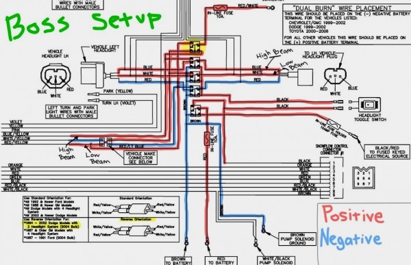
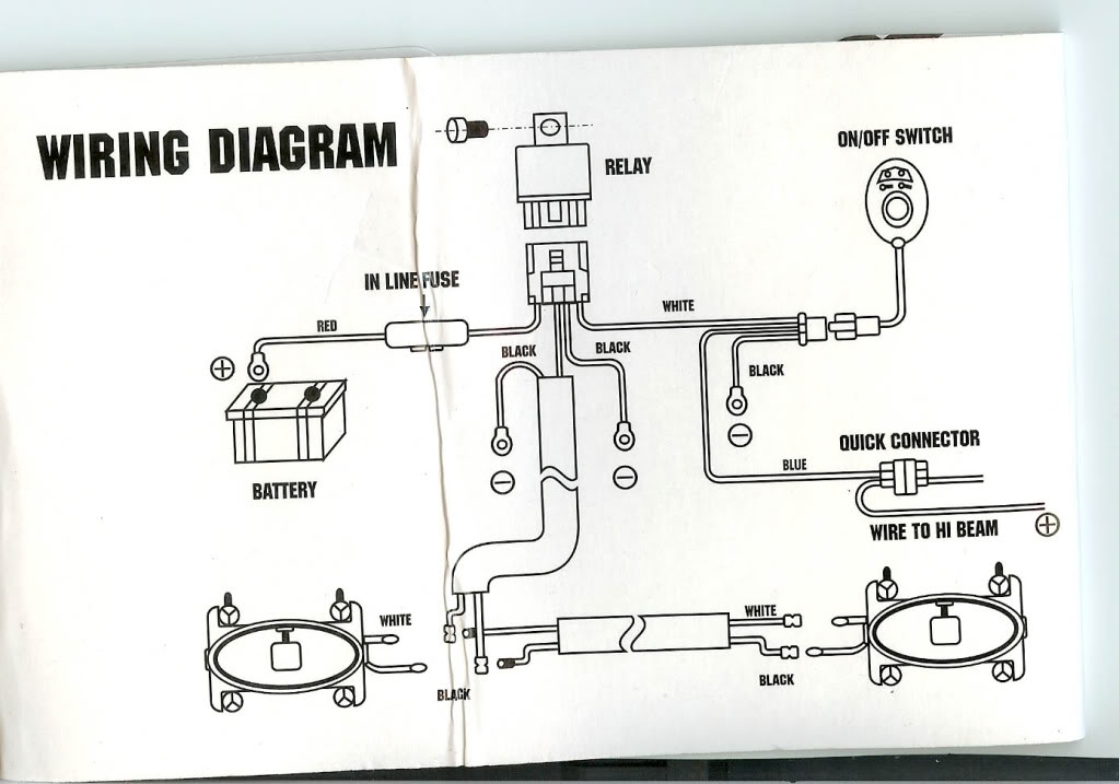
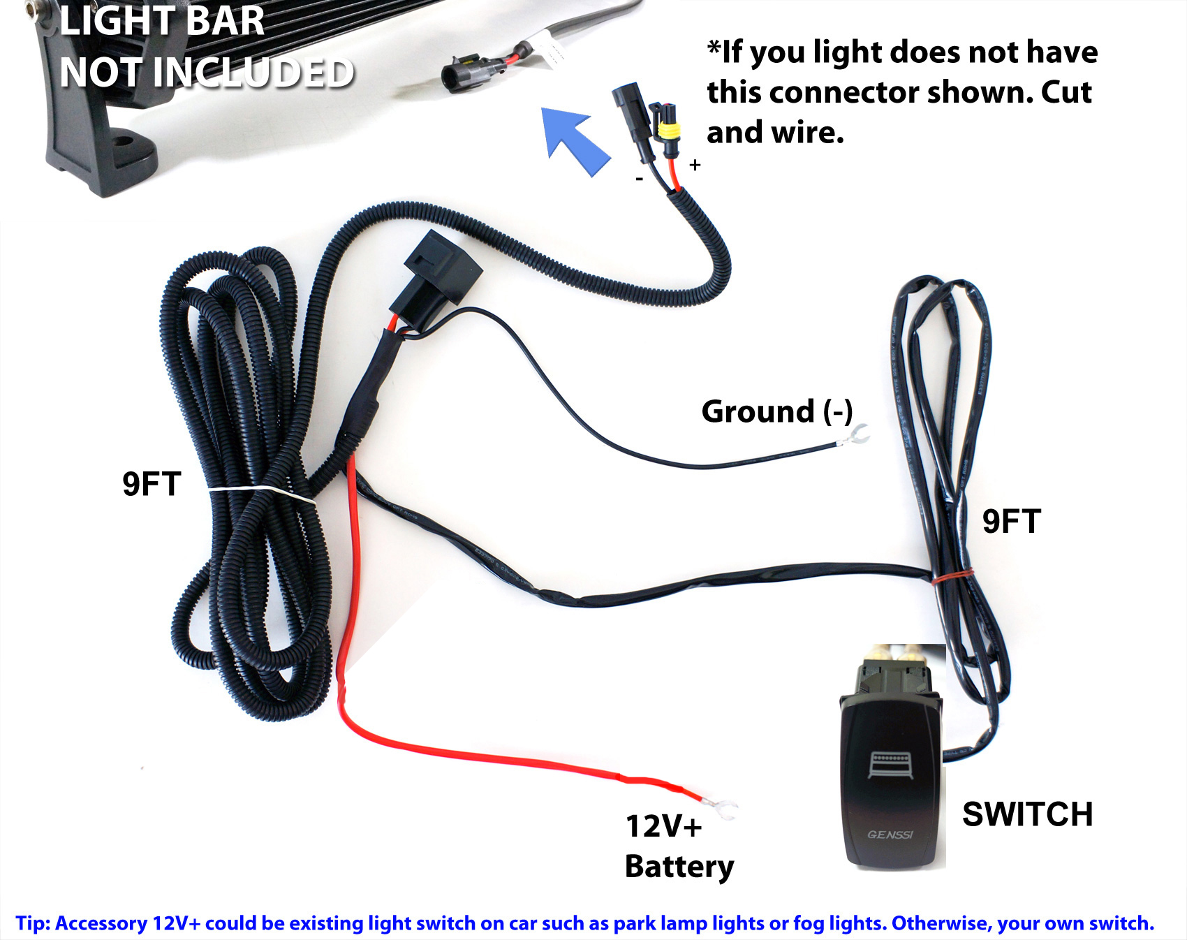
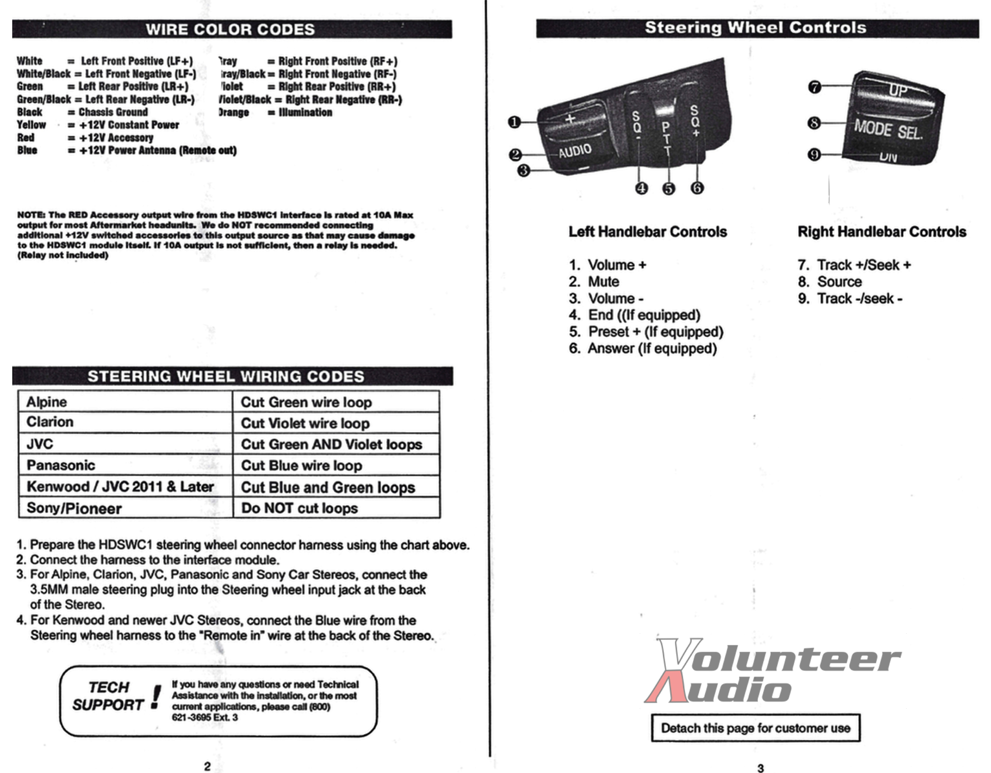
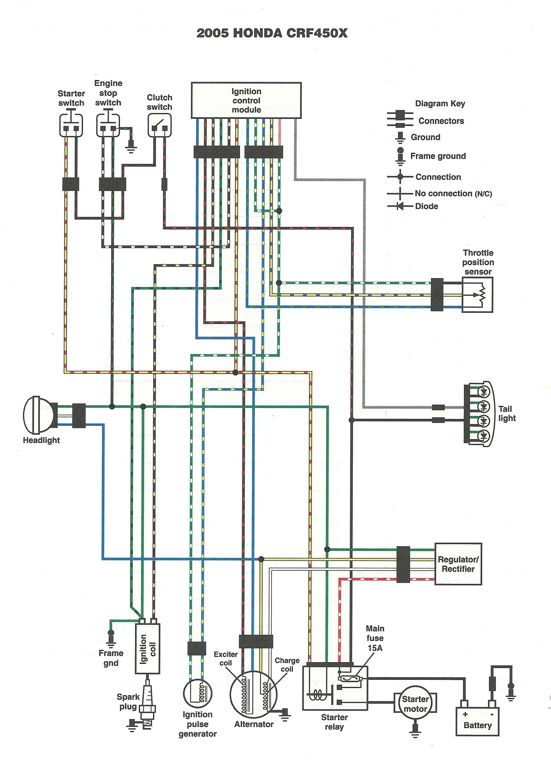
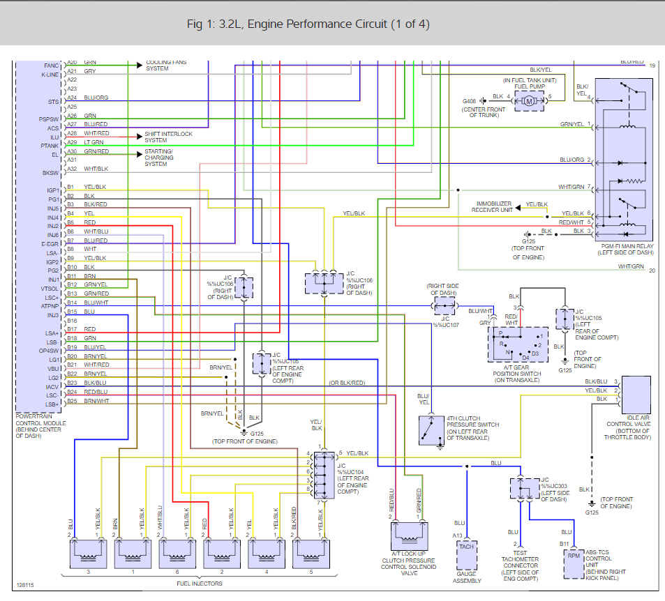
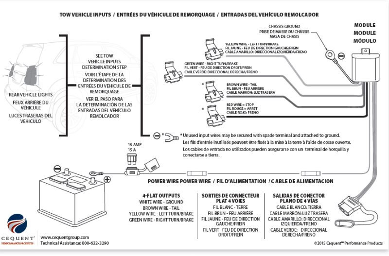
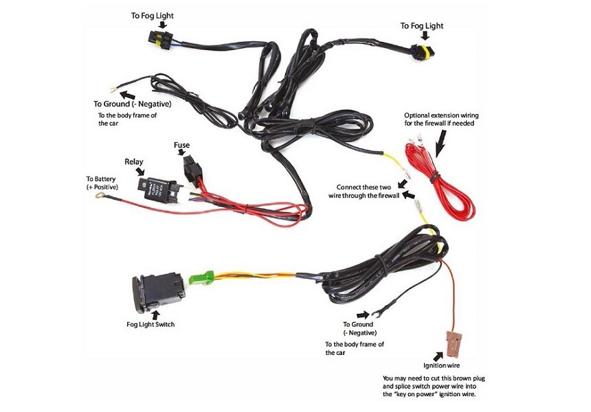
aftermarket-wiring-harness-install-wiring-diagram.pdf
1 / 91
100%
Download Full Diagram Via this App!!!!
Get Diagram Now! DOWNLOAD NOW
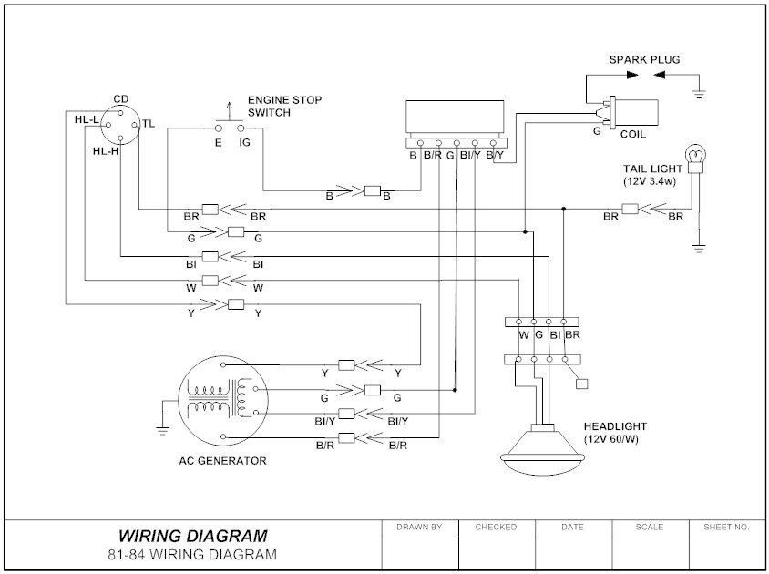
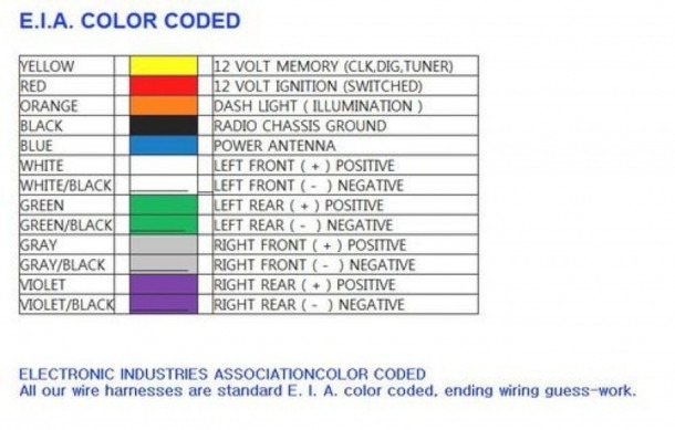
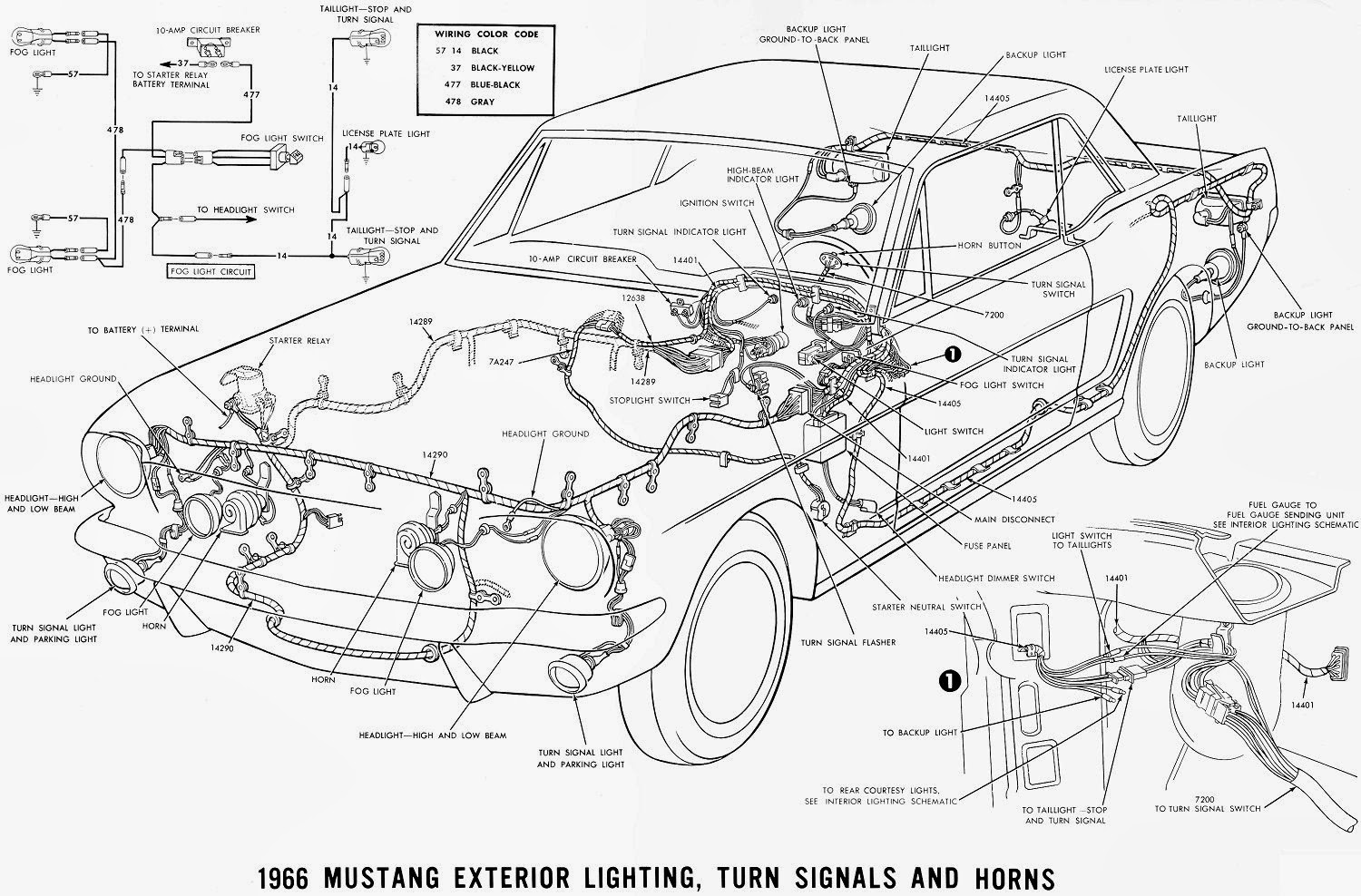
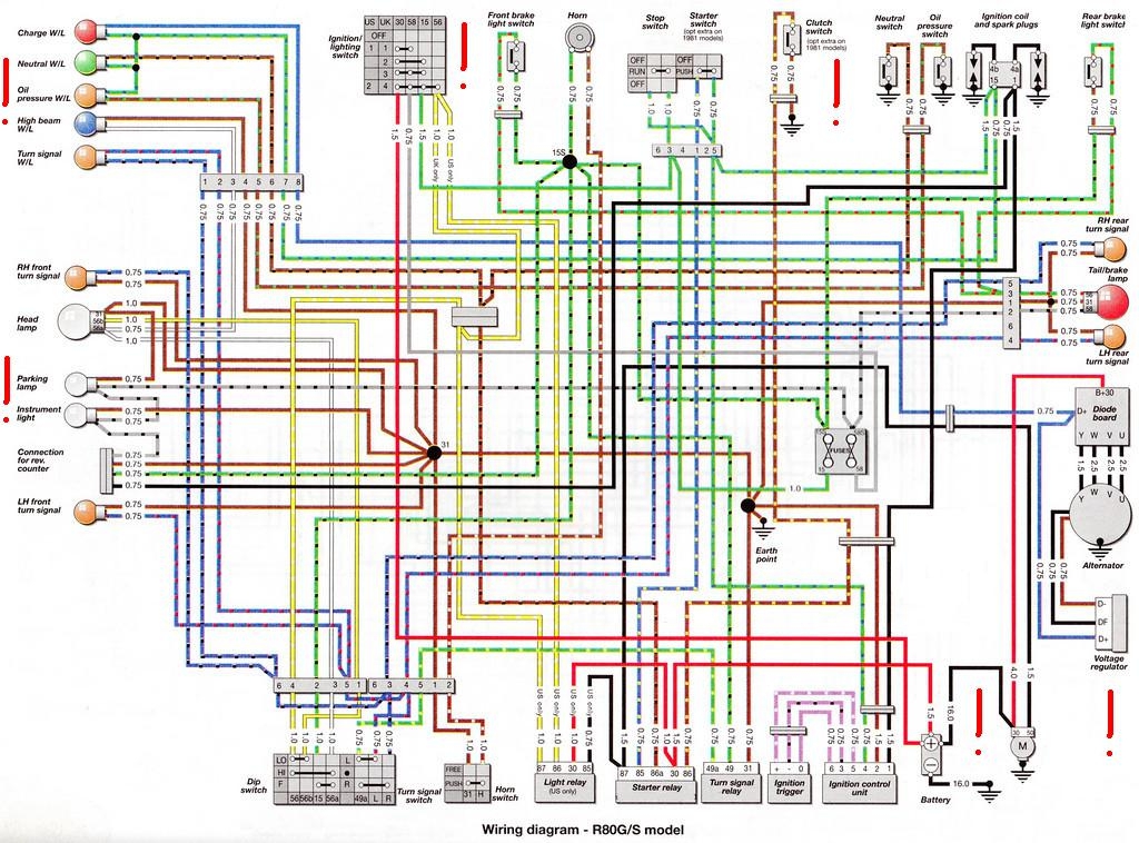
 Title : Aftermarket Wiring Harness Install Wiring Diagram
Category : Wiring Diagram
Format : PDF
Title : Aftermarket Wiring Harness Install Wiring Diagram
Category : Wiring Diagram
Format : PDF