96-ford-mustang-fuse-box-diagram.pdf
1 / 98
100%
Download Full Diagram Via this App!!!!
Get Diagram Now! DOWNLOAD NOW
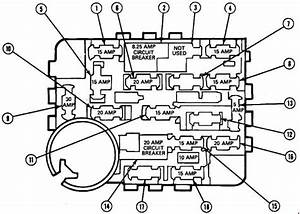 Title : 96 Ford Mustang Fuse Box Diagram
Category : Box Diagram
Format : PDF
Title : 96 Ford Mustang Fuse Box Diagram
Category : Box Diagram
Format : PDF