48-u0026quot-wire-harness-4-way-flat-connector-car-end-wiring-diagram.pdf
1 / 81
100%
Download Full Diagram Via this App!!!!
Get Diagram Now! DOWNLOAD NOW
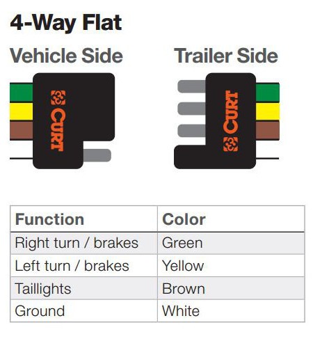
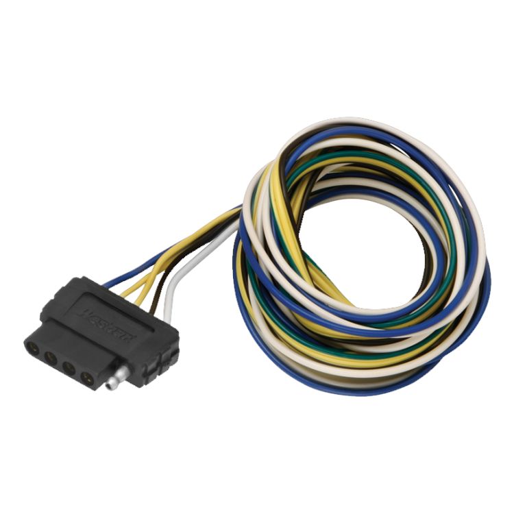
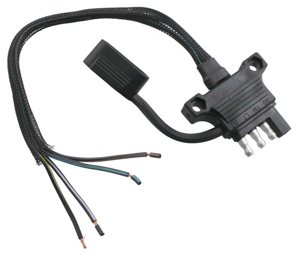
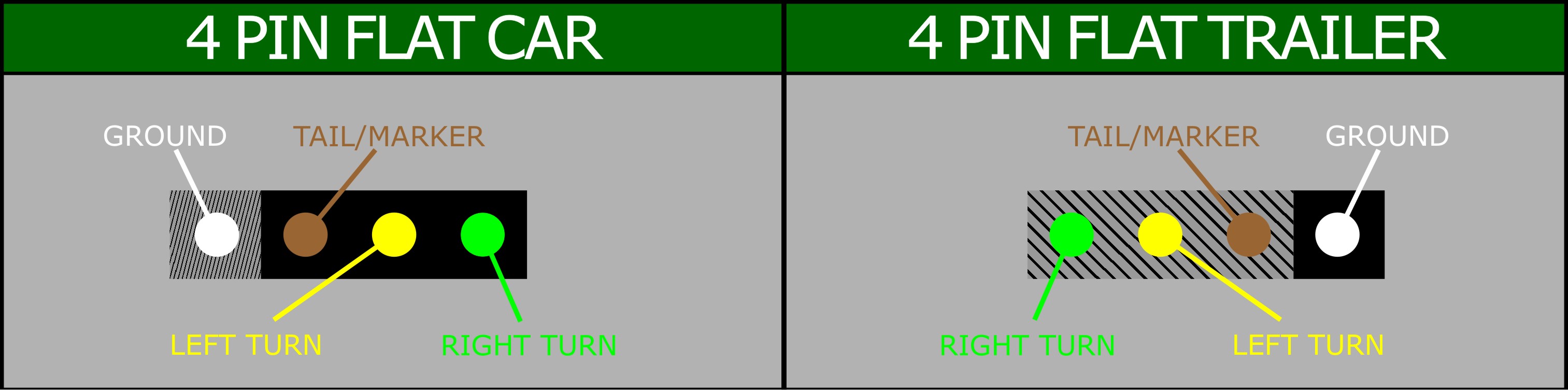
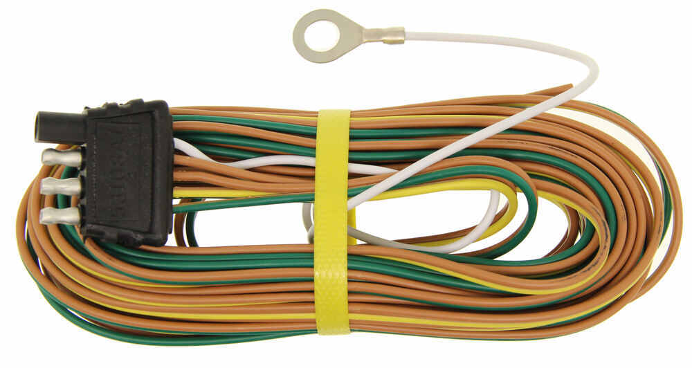
 Title : 48 U0026quot Wire Harness 4 Way Flat Connector Car End Wiring Diagram
Category : Wiring Diagram
Format : PDF
Title : 48 U0026quot Wire Harness 4 Way Flat Connector Car End Wiring Diagram
Category : Wiring Diagram
Format : PDF

.jpg)


%2C445%2C291%2C400%2C400%2Carial%2C12%2C4%2C0%2C0%2C5_SCLZZZZZZZ_.jpg)