2pcs-h4-9003-hb2-wiring-harness-socket-for-4x6-u0026quot-7-u0026quot-x6-u0026quot-5-u0026quot-x7-wiring-diagram.pdf
1 / 88
100%
Download Full Diagram Via this App!!!!
Get Diagram Now! DOWNLOAD NOW
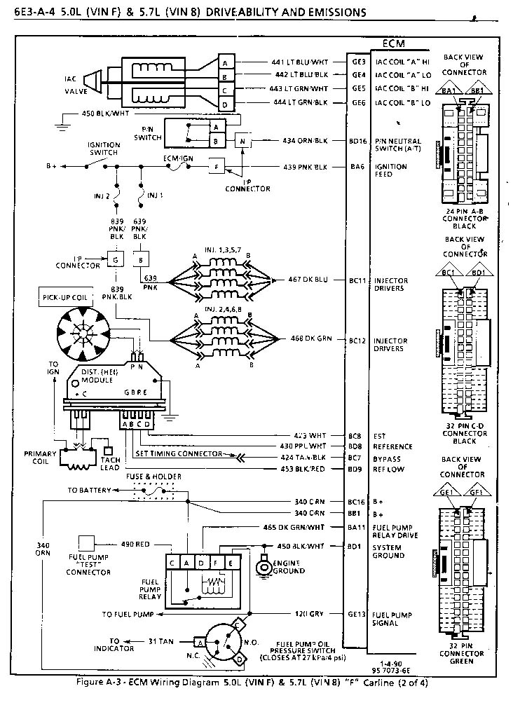
 Title : 2pcs H4 9003 Hb2 Wiring Harness Socket For 4x6 U0026quot 7 U0026quot X6 U0026quot 5 U0026quot X7 Wiring Diagram
Category : Wiring Diagram
Format : PDF
Title : 2pcs H4 9003 Hb2 Wiring Harness Socket For 4x6 U0026quot 7 U0026quot X6 U0026quot 5 U0026quot X7 Wiring Diagram
Category : Wiring Diagram
Format : PDF