2009-nissan-altima-engine-diagram.pdf
1 / 83
100%
Download Full Diagram Via this App!!!!
Get Diagram Now! DOWNLOAD NOW
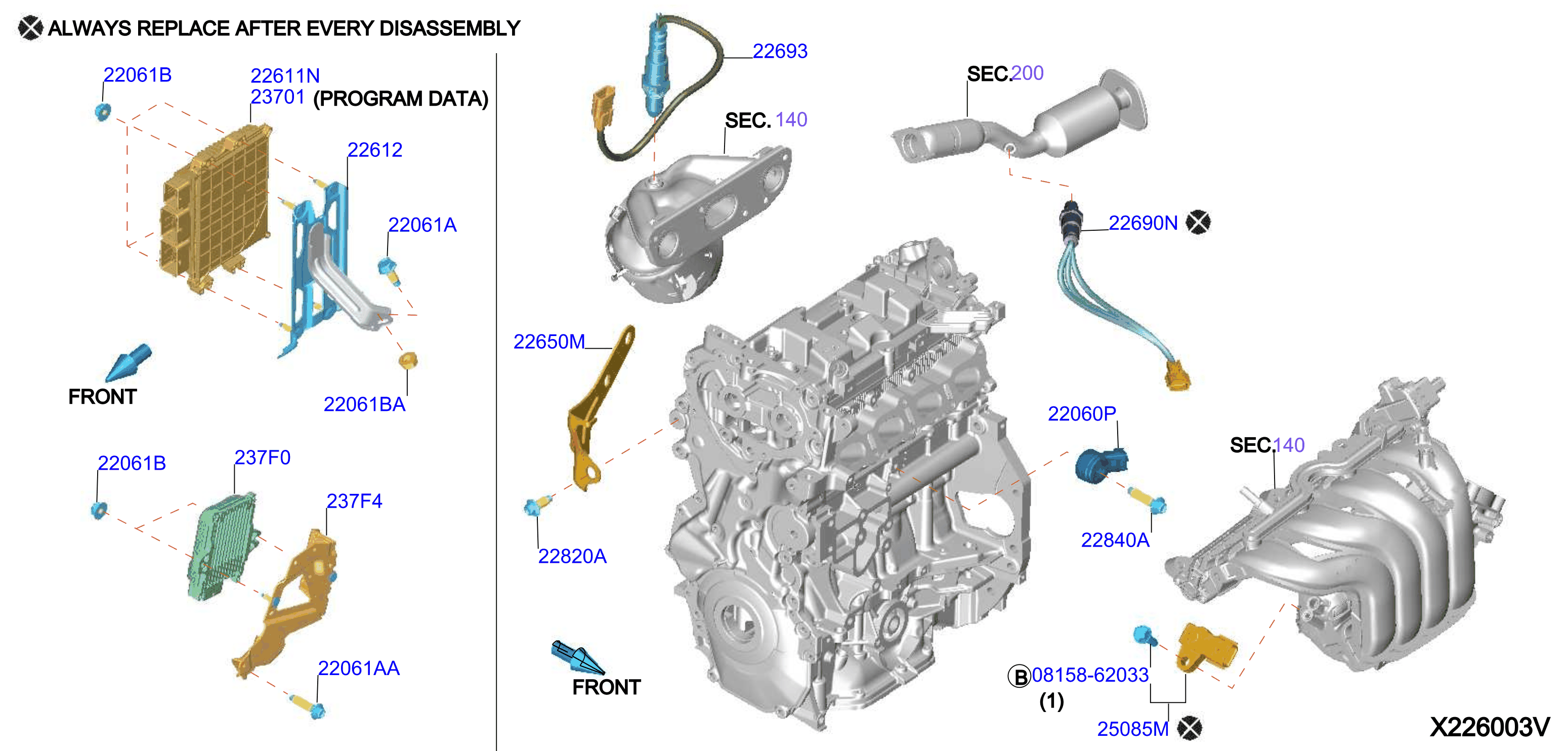
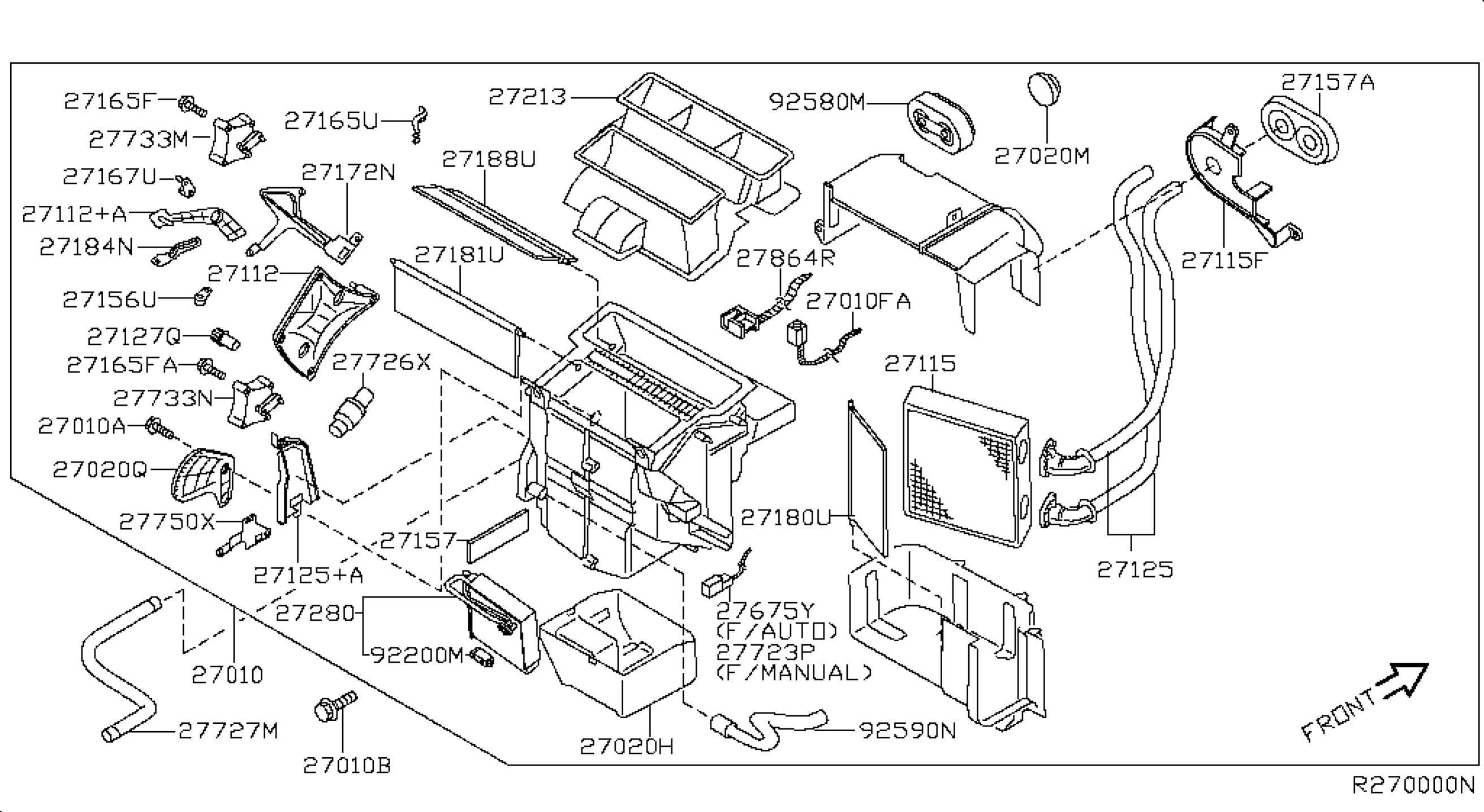
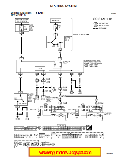
 Title : 2009 Nissan Altima Engine Diagram
Category : Engine Diagram
Format : PDF
Title : 2009 Nissan Altima Engine Diagram
Category : Engine Diagram
Format : PDF