2007-chevy-silverado-1500-fuse-diagram.pdf
1 / 82
100%
Download Full Diagram Via this App!!!!
Get Diagram Now! DOWNLOAD NOW
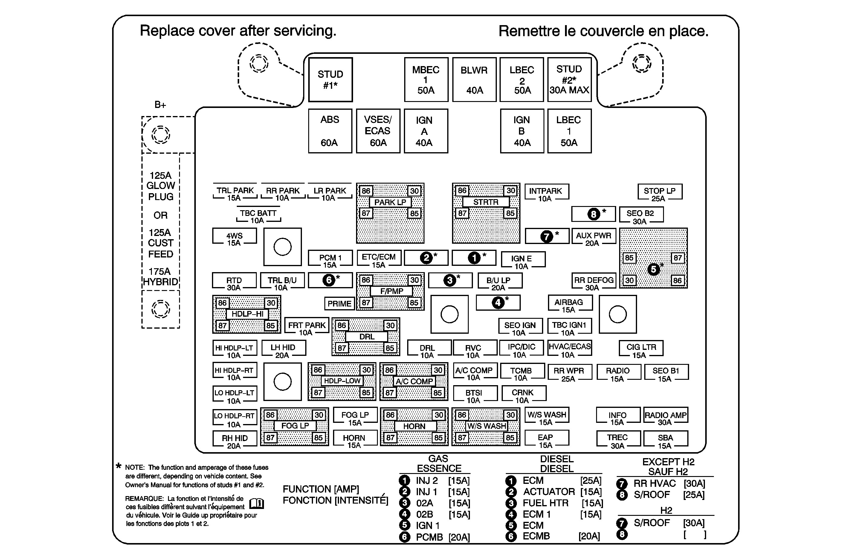
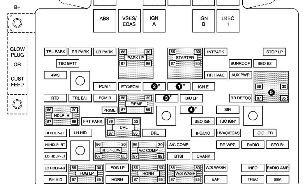
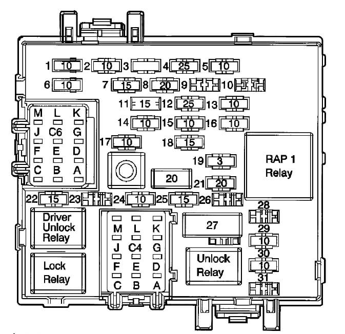
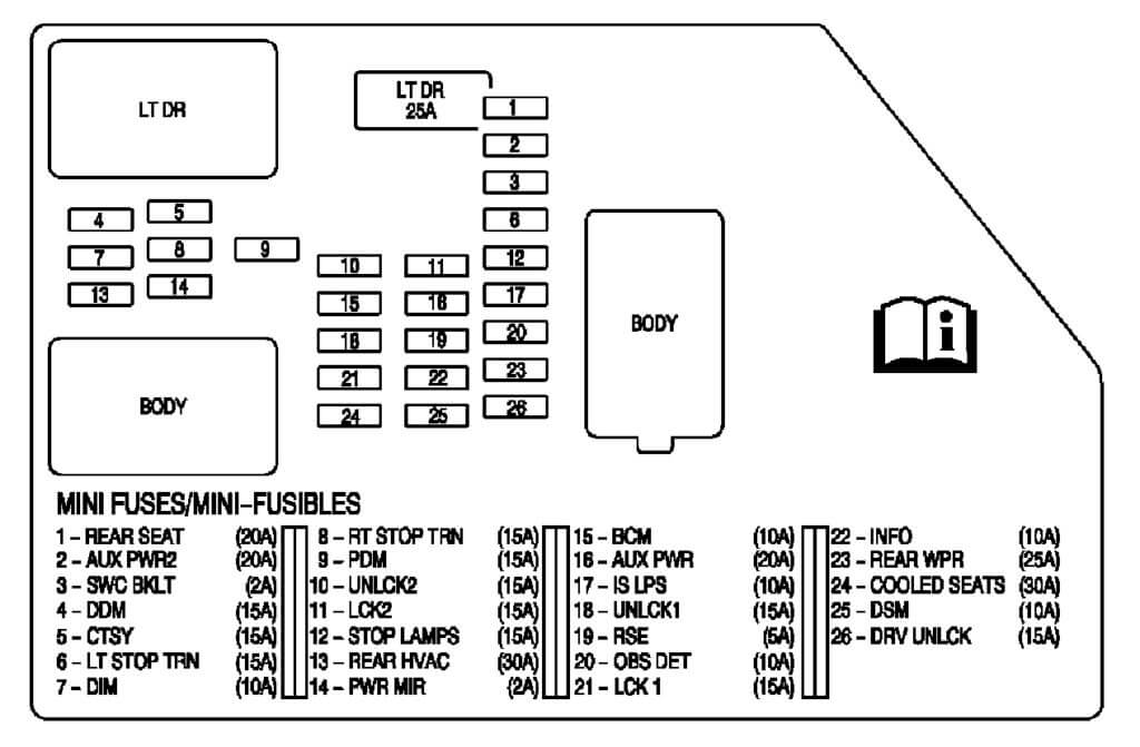
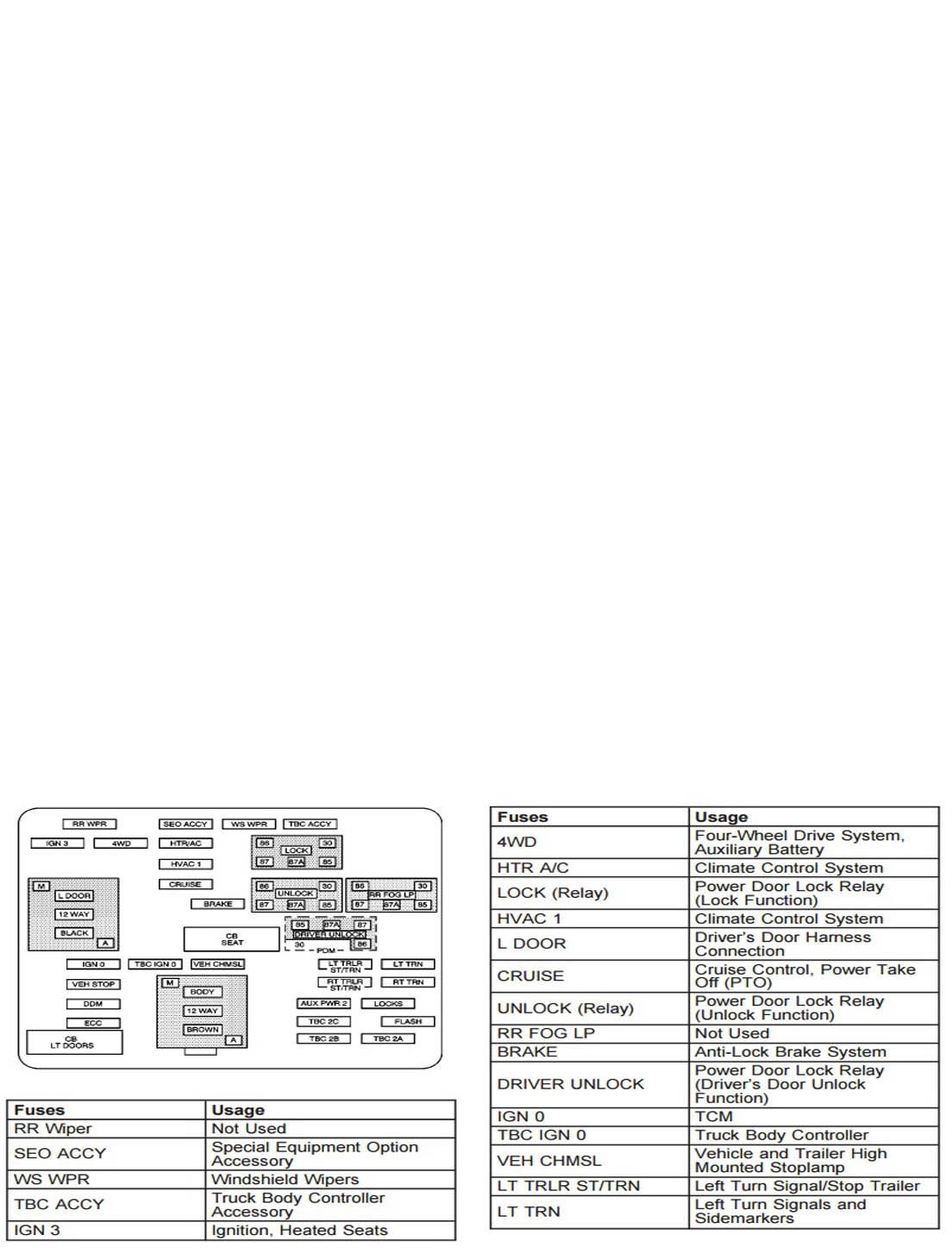
 Title : 2007 Chevy Silverado 1500 Fuse Diagram
Category : Fuse Diagram
Format : PDF
Title : 2007 Chevy Silverado 1500 Fuse Diagram
Category : Fuse Diagram
Format : PDF