2004-pontiac-grand-am-electrical-diagram.pdf
1 / 96
100%
Download Full Diagram Via this App!!!!
Get Diagram Now! DOWNLOAD NOW
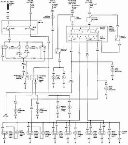 Title : 2004 Pontiac Grand Am Electrical Diagram
Category : Electrical Diagram
Format : PDF
Title : 2004 Pontiac Grand Am Electrical Diagram
Category : Electrical Diagram
Format : PDF