2001-jeep-grand-cherokee-information-wiring-diagram.pdf
1 / 80
100%
Download Full Diagram Via this App!!!!
Get Diagram Now! DOWNLOAD NOW
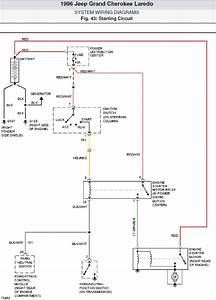 Title : 2001 Jeep Grand Cherokee Information Wiring Diagram
Category : Wiring Diagram
Format : PDF
Title : 2001 Jeep Grand Cherokee Information Wiring Diagram
Category : Wiring Diagram
Format : PDF