1999-ezgo-golf-cart-wiring-diagram.pdf
1 / 85
100%
Download Full Diagram Via this App!!!!
Get Diagram Now! DOWNLOAD NOW
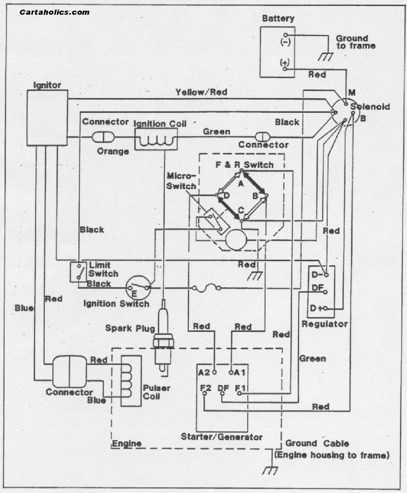
 Title : 1999 Ezgo Golf Cart Wiring Diagram
Category : Wiring Diagram
Format : PDF
Title : 1999 Ezgo Golf Cart Wiring Diagram
Category : Wiring Diagram
Format : PDF