1996-kawasaki-vulcan-800-ignition-coil-wiring-diagram.pdf
1 / 96
100%
Download Full Diagram Via this App!!!!
Get Diagram Now! DOWNLOAD NOW
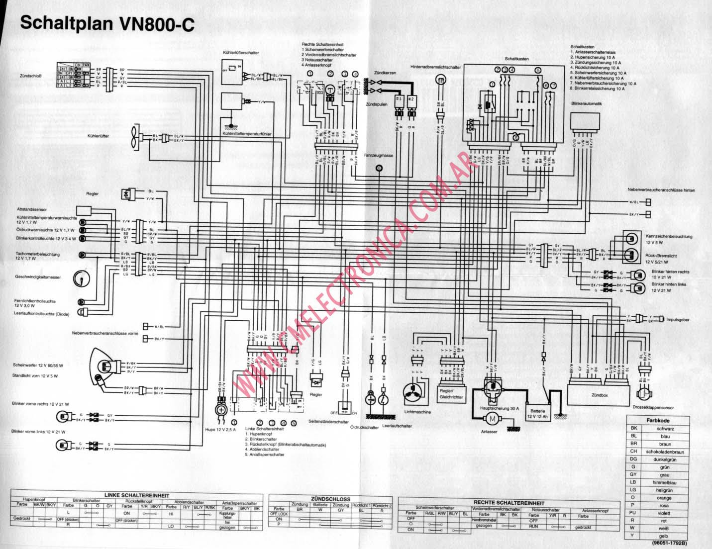
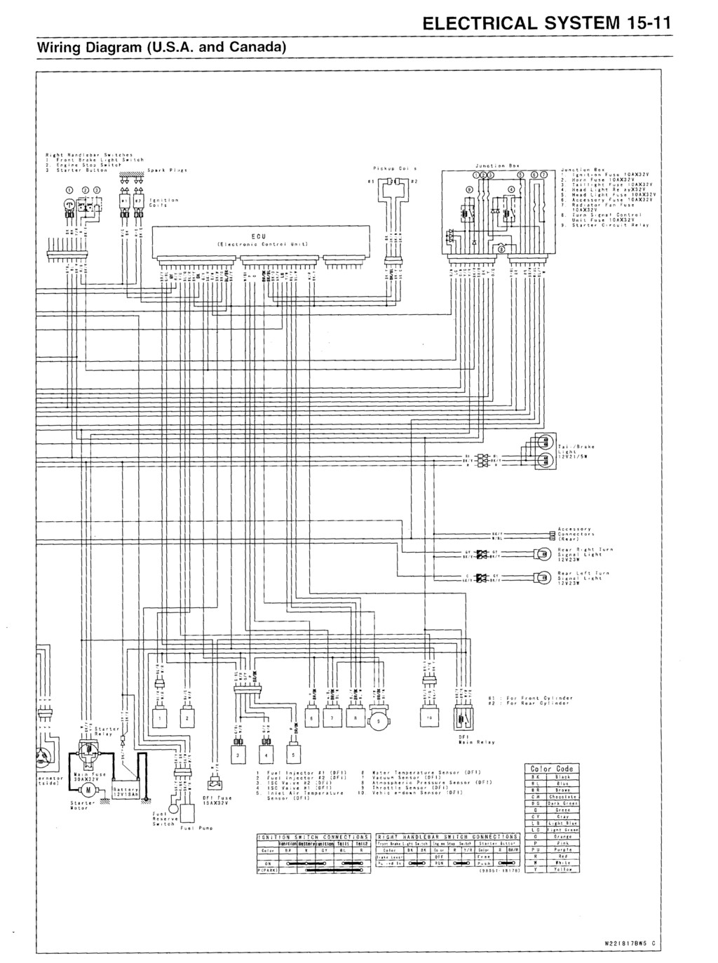
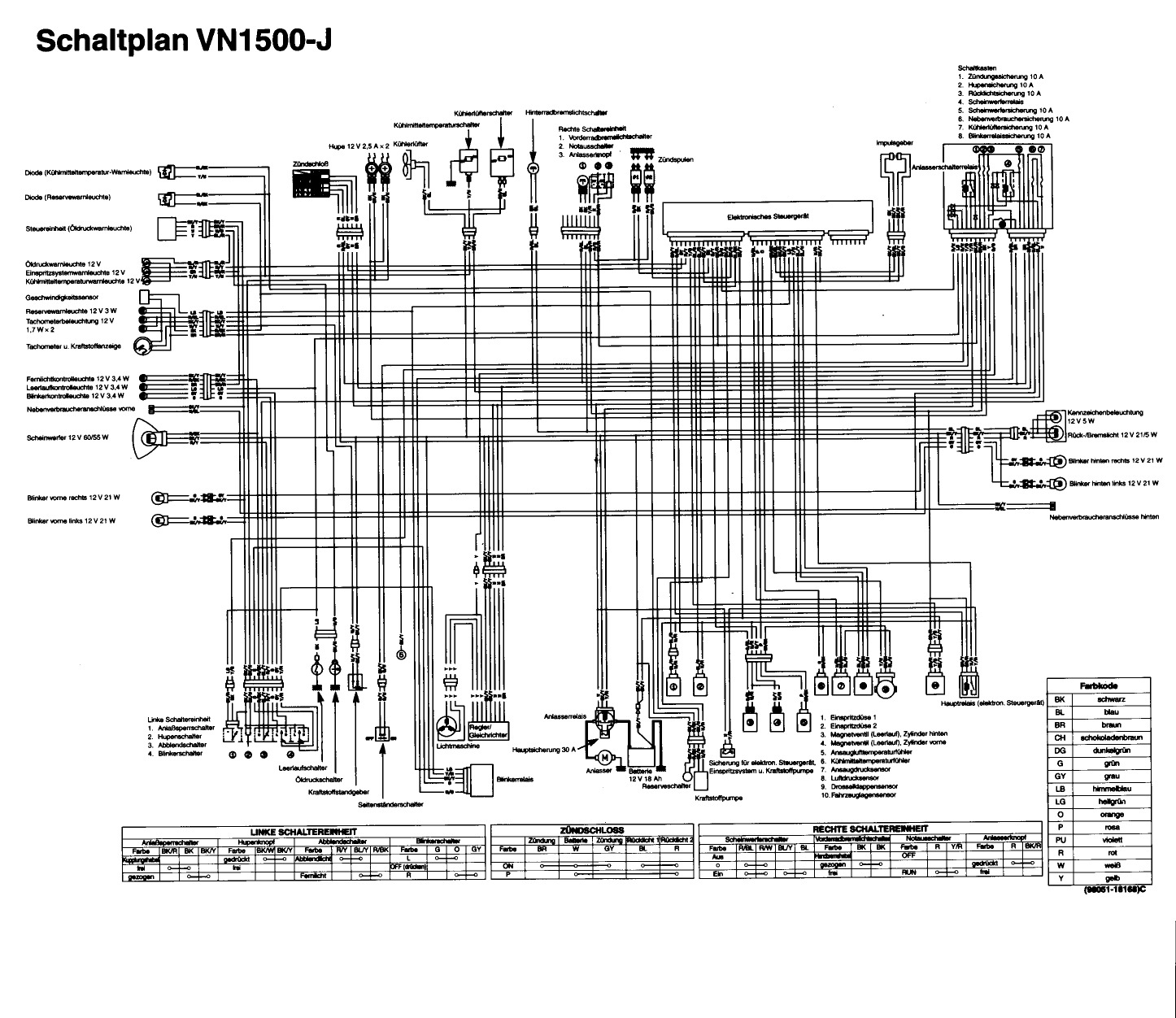
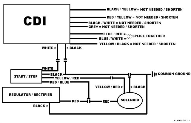
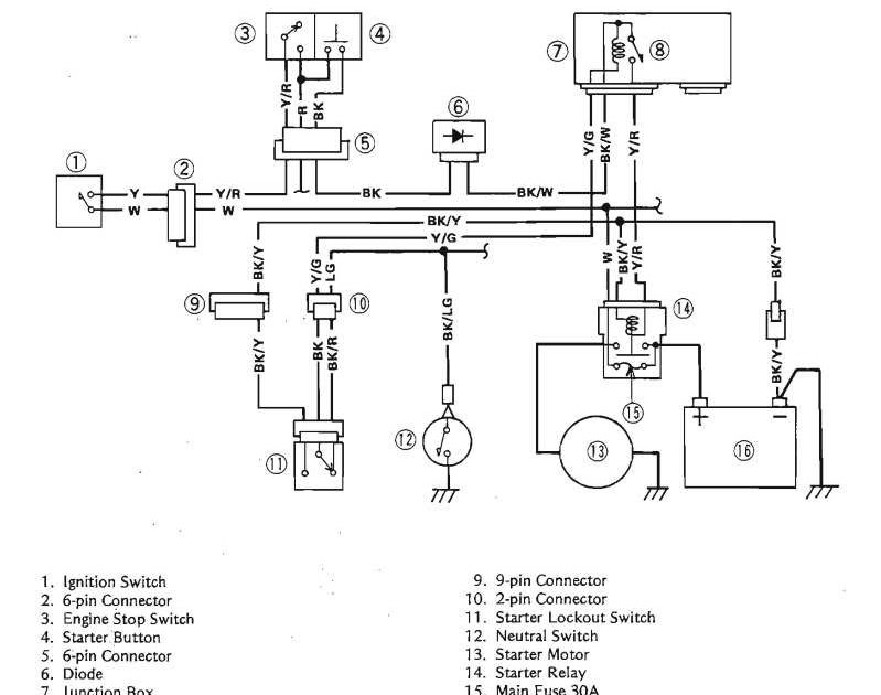
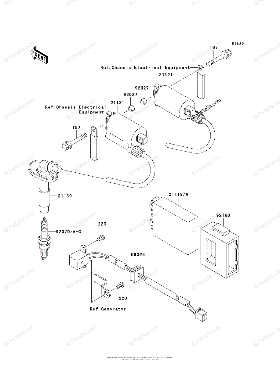
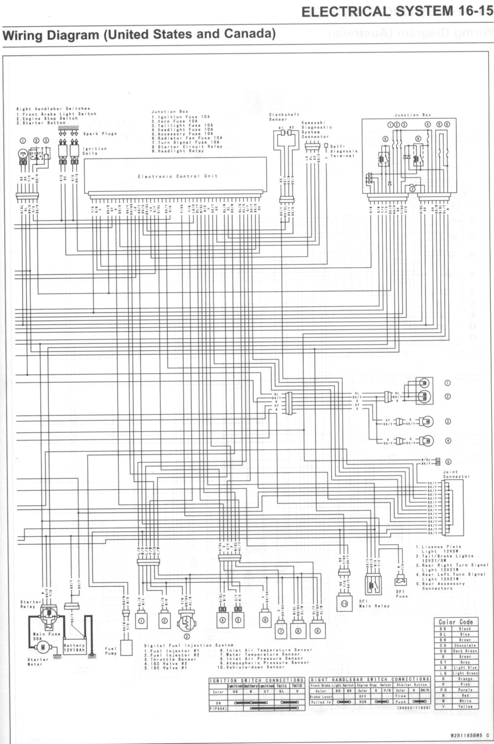
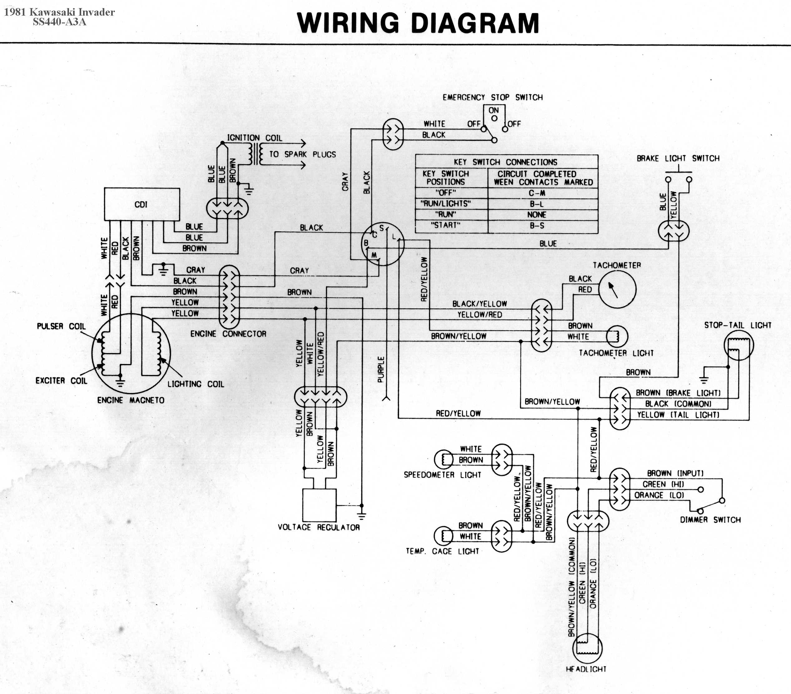
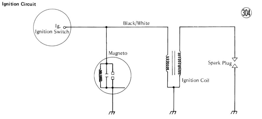
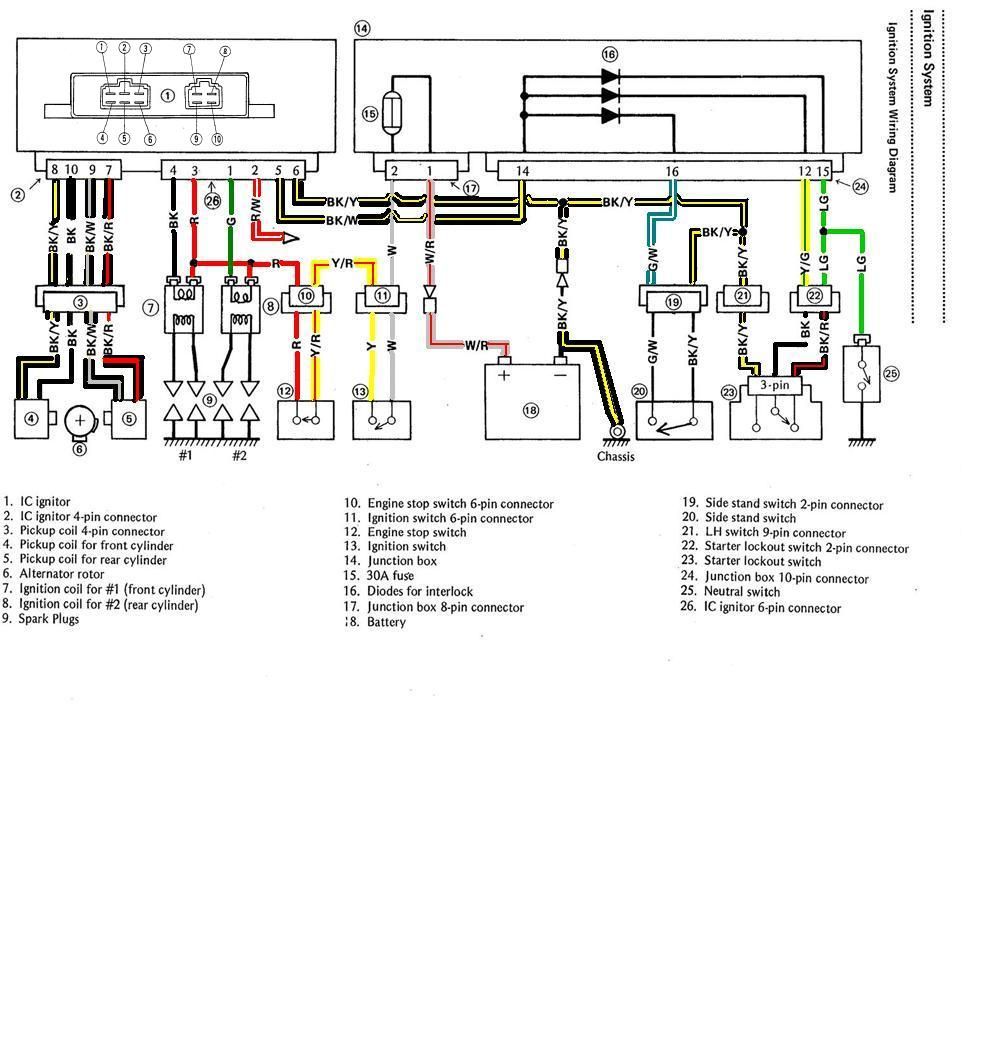
 Title : 1996 Kawasaki Vulcan 800 Ignition Coil Wiring Diagram
Category : Wiring Diagram
Format : PDF
Title : 1996 Kawasaki Vulcan 800 Ignition Coil Wiring Diagram
Category : Wiring Diagram
Format : PDF