1985-nissan-pickup-wiring-diagram.pdf
1 / 98
100%
Download Full Diagram Via this App!!!!
Get Diagram Now! DOWNLOAD NOW
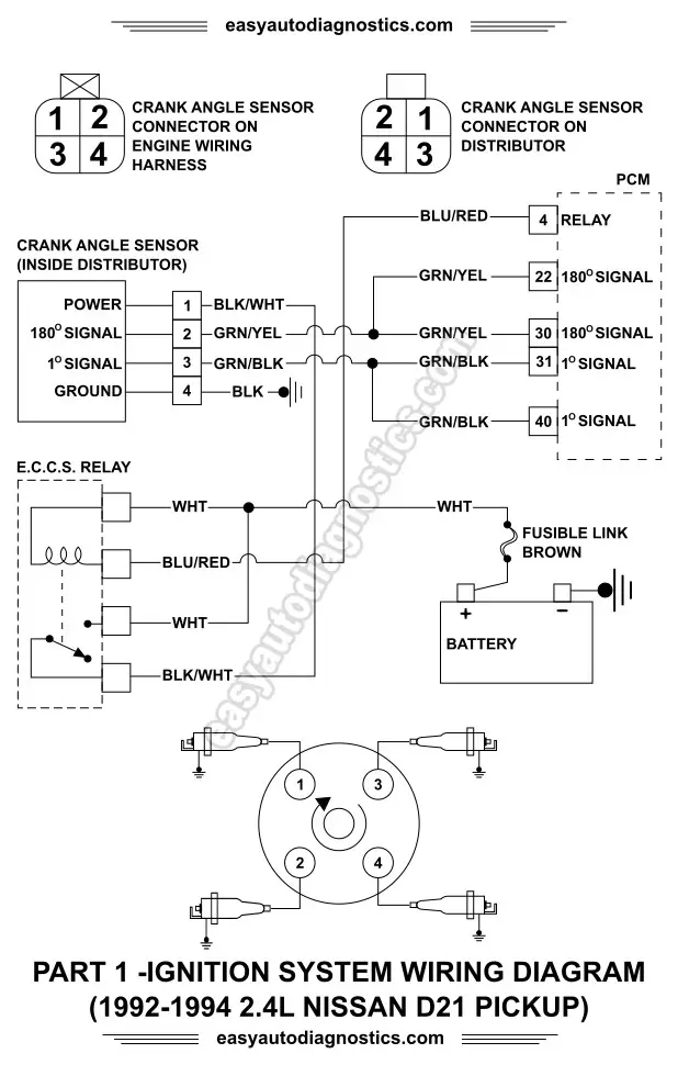
 Title : 1985 Nissan Pickup Wiring Diagram
Category : Wiring Diagram
Format : PDF
Title : 1985 Nissan Pickup Wiring Diagram
Category : Wiring Diagram
Format : PDF