diagram-71-alfa-romeo-wiring-diagram-full-version-hd-wiring-diagram.pdf
1 / 95
100%
Download Full Diagram Via this App!!!!
Get Diagram Now! DOWNLOAD NOW
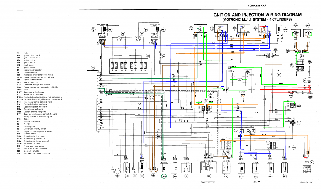
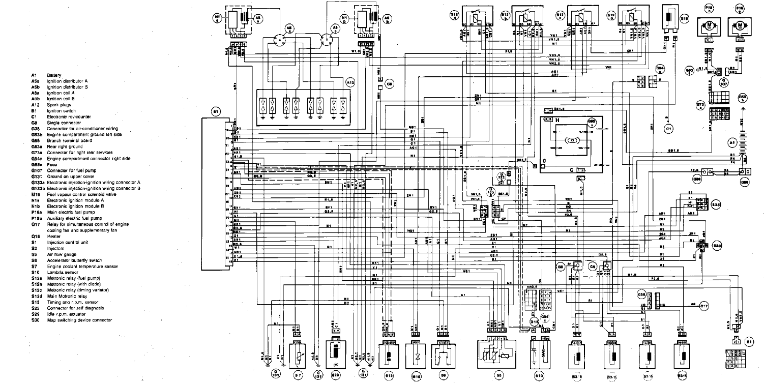
 Title : Diagram 71 Alfa Romeo Wiring Diagram Full Version Hd Wiring Diagram
Category : Wiring Diagram
Format : PDF
Title : Diagram 71 Alfa Romeo Wiring Diagram Full Version Hd Wiring Diagram
Category : Wiring Diagram
Format : PDF