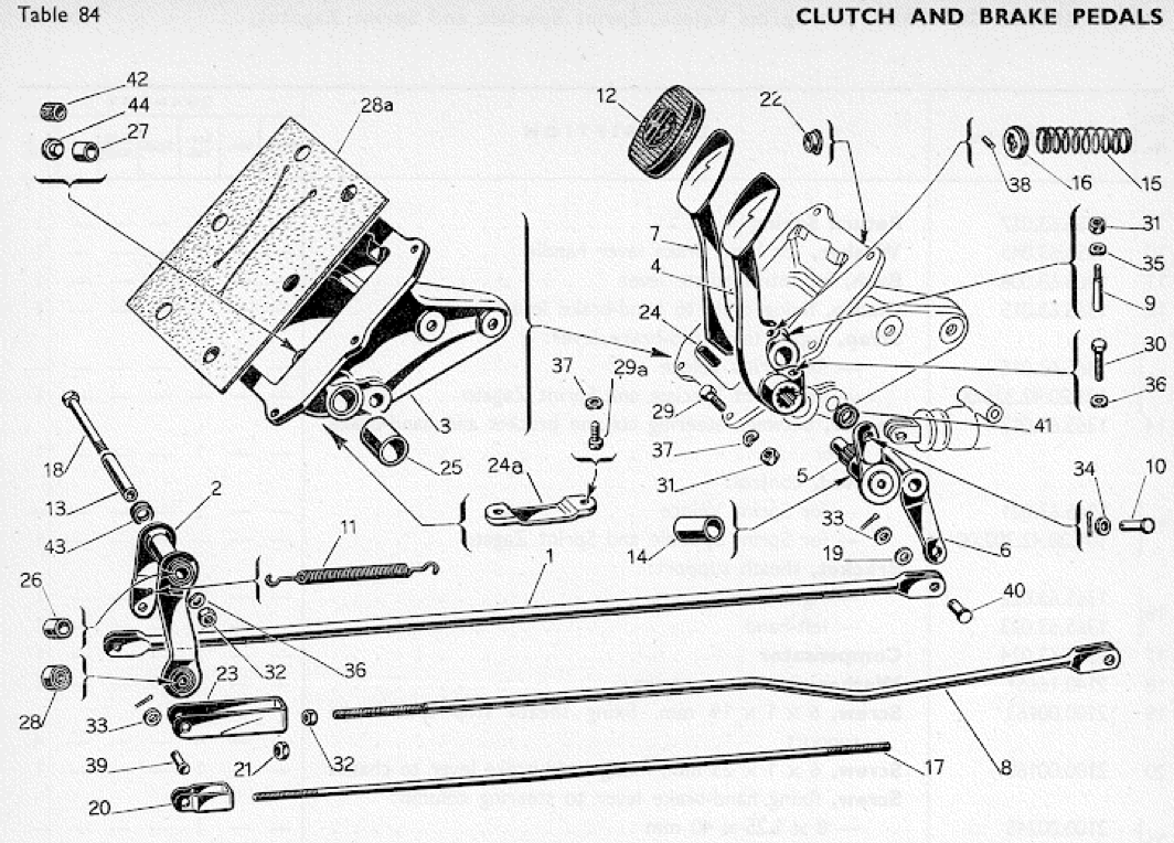
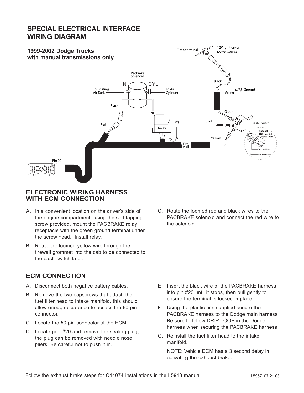
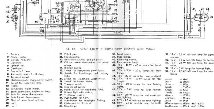
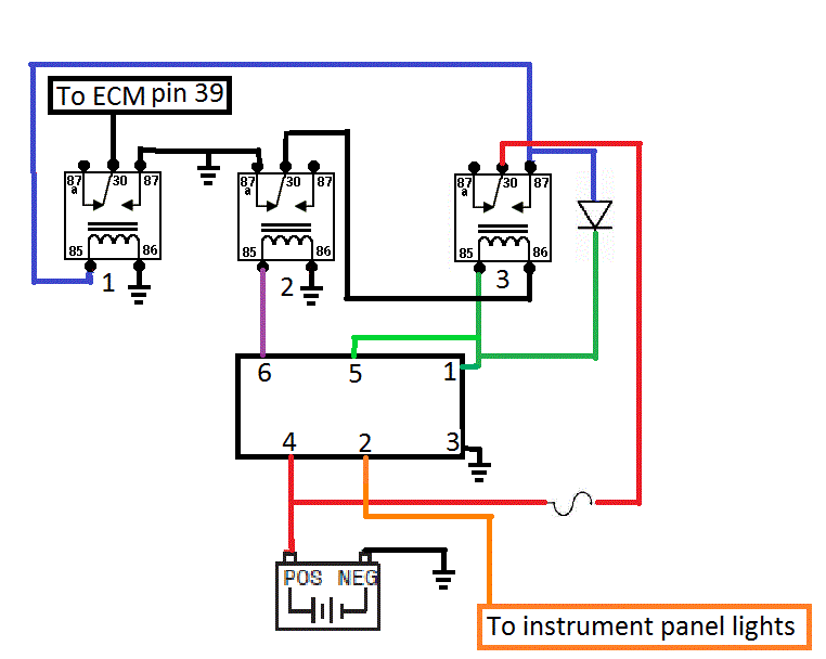
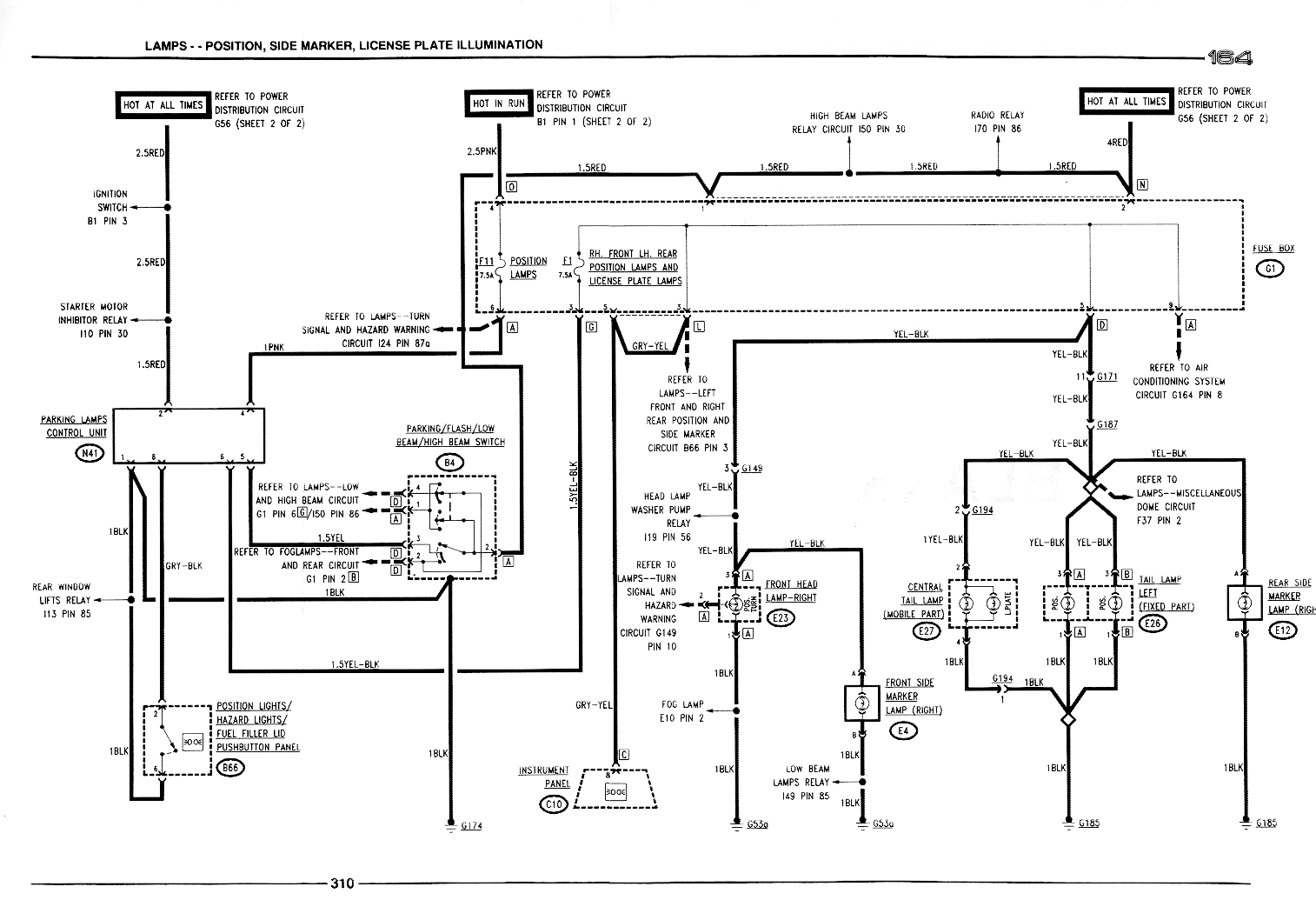
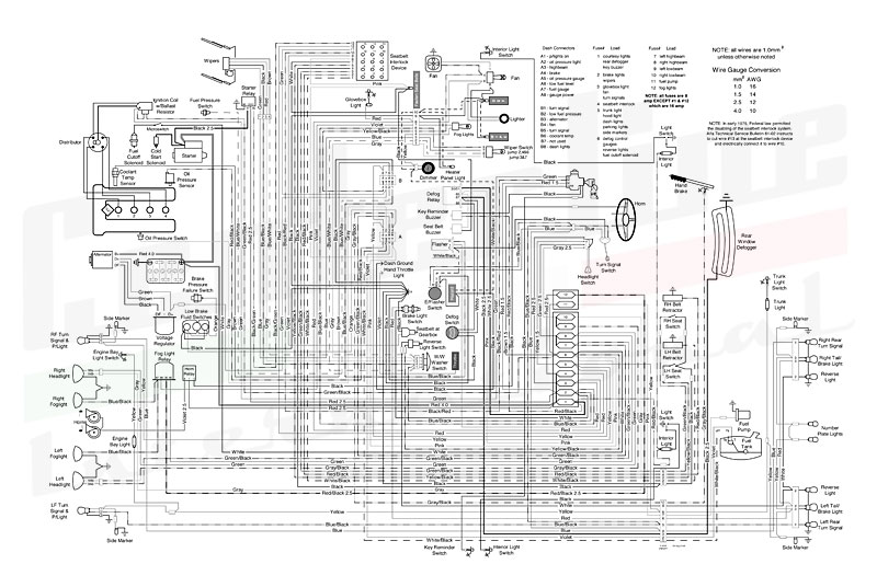
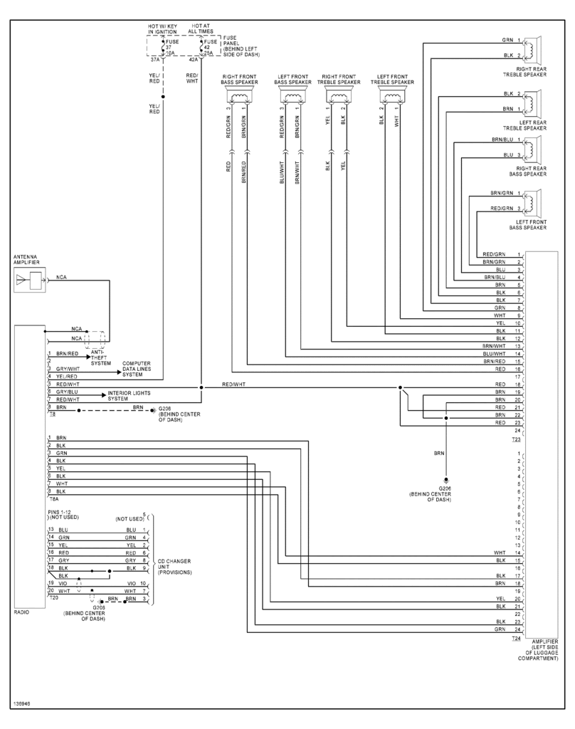
85-spider-veloce-wiring-diagram-wiring-diagram.pdf
100%

85 Spider Veloce Wiring Diagram Wiring Diagram


HTTP://MYDIAGRAM.ONLINE
Revision 2.9 (04/2008)
© 2008 HTTP://MYDIAGRAM.ONLINE. All Rights Reserved.

TABLE OF CONTENTS

Cover1
Table of Contents2
Introduction & Scope3
Safety and Handling4
Symbols & Abbreviations5
Wire Colors & Gauges6
Power Distribution Overview7
Grounding Strategy8
Connector Index & Pinout9
Sensor Inputs10
Actuator Outputs11
Control Unit / Module12
Communication Bus13
Protection: Fuse & Relay14
Test Points & References15
Measurement Procedures16
Troubleshooting Guide17
Common Fault Patterns18
Maintenance & Best Practices19
Appendix & References20
Deep Dive #1 - Signal Integrity & EMC21
Deep Dive #2 - Signal Integrity & EMC22
Deep Dive #3 - Signal Integrity & EMC23
Deep Dive #4 - Signal Integrity & EMC24
Deep Dive #5 - Signal Integrity & EMC25
Deep Dive #6 - Signal Integrity & EMC26
Harness Layout Variant #127
Harness Layout Variant #228
Harness Layout Variant #329
Harness Layout Variant #430
Diagnostic Flowchart #131
Diagnostic Flowchart #232
Diagnostic Flowchart #333
Diagnostic Flowchart #434
Case Study #1 - Real-World Failure35
Case Study #2 - Real-World Failure36
Case Study #3 - Real-World Failure37
Case Study #4 - Real-World Failure38
Case Study #5 - Real-World Failure39
Case Study #6 - Real-World Failure40
Hands-On Lab #1 - Measurement Practice41
Hands-On Lab #2 - Measurement Practice42
Hands-On Lab #3 - Measurement Practice43
Hands-On Lab #4 - Measurement Practice44
Hands-On Lab #5 - Measurement Practice45
Hands-On Lab #6 - Measurement Practice46
Checklist & Form #1 - Quality Verification47
Checklist & Form #2 - Quality Verification48
Checklist & Form #3 - Quality Verification49
Checklist & Form #4 - Quality Verification50
Introduction & Scope Page 3

No electrical installation is truly safe without proper grounding. It equalizes potentials, shields equipment, and safeguards operators. Yet despite its importance, grounding is often ignored or misunderstood, leading to noise interference, hidden faults, and dangerous failures. A sound grounding strategy forms the core of both protection and performance in any electrical network.

### **Purpose of Grounding**

At its simplest, grounding creates a common electrical reference among all metal parts. Without a defined zero potential, voltage can float unpredictably, resulting in hazardous currents and erratic operation. By connecting metal frames, enclosures, and reference nodes to the ground, excess current from faults and transients flows safely to ground instead of through sensitive circuits or operators.

Grounding fulfills three primary roles:
1. **Personnel Protection:** Limits touch voltage and ensures operator protection.
2. **Equipment Protection:** Diverts fault current away from devices.
3. **Signal Integrity:** Minimizes noise and interference in control and communication circuits.

### **Types of Grounding Systems**

Different applications and infrastructures demand specific grounding methods:

- **TN Systems (Terra Neutral):** Used in buildings and industrial plants, where neutral is grounded at the source and protective earth is run throughout. Variants such as separate or combined neutral-earth layouts define different grounding topologies.
- **TT Systems:** Each installation has its own earth electrode, isolated from the supply neutral. This design enhances fault isolation but requires RCDs.
- **IT Systems:** Neutral is isolated or impedance-grounded, allowing continued operation after a single fault. Found in hospitals, ships, or critical manufacturing.

Selection depends on safety priority versus uptime.

### **Design Principles**

An effective grounding system begins with low-resistance earth electrodes. Target resistance is typically below industry thresholds, though data centers and power plants may require ultra-low resistance. environmental factors directly affect performance; engineers often improve conductivity using chemical rods or conductive backfill.

**Bonding** links all metallic partsframes, conduits, trays, and structuresinto a single equipotential system. Bonding conductors must be low-inductance and mechanically robust, with clean terminations to prevent corrosion. Mesh grounding works for large, fault-tolerant grids.

**Ground loops** occur when different grounding points create circulating currents, injecting noise into signal lines. The cure is proper analog/digital ground separation joined at one node. For high-frequency circuits, use flat conductors with minimal impedance.

### **System Stability and Noise Control**

A solid grounding design enhances both protection and EMC performance. Power electronics, VFDs, and communication lines generate high-frequency interference that couples into nearby wiring. Shielding and grounding work in synergy to neutralize unwanted radiation. Use 360° terminations for braid grounds, and single-ended grounding for sensitive analog circuits.

Integration with surge arresters is essential. Lightning currents and transient surges must flow directly into earth. Without low inductance, the surge rebounds, damaging electronics.

### **Testing and Maintenance**

Even the best earthing setups age and weaken. Corrosion, loosening, and soil drying increase resistance. Periodic testing using earth-resistance meters or clamp testers ensures consistent protection levels.

In critical sitesdata centers, refineries, and airportsmonitoring is often continuous. Ground-potential sensors and alarms detect imbalances between equipment frame and earth. Maintenance teams log results, trend data, and adjust proactively.

### **Integration with Modern Design**

Todays smart systems combine earthing with IoT monitoring. Sensors in switchgear, busbars, and panels record real-time performance data. Software then visualizes earthing conditions, helping engineers locate weak points instantly.

As solar, battery, and hybrid grids expand, grounding strategies evolve. Battery banks and DC buses require different bonding for mixed AC/DC systems. International standards such as renewable safety frameworks define how hybrid circuits remain safe and grid-compliant.

### **Conclusion**

Grounding is not just a safety accessory; its the backbone of reliable operation. Proper design ensures current flows where intended, keeping machines operational and operators protected. When maintained with testing and documentation, grounding transforms from simple metal into engineered protection.

Figure 1
Safety and Handling Page 4

Working safely requires both awareness and preparation. Before you start, shut down every source of energy and confirm it with a meter before touching anything. Have PPE ready — shield, gloves, and flame-rated clothing are part of standard practice. Stay focused and never hurry electrical work.

Handling safely is about treating components the way they were designed to be treated. Never make a temporary twist joint; use the correct splice hardware. Use smooth clamps and wide bends so cables are never kinked or pinched. Do not run harnesses next to heat, fuel, or pressurized fluid lines. These mechanical details prevent tomorrow’s electrical failures.

Once repairs are complete, double-check terminal torque and fuse types. Bring power back slowly and watch for abnormal current, noise, or burning smell. Log your adjustments so future techs know exactly what was done. Real safety is prevention plus documentation and final verification.

Figure 2
Symbols & Abbreviations Page 5

In most schematics, physical distance is abstract — two parts drawn side by side may be far apart in real hardware. The icons plus short codes tell you which points are truly linked, even if the hardware is nowhere near each other. That tiny arrow “TO FAN RELAY” on the print could be an actual multi-meter cable run inside “85 Spider Veloce Wiring Diagram Wiring Diagram”.

Abbreviations also describe signal quality and wiring style. Tags like SHIELD or TWISTED PAIR tell you that run is noise‑controlled and must remain protected. Callouts like 5V REF CLEAN or HI SIDE DRV / LO SIDE DRV tell you what kind of drive strategy the circuit uses in Wiring Diagram.

If you’re diagnosing a failure in 2025, those tiny callouts are not optional. If the print says “SHIELD GND AT ECU ONLY,” that means do not ground that shield somewhere else — doing so adds noise and can break sensor accuracy for “85 Spider Veloce Wiring Diagram Wiring Diagram”. Respecting that instruction protects performance and protects liability for http://mydiagram.online; log what you touched at https://http://mydiagram.online/85-spider-veloce-wiring-diagram-wiring-diagram/ so it’s documented for the next tech.

Figure 3
Wire Colors & Gauges Page 6

Wire color coding and sizing form the essential framework for safe and efficient electrical installations.
Color shows a wire’s function at a glance, while gauge determines its current capacity and physical strength.
Typically, red = live, black/brown = ground, yellow = switch/ignition, and blue = control/signal.
By applying these standards, engineers working on “85 Spider Veloce Wiring Diagram Wiring Diagram” can easily interpret circuits and prevent wiring errors.
Consistent color and size practices improve both safety and serviceability throughout the system lifespan.

Wire gauge describes the conductor’s ability to transmit current safely and efficiently.
A smaller AWG number means a thicker wire that carries more current, while a larger number corresponds to a thinner wire with limited current capacity.
Selecting the correct gauge ensures minimal voltage loss, reduced heating, and better durability.
Across Wiring Diagram, most professionals rely on ISO 6722, SAE J1128, and IEC 60228 standards to maintain quality and uniformity.
Accurate gauge selection keeps components within safe operating limits and prevents premature aging in high-demand circuits like those found in “85 Spider Veloce Wiring Diagram Wiring Diagram”.
Small gauge errors can result in voltage instability, excess heat, or system malfunction.

Documentation brings professionalism and traceability to every wiring task.
Technicians must note all color, size, and connection modifications in inspection logs for future reference.
If alternate paths or wires are installed, proper labeling guarantees clarity for upcoming inspections.
Finished inspection data, schematics, and images should be stored digitally at http://mydiagram.online.
Including date tags (2025) and online reference (https://http://mydiagram.online/85-spider-veloce-wiring-diagram-wiring-diagram/) ensures transparent auditing and traceability.
Detailed record-keeping helps “85 Spider Veloce Wiring Diagram Wiring Diagram” stay compliant, efficient, and professionally maintained for the long term.

Figure 4
Power Distribution Overview Page 7

Effective power distribution guarantees the reliability, safety, and energy efficiency of electrical systems.
It manages the controlled division of energy from a main source into multiple circuits powering “85 Spider Veloce Wiring Diagram Wiring Diagram”.
A proper power network keeps voltage steady, prevents overloads, and safeguards delicate devices.
Poor management can lead to system instability, damaged components, or dangerous short circuits.
Effective distribution design ensures that every part of the system performs at its optimal level under all load conditions.

Planning an efficient power system starts with calculating load distribution and demand.
Wires, relays, and protection devices must be chosen according to load, temperature, and conditions.
In Wiring Diagram, engineers typically refer to ISO 16750, IEC 61000, and SAE J1113 to ensure design consistency and compliance.
Cables carrying high current should be separated from communication or control lines to prevent signal distortion.
Fuses, relays, and ground terminals must be easily accessible and properly organized.
By applying these principles, “85 Spider Veloce Wiring Diagram Wiring Diagram” can maintain efficiency, stability, and resistance to electrical noise across its circuits.

After installation, every power distribution system must undergo testing and validation.
Testing involves measuring voltage stability, circuit continuity, and insulation quality.
Any design adjustments or wiring modifications must be updated in the schematic diagram and maintenance database.
All verification reports, readings, and visual documentation must be archived in http://mydiagram.online.
Including 2025 and https://http://mydiagram.online/85-spider-veloce-wiring-diagram-wiring-diagram/ maintains clear, auditable project records.
Comprehensive validation and logging ensure “85 Spider Veloce Wiring Diagram Wiring Diagram” stays dependable, compliant, and operational.

Figure 5
Grounding Strategy Page 8

It is an essential element of any electrical system, ensuring reliable protection and steady performance.
It provides a direct, low-resistance path for electricity to return safely to the earth, preventing electrical hazards.
Lack of grounding in “85 Spider Veloce Wiring Diagram Wiring Diagram” results in electrical instability, interference, and system crashes.
Strong grounding control keeps voltage levels steady and safeguards equipment from faults.
In summary, grounding establishes a consistent reference point that keeps all electrical operations in Wiring Diagram safe and reliable.

To design an effective grounding system, engineers must calculate soil resistivity, analyze fault current, and determine the optimal electrode layout.
Every connection needs proper insulation, strong fastening, and corrosion protection for longevity.
In Wiring Diagram, compliance with IEC 60364 and IEEE 142 is mandatory to ensure uniformity and safety in grounding installations.
The grounding conductors should be large enough to handle expected current flow and prevent overheating during faults.
All grounding points should interconnect to eliminate potential differences and voltage imbalances.
When implemented correctly, “85 Spider Veloce Wiring Diagram Wiring Diagram” achieves reliable power flow, reduced interference, and long-lasting performance.

Inspection and maintenance play a vital role in preserving the effectiveness of any grounding network.
Inspectors must test resistance, examine electrodes, and ensure all bonds are mechanically sound.
If corrosion or damage is found, immediate replacement and verification are necessary.
Test results and maintenance logs should be archived for compliance and traceability.
Testing should occur at least once every 2025 to ensure the grounding network performs as expected.
Through proper inspection routines and documentation, “85 Spider Veloce Wiring Diagram Wiring Diagram” maintains safe, stable, and efficient grounding integrity.

Figure 6
Connector Index & Pinout Page 9

85 Spider Veloce Wiring Diagram Wiring Diagram Full Manual – Connector Index & Pinout Reference 2025

Automotive systems use many types of connectors that vary in size, locking style, and pin count. Each design serves to ensure secure signal paths and mechanical strength under harsh conditions. They range from small sensor plugs to large ECU couplings that carry critical control signals.

Inline connectors are commonly used to link two harness sections and are often sealed with rubber grommets for water resistance. Complex multi-pin connectors reduce wiring clutter and simplify maintenance. Terminal block connectors handle higher current loads, while sensor connectors use compact housings to minimize interference.

Each connector features a unique locking system, pin arrangement, and keying pattern to prevent mismatching. By recognizing the design elements of each connector, technicians maintain harness accuracy. A trained eye for connector design keeps systems reliable through years of operation.

Figure 7
Sensor Inputs Page 10

85 Spider Veloce Wiring Diagram Wiring Diagram Full Manual – Sensor Inputs Reference 2025

This input is crucial for brake light control, cruise deactivation, and safety systems like ABS or ESC. {When the pedal is pressed, the sensor changes its resistance or voltage output.|The ECU uses this information to trigger braking-related functions and system coordination.|Accurate BPP data ensures immediate response ...

Potentiometer types vary voltage according to pedal movement, while Hall-effect sensors output digital on/off or pulse signals. {Some advanced systems use dual-circuit sensors for redundancy and fail-safe operation.|Dual outputs allow comparison between channels for error detection.|This redundancy improves reliability in safety-critical...

Technicians should test the signal using a scan tool and verify mechanical alignment. {Maintaining BPP sensor function ensures safety compliance and reliable braking communication.|Proper calibration prevents misinterpretation of brake input by the control unit.|Understanding BPP sensor feedback enhances diagnostic pre...

Figure 8
Actuator Outputs Page 11

85 Spider Veloce Wiring Diagram Wiring Diagram Wiring Guide – Actuator Outputs 2025

EGR (Exhaust Gas Recirculation) valves are actuator devices that control the recirculation of exhaust gases. {The EGR valve opens or closes according to ECU commands, adjusting based on engine load and speed.|Modern systems use electric or vacuum-operated actuators to regulate exhaust flow.|Electric EGR valves use st...

Position feedback sensors ensure the ECU knows the exact opening percentage. EGR valves are usually equipped with stepper or DC motor mechanisms for smooth modulation.

Clogging restricts valve motion and disrupts exhaust flow regulation. Proper servicing keeps the system responsive and environmentally efficient.

Figure 9
Control Unit / Module Page 12

85 Spider Veloce Wiring Diagram Wiring Diagram Wiring Guide – Sensor Inputs Reference 2025

All modern control systems depend on sensor inputs to monitor and regulate physical conditions accurately. {They convert real-world parameters such as temperature, pressure, or motion into electrical signals that computers can interpret.|Sensors transform physical changes into measurable voltage o...

Most sensors output a signal strength that varies with pressure, speed, or temperature. {For instance, a throttle position sensor sends changing voltage values as the pedal moves.|Temperature sensors adjust resistance based on heat, while pressure sensors output corresponding voltage levels.|A speed sensor m...

These signals are read by the ECU or control unit, which uses them to manage engine, safety, or automation functions. {Understanding sensor inputs enables technicians to identify faulty circuits, verify signal accuracy, and maintain system stability.|By mastering sensor logic, engineers can p...

Figure 10
Communication Bus Page 13

As the distributed nervous system of the
vehicle, the communication bus eliminates bulky point-to-point wiring by
delivering unified message pathways that significantly reduce harness
mass and electrical noise. By enforcing timing discipline and
arbitration rules, the system ensures each module receives critical
updates without interruption.

Modern platforms rely on a hierarchy of standards including CAN for
deterministic control, LIN for auxiliary functions, FlexRay for
high-stability timing loops, and Ethernet for high-bandwidth sensing.
Each protocol fulfills unique performance roles that enable safe
coordination of braking, torque management, climate control, and
driver-assistance features.

Communication failures may arise from impedance drift, connector
oxidation, EMI bursts, or degraded shielding, often manifesting as
intermittent sensor dropouts, delayed actuator behavior, or corrupted
frames. Diagnostics require voltage verification, termination checks,
and waveform analysis to isolate the failing segment.

Figure 11
Protection: Fuse & Relay Page 14

Protection systems in 85 Spider Veloce Wiring Diagram Wiring Diagram 2025 Wiring Diagram rely on fuses and relays
to form a controlled barrier between electrical loads and the vehicle’s
power distribution backbone. These elements react instantly to abnormal
current patterns, stopping excessive amperage before it cascades into
critical modules. By segmenting circuits into isolated branches, the
system protects sensors, control units, lighting, and auxiliary
equipment from thermal stress and wiring burnout.

Automotive fuses vary from micro types to high‑capacity cartridge
formats, each tailored to specific amperage tolerances and activation
speeds. Relays complement them by acting as electronically controlled
switches that manage high‑current operations such as cooling fans, fuel
systems, HVAC blowers, window motors, and ignition‑related loads. The
synergy between rapid fuse interruption and precision relay switching
establishes a controlled electrical environment across all driving
conditions.

Common failures within fuse‑relay assemblies often trace back to
vibration fatigue, corroded terminals, oxidized blades, weak coil
windings, or overheating caused by loose socket contacts. Drivers may
observe symptoms such as flickering accessories, intermittent actuator
response, disabled subsystems, or repeated fuse blows. Proper
diagnostics require voltage‑drop measurements, socket stability checks,
thermal inspection, and coil resistance evaluation.

Figure 12
Test Points & References Page 15

Test points play a foundational role in 85 Spider Veloce Wiring Diagram Wiring Diagram 2025 Wiring Diagram by
providing field-service voltage mapping distributed across the
electrical network. These predefined access nodes allow technicians to
capture stable readings without dismantling complex harness assemblies.
By exposing regulated supply rails, clean ground paths, and buffered
signal channels, test points simplify fault isolation and reduce
diagnostic time when tracking voltage drops, miscommunication between
modules, or irregular load behavior.

Using their strategic layout, test points enable on-vehicle
signal tracing, ensuring that faults related to thermal drift,
intermittent grounding, connector looseness, or voltage instability are
detected with precision. These checkpoints streamline the
troubleshooting workflow by eliminating unnecessary inspection of
unrelated harness branches and focusing attention on the segments most
likely to generate anomalies.

Common issues identified through test point evaluation include voltage
fluctuation, unstable ground return, communication dropouts, and erratic
sensor baselines. These symptoms often arise from corrosion, damaged
conductors, poorly crimped terminals, or EMI contamination along
high-frequency lines. Proper analysis requires oscilloscope tracing,
continuity testing, and resistance indexing to compare expected values
with real-time data.

Figure 13
Measurement Procedures Page 16

In modern
systems, structured diagnostics rely heavily on tiered procedural
measurement workflow, allowing technicians to capture consistent
reference data while minimizing interference from adjacent circuits.
This structured approach improves accuracy when identifying early
deviations or subtle electrical irregularities within distributed
subsystems.

Field evaluations often
incorporate tiered procedural measurement workflow, ensuring
comprehensive monitoring of voltage levels, signal shape, and
communication timing. These measurements reveal hidden failures such as
intermittent drops, loose contacts, or EMI-driven distortions.

Frequent
anomalies identified during procedure-based diagnostics include ground
instability, periodic voltage collapse, digital noise interference, and
contact resistance spikes. Consistent documentation and repeated
sampling are essential to ensure accurate diagnostic conclusions.

Figure 14
Troubleshooting Guide Page 17

Structured troubleshooting depends on
pre-diagnostic condition mapping, enabling technicians to establish
reliable starting points before performing detailed inspections.

Technicians use sensor-to-module flow validation to narrow fault
origins. By validating electrical integrity and observing behavior under
controlled load, they identify abnormal deviations early.

Erratic subsystem activation is sometimes caused by overload traces on
fuse terminals, where micro‑pitting from arcing builds resistance over
time. Cleaning and reseating terminals restores predictable
behavior.

Figure 15
Common Fault Patterns Page 18

Across diverse vehicle architectures, issues related to
return-path voltage offsets disrupting ECU heuristics represent a
dominant source of unpredictable faults. These faults may develop
gradually over months of thermal cycling, vibrations, or load
variations, ultimately causing operational anomalies that mimic
unrelated failures. Effective troubleshooting requires technicians to
start with a holistic overview of subsystem behavior, forming accurate
expectations about what healthy signals should look like before
proceeding.

Patterns linked to
return-path voltage offsets disrupting ECU heuristics frequently reveal
themselves during active subsystem transitions, such as ignition events,
relay switching, or electronic module initialization. The resulting
irregularities—whether sudden voltage dips, digital noise pulses, or
inconsistent ground offset—are best analyzed using waveform-capture
tools that expose micro-level distortions invisible to simple multimeter
checks.

Persistent problems associated with return-path voltage offsets
disrupting ECU heuristics can escalate into module desynchronization,
sporadic sensor lockups, or complete loss of communication on shared
data lines. Technicians must examine wiring paths for mechanical
fatigue, verify grounding architecture stability, assess connector
tension, and confirm that supply rails remain steady across temperature
changes. Failure to address these foundational issues often leads to
repeated return visits.

Figure 16
Maintenance & Best Practices Page 19

Maintenance and best practices for 85 Spider Veloce Wiring Diagram Wiring Diagram 2025 Wiring Diagram place
strong emphasis on contact-resistance control and monitoring, ensuring
that electrical reliability remains consistent across all operating
conditions. Technicians begin by examining the harness environment,
verifying routing paths, and confirming that insulation remains intact.
This foundational approach prevents intermittent issues commonly
triggered by heat, vibration, or environmental contamination.

Addressing concerns tied to contact-resistance control and monitoring
involves measuring voltage profiles, checking ground offsets, and
evaluating how wiring behaves under thermal load. Technicians also
review terminal retention to ensure secure electrical contact while
preventing micro-arcing events. These steps safeguard signal clarity and
reduce the likelihood of intermittent open circuits.

Failure
to maintain contact-resistance control and monitoring can lead to
cascading electrical inconsistencies, including voltage drops, sensor
signal distortion, and sporadic subsystem instability. Long-term
reliability requires careful documentation, periodic connector service,
and verification of each branch circuit’s mechanical and electrical
health under both static and dynamic conditions.

Figure 17
Appendix & References Page 20

The appendix for 85 Spider Veloce Wiring Diagram Wiring Diagram 2025 Wiring Diagram serves as a consolidated
reference hub focused on measurement point documentation standards,
offering technicians consistent terminology and structured documentation
practices. By collecting technical descriptors, abbreviations, and
classification rules into a single section, the appendix streamlines
interpretation of wiring layouts across diverse platforms. This ensures
that even complex circuit structures remain approachable through
standardized definitions and reference cues.

Material within the appendix covering measurement
point documentation standards often features quick‑access charts,
terminology groupings, and definition blocks that serve as anchors
during diagnostic work. Technicians rely on these consolidated
references to differentiate between similar connector profiles,
categorize branch circuits, and verify signal classifications.

Comprehensive references for measurement point documentation standards
also support long‑term documentation quality by ensuring uniform
terminology across service manuals, schematics, and diagnostic tools.
When updates occur—whether due to new sensors, revised standards, or
subsystem redesigns—the appendix remains the authoritative source for
maintaining alignment between engineering documentation and real‑world
service practices.

Figure 18
Deep Dive #1 - Signal Integrity & EMC Page 21

Signal‑integrity
evaluation must account for the influence of common-mode noise across
shared return paths, as even minor waveform displacement can compromise
subsystem coordination. These variances affect module timing, digital
pulse shape, and analog accuracy, underscoring the need for early-stage
waveform sampling before deeper EMC diagnostics.

Patterns associated with common-mode noise across shared
return paths often appear during subsystem switching—ignition cycles,
relay activation, or sudden load redistribution. These events inject
disturbances through shared conductors, altering reference stability and
producing subtle waveform irregularities. Multi‑state capture sequences
are essential for distinguishing true EMC faults from benign system
noise.

Left uncorrected, common-mode noise across shared return paths can
progress into widespread communication degradation, module
desynchronization, or unstable sensor logic. Technicians must verify
shielding continuity, examine grounding symmetry, analyze differential
paths, and validate signal behavior across environmental extremes. Such
comprehensive evaluation ensures repairs address root EMC
vulnerabilities rather than surface‑level symptoms.

Figure 19
Deep Dive #2 - Signal Integrity & EMC Page 22

Advanced EMC evaluation in 85 Spider Veloce Wiring Diagram Wiring Diagram 2025 Wiring Diagram requires close
study of near-field coupling from high‑current switching devices, a
phenomenon that can significantly compromise waveform predictability. As
systems scale toward higher bandwidth and greater sensitivity, minor
deviations in signal symmetry or reference alignment become amplified.
Understanding the initial conditions that trigger these distortions
allows technicians to anticipate system vulnerabilities before they
escalate.

When near-field coupling from high‑current switching devices is
present, it may introduce waveform skew, in-band noise, or pulse
deformation that impacts the accuracy of both analog and digital
subsystems. Technicians must examine behavior under load, evaluate the
impact of switching events, and compare multi-frequency responses.
High‑resolution oscilloscopes and field probes reveal distortion
patterns hidden in time-domain measurements.

If left unresolved, near-field coupling from high‑current
switching devices may trigger cascading disruptions including frame
corruption, false sensor readings, and irregular module coordination.
Effective countermeasures include controlled grounding, noise‑filter
deployment, re‑termination of critical paths, and restructuring of cable
routing to minimize electromagnetic coupling.

Figure 20
Deep Dive #3 - Signal Integrity & EMC Page 23

A comprehensive
assessment of waveform stability requires understanding the effects of
vibration-induced microgaps creating intermittent EMC hotspots, a factor
capable of reshaping digital and analog signal profiles in subtle yet
impactful ways. This initial analysis phase helps technicians identify
whether distortions originate from physical harness geometry,
electromagnetic ingress, or internal module reference instability.

When vibration-induced microgaps creating intermittent EMC hotspots is
active within a vehicle’s electrical environment, technicians may
observe shift in waveform symmetry, rising-edge deformation, or delays
in digital line arbitration. These behaviors require examination under
multiple load states, including ignition operation, actuator cycling,
and high-frequency interference conditions. High-bandwidth oscilloscopes
and calibrated field probes reveal the hidden nature of such
distortions.

If
unchecked, vibration-induced microgaps creating intermittent EMC
hotspots can escalate into broader electrical instability, causing
corruption of data frames, synchronization loss between modules, and
unpredictable actuator behavior. Effective corrective action requires
ground isolation improvements, controlled harness rerouting, adaptive
termination practices, and installation of noise-suppression elements
tailored to the affected frequency range.

Figure 21
Deep Dive #4 - Signal Integrity & EMC Page 24

Evaluating advanced signal‑integrity interactions involves
examining the influence of frequency hopping interference disrupting
low‑latency subsystems, a phenomenon capable of inducing significant
waveform displacement. These disruptions often develop gradually,
becoming noticeable only when communication reliability begins to drift
or subsystem timing loses coherence.

When frequency hopping interference disrupting low‑latency subsystems
is active, waveform distortion may manifest through amplitude
instability, reference drift, unexpected ringing artifacts, or shifting
propagation delays. These effects often correlate with subsystem
transitions, thermal cycles, actuator bursts, or environmental EMI
fluctuations. High‑bandwidth test equipment reveals the microscopic
deviations hidden within normal signal envelopes.

Long‑term exposure to frequency hopping interference disrupting
low‑latency subsystems can create cascading waveform degradation,
arbitration failures, module desynchronization, or persistent sensor
inconsistency. Corrective strategies include impedance tuning, shielding
reinforcement, ground‑path rebalancing, and reconfiguration of sensitive
routing segments. These adjustments restore predictable system behavior
under varied EMI conditions.

Figure 22
Deep Dive #5 - Signal Integrity & EMC Page 25

In-depth signal integrity analysis requires
understanding how conducted surges from HVAC motors disrupting frame
synchronization influences propagation across mixed-frequency network
paths. These distortions may remain hidden during low-load conditions,
only becoming evident when multiple modules operate simultaneously or
when thermal boundaries shift.

Systems exposed to conducted surges from HVAC motors
disrupting frame synchronization often show instability during rapid
subsystem transitions. This instability results from interference
coupling into sensitive wiring paths, causing skew, jitter, or frame
corruption. Multi-domain waveform capture reveals how these disturbances
propagate and interact.

Long-term exposure to conducted surges from HVAC motors disrupting
frame synchronization can lead to cumulative communication degradation,
sporadic module resets, arbitration errors, and inconsistent sensor
behavior. Technicians mitigate these issues through grounding
rebalancing, shielding reinforcement, optimized routing, precision
termination, and strategic filtering tailored to affected frequency
bands.

Figure 23
Deep Dive #6 - Signal Integrity & EMC Page 26

Signal behavior
under the influence of electric-motor commutation noise saturating
analog sensor thresholds becomes increasingly unpredictable as
electrical environments evolve toward higher voltage domains, denser
wiring clusters, and more sensitive digital logic. Deep initial
assessment requires waveform sampling under various load conditions to
establish a reliable diagnostic baseline.

When electric-motor commutation noise saturating analog sensor
thresholds occurs, technicians may observe inconsistent rise-times,
amplitude drift, complex ringing patterns, or intermittent jitter
artifacts. These symptoms often appear during subsystem
interactions—such as inverter ramps, actuator bursts, ADAS
synchronization cycles, or ground-potential fluctuations. High-bandwidth
oscilloscopes and spectrum analyzers reveal hidden distortion
signatures.

Long-term exposure to electric-motor commutation noise saturating
analog sensor thresholds may degrade subsystem coherence, trigger
inconsistent module responses, corrupt data frames, or produce rare but
severe system anomalies. Mitigation strategies include optimized
shielding architecture, targeted filter deployment, rerouting vulnerable
harness paths, reinforcing isolation barriers, and ensuring ground
uniformity throughout critical return networks.

Figure 24
Harness Layout Variant #1 Page 27

In-depth planning of
harness architecture involves understanding how anchoring‑point symmetry
to maintain harness tension balance affects long-term stability. As
wiring systems grow more complex, engineers must consider structural
constraints, subsystem interaction, and the balance between electrical
separation and mechanical compactness.

During layout development, anchoring‑point symmetry to maintain harness
tension balance can determine whether circuits maintain clean signal
behavior under dynamic operating conditions. Mechanical and electrical
domains intersect heavily in modern harness designs—routing angle,
bundling tightness, grounding alignment, and mounting intervals all
affect susceptibility to noise, wear, and heat.

Proper control of anchoring‑point symmetry to maintain harness tension
balance ensures reliable operation, simplified manufacturing, and
long-term durability. Technicians and engineers apply routing
guidelines, shielding rules, and structural anchoring principles to
ensure consistent performance regardless of environment or subsystem
load.

Figure 25
Harness Layout Variant #2 Page 28

The engineering process behind Harness
Layout Variant #2 evaluates how anti-chafe barrier positioning for
vibration zones interacts with subsystem density, mounting geometry, EMI
exposure, and serviceability. This foundational planning ensures clean
routing paths and consistent system behavior over the vehicle’s full
operating life.

During refinement, anti-chafe barrier positioning for vibration zones
impacts EMI susceptibility, heat distribution, vibration loading, and
ground continuity. Designers analyze spacing, elevation changes,
shielding alignment, tie-point positioning, and path curvature to ensure
the harness resists mechanical fatigue while maintaining electrical
integrity.

Managing anti-chafe barrier positioning for vibration zones effectively
results in improved robustness, simplified maintenance, and enhanced
overall system stability. Engineers apply isolation rules, structural
reinforcement, and optimized routing logic to produce a layout capable
of sustaining long-term operational loads.

Figure 26
Harness Layout Variant #3 Page 29

Engineering Harness Layout
Variant #3 involves assessing how ultra‑tight bend‑radius mapping for
compact cockpit assemblies influences subsystem spacing, EMI exposure,
mounting geometry, and overall routing efficiency. As harness density
increases, thoughtful initial planning becomes critical to prevent
premature system fatigue.

During refinement, ultra‑tight bend‑radius mapping for compact cockpit
assemblies can impact vibration resistance, shielding effectiveness,
ground continuity, and stress distribution along key segments. Designers
analyze bundle thickness, elevation shifts, structural transitions, and
separation from high‑interference components to optimize both mechanical
and electrical performance.

Managing ultra‑tight bend‑radius mapping for compact cockpit assemblies
effectively ensures robust, serviceable, and EMI‑resistant harness
layouts. Engineers rely on optimized routing classifications, grounding
structures, anti‑wear layers, and anchoring intervals to produce a
layout that withstands long-term operational loads.

Figure 27
Harness Layout Variant #4 Page 30

The
architectural approach for this variant prioritizes service-first harness zoning for quick module replacement,
focusing on service access, electrical noise reduction, and long-term durability. Engineers balance bundle
compactness with proper signal separation to avoid EMI coupling while keeping the routing footprint
efficient.

During refinement, service-first harness zoning for quick module replacement influences grommet
placement, tie-point spacing, and bend-radius decisions. These parameters determine whether the harness can
endure heat cycles, structural motion, and chassis vibration. Power–data separation rules, ground-return
alignment, and shielding-zone allocation help suppress interference without hindering manufacturability.

If overlooked, service-first harness zoning for quick module replacement may lead to insulation
wear, loose connections, or intermittent signal faults caused by chafing. Solutions include anchor
repositioning, spacing corrections, added shielding, and branch restructuring to shorten paths and improve
long-term serviceability.

Figure 28
Diagnostic Flowchart #1 Page 31

The initial stage of Diagnostic
Flowchart #1 emphasizes flow‑based confirmation of analog signal drift sources, ensuring that the most
foundational electrical references are validated before branching into deeper subsystem evaluation. This
reduces misdirection caused by surface‑level symptoms. Mid‑stage analysis integrates flow‑based
confirmation of analog signal drift sources into a structured decision tree, allowing each measurement to
eliminate specific classes of faults. By progressively narrowing the fault domain, the technician accelerates
isolation of underlying issues such as inconsistent module timing, weak grounds, or intermittent sensor
behavior. If flow‑based confirmation of analog signal drift sources is not
thoroughly validated, subtle faults can cascade into widespread subsystem instability. Reinforcing each
decision node with targeted measurements improves long‑term reliability and prevents misdiagnosis.

Figure 29
Diagnostic Flowchart #2 Page 32

Diagnostic Flowchart #2 for 85 Spider Veloce Wiring Diagram Wiring Diagram 2025 Wiring Diagram begins by addressing analog-signal noise-floor
escalation mapping, establishing a clear entry point for isolating electrical irregularities that may appear
intermittent or load‑dependent. Technicians rely on this structured starting node to avoid misinterpretation
of symptoms caused by secondary effects. As the diagnostic flow advances, analog-signal noise-floor escalation mapping
shapes the logic of each decision node. Mid‑stage evaluation involves segmenting power, ground, communication,
and actuation pathways to progressively narrow down fault origins. This stepwise refinement is crucial for
revealing timing‑related and load‑sensitive anomalies. If analog-signal noise-floor escalation mapping is not thoroughly examined,
intermittent signal distortion or cascading electrical faults may remain hidden. Reinforcing each decision
node with precise measurement steps prevents misdiagnosis and strengthens long-term reliability.

Figure 30
Diagnostic Flowchart #3 Page 33

Diagnostic Flowchart #3 for 85 Spider Veloce Wiring Diagram Wiring Diagram 2025 Wiring Diagram initiates with multi‑ECU arbitration desync during
high‑traffic CAN cycles, establishing a strategic entry point for technicians to separate primary electrical
faults from secondary symptoms. By evaluating the system from a structured baseline, the diagnostic process
becomes far more efficient. As the
flowchart progresses, multi‑ECU arbitration desync during high‑traffic CAN cycles defines how mid‑stage
decisions are segmented. Technicians sequentially eliminate power, ground, communication, and actuation
domains while interpreting timing shifts, signal drift, or misalignment across related circuits. Once multi‑ECU arbitration desync during high‑traffic CAN
cycles is fully evaluated across multiple load states, the technician can confirm or dismiss entire fault
categories. This structured approach enhances long‑term reliability and reduces repeat troubleshooting
visits.

Figure 31
Diagnostic Flowchart #4 Page 34

Diagnostic Flowchart #4 for
85 Spider Veloce Wiring Diagram Wiring Diagram 2025 Wiring Diagram focuses on PWM‑signal distortion analysis across actuator paths, laying the
foundation for a structured fault‑isolation path that eliminates guesswork and reduces unnecessary component
swapping. The first stage examines core references, voltage stability, and baseline communication health to
determine whether the issue originates in the primary network layer or in a secondary subsystem. Technicians
follow a branched decision flow that evaluates signal symmetry, grounding patterns, and frame stability before
advancing into deeper diagnostic layers. As the evaluation continues, PWM‑signal distortion analysis across actuator
paths becomes the controlling factor for mid‑level branch decisions. This includes correlating waveform
alignment, identifying momentary desync signatures, and interpreting module wake‑timing conflicts. By dividing
the diagnostic pathway into focused electrical domains—power delivery, grounding integrity, communication
architecture, and actuator response—the flowchart ensures that each stage removes entire categories of faults
with minimal overlap. This structured segmentation accelerates troubleshooting and increases diagnostic
precision. The final stage ensures that PWM‑signal distortion analysis across actuator paths is validated
under multiple operating conditions, including thermal stress, load spikes, vibration, and state transitions.
These controlled stress points help reveal hidden instabilities that may not appear during static testing.
Completing all verification nodes ensures long‑term stability, reducing the likelihood of recurring issues and
enabling technicians to document clear, repeatable steps for future diagnostics.

Figure 32
Case Study #1 - Real-World Failure Page 35

Case Study #1 for 85 Spider Veloce Wiring Diagram Wiring Diagram 2025 Wiring Diagram examines a real‑world failure involving ignition‑coil misfire
pattern created by harness vibration fatigue. The issue first appeared as an intermittent symptom that did not
trigger a consistent fault code, causing technicians to suspect unrelated components. Early observations
highlighted irregular electrical behavior, such as momentary signal distortion, delayed module responses, or
fluctuating reference values. These symptoms tended to surface under specific thermal, vibration, or load
conditions, making replication difficult during static diagnostic tests. Further investigation into
ignition‑coil misfire pattern created by harness vibration fatigue required systematic measurement across
power distribution paths, grounding nodes, and communication channels. Technicians used targeted diagnostic
flowcharts to isolate variables such as voltage drop, EMI exposure, timing skew, and subsystem
desynchronization. By reproducing the fault under controlled conditions—applying heat, inducing vibration, or
simulating high load—they identified the precise moment the failure manifested. This structured process
eliminated multiple potential contributors, narrowing the fault domain to a specific harness segment,
component group, or module logic pathway. The confirmed cause tied to ignition‑coil misfire pattern created
by harness vibration fatigue allowed technicians to implement the correct repair, whether through component
replacement, harness restoration, recalibration, or module reprogramming. After corrective action, the system
was subjected to repeated verification cycles to ensure long‑term stability under all operating conditions.
Documenting the failure pattern and diagnostic sequence provided valuable reference material for similar
future cases, reducing diagnostic time and preventing unnecessary part replacement.

Figure 33
Case Study #2 - Real-World Failure Page 36

Case Study #2 for 85 Spider Veloce Wiring Diagram Wiring Diagram 2025 Wiring Diagram examines a real‑world failure involving actuator position lag
stemming from PWM carrier noise saturation. The issue presented itself with intermittent symptoms that varied
depending on temperature, load, or vehicle motion. Technicians initially observed irregular system responses,
inconsistent sensor readings, or sporadic communication drops. Because the symptoms did not follow a
predictable pattern, early attempts at replication were unsuccessful, leading to misleading assumptions about
unrelated subsystems. A detailed investigation into actuator position lag stemming from PWM carrier noise
saturation required structured diagnostic branching that isolated power delivery, ground stability,
communication timing, and sensor integrity. Using controlled diagnostic tools, technicians applied thermal
load, vibration, and staged electrical demand to recreate the failure in a measurable environment. Progressive
elimination of subsystem groups—ECUs, harness segments, reference points, and actuator pathways—helped reveal
how the failure manifested only under specific operating thresholds. This systematic breakdown prevented
misdiagnosis and reduced unnecessary component swaps. Once the cause linked to actuator position lag stemming
from PWM carrier noise saturation was confirmed, the corrective action involved either reconditioning the
harness, replacing the affected component, reprogramming module firmware, or adjusting calibration parameters.
Post‑repair validation cycles were performed under varied conditions to ensure long‑term reliability and
prevent future recurrence. Documentation of the failure characteristics, diagnostic sequence, and final
resolution now serves as a reference for addressing similar complex faults more efficiently.

Figure 34
Case Study #3 - Real-World Failure Page 37

Case Study #3 for 85 Spider Veloce Wiring Diagram Wiring Diagram 2025 Wiring Diagram focuses on a real‑world failure involving multi‑module
synchronization drift due to degraded ground reference structure. Technicians first observed erratic system
behavior, including fluctuating sensor values, delayed control responses, and sporadic communication warnings.
These symptoms appeared inconsistently, often only under specific temperature, load, or vibration conditions.
Early troubleshooting attempts failed to replicate the issue reliably, creating the impression of multiple
unrelated subsystem faults rather than a single root cause. To investigate multi‑module synchronization drift
due to degraded ground reference structure, a structured diagnostic approach was essential. Technicians
conducted staged power and ground validation, followed by controlled stress testing that included thermal
loading, vibration simulation, and alternating electrical demand. This method helped reveal the precise
operational threshold at which the failure manifested. By isolating system domains—communication networks,
power rails, grounding nodes, and actuator pathways—the diagnostic team progressively eliminated misleading
symptoms and narrowed the problem to a specific failure mechanism. After identifying the underlying cause
tied to multi‑module synchronization drift due to degraded ground reference structure, technicians carried out
targeted corrective actions such as replacing compromised components, restoring harness integrity, updating
ECU firmware, or recalibrating affected subsystems. Post‑repair validation cycles confirmed stable performance
across all operating conditions. The documented diagnostic path and resolution now serve as a repeatable
reference for addressing similar failures with greater speed and accuracy.

Figure 35
Case Study #4 - Real-World Failure Page 38

Case Study #4 for 85 Spider Veloce Wiring Diagram Wiring Diagram 2025 Wiring Diagram examines a high‑complexity real‑world failure involving
transmission torque‑signal misalignment under ripple‑rich supply. The issue manifested across multiple
subsystems simultaneously, creating an array of misleading symptoms ranging from inconsistent module responses
to distorted sensor feedback and intermittent communication warnings. Initial diagnostics were inconclusive
due to the fault’s dependency on vibration, thermal shifts, or rapid load changes. These fluctuating
conditions allowed the failure to remain dormant during static testing, pushing technicians to explore deeper
system interactions that extended beyond conventional troubleshooting frameworks. To investigate transmission
torque‑signal misalignment under ripple‑rich supply, technicians implemented a layered diagnostic workflow
combining power‑rail monitoring, ground‑path validation, EMI tracing, and logic‑layer analysis. Stress tests
were applied in controlled sequences to recreate the precise environment in which the instability
surfaced—often requiring synchronized heat, vibration, and electrical load modulation. By isolating
communication domains, verifying timing thresholds, and comparing analog sensor behavior under dynamic
conditions, the diagnostic team uncovered subtle inconsistencies that pointed toward deeper system‑level
interactions rather than isolated component faults. After confirming the root mechanism tied to transmission
torque‑signal misalignment under ripple‑rich supply, corrective action involved component replacement, harness
reconditioning, ground‑plane reinforcement, or ECU firmware restructuring depending on the failure’s nature.
Technicians performed post‑repair endurance tests that included repeated thermal cycling, vibration exposure,
and electrical stress to guarantee long‑term system stability. Thorough documentation of the analysis method,
failure pattern, and final resolution now serves as a highly valuable reference for identifying and mitigating
similar high‑complexity failures in the future.

Figure 36
Case Study #5 - Real-World Failure Page 39

Case Study #5 for 85 Spider Veloce Wiring Diagram Wiring Diagram 2025 Wiring Diagram investigates a complex real‑world failure involving mass‑airflow
turbulence distortion leading to sensor saturation. The issue initially presented as an inconsistent mixture
of delayed system reactions, irregular sensor values, and sporadic communication disruptions. These events
tended to appear under dynamic operational conditions—such as elevated temperatures, sudden load transitions,
or mechanical vibration—which made early replication attempts unreliable. Technicians encountered symptoms
occurring across multiple modules simultaneously, suggesting a deeper systemic interaction rather than a
single isolated component failure. During the investigation of mass‑airflow turbulence distortion leading to
sensor saturation, a multi‑layered diagnostic workflow was deployed. Technicians performed sequential
power‑rail mapping, ground‑plane verification, and high‑frequency noise tracing to detect hidden
instabilities. Controlled stress testing—including targeted heat application, induced vibration, and variable
load modulation—was carried out to reproduce the failure consistently. The team methodically isolated
subsystem domains such as communication networks, analog sensor paths, actuator control logic, and module
synchronization timing. This progressive elimination approach identified critical operational thresholds where
the failure reliably emerged. After determining the underlying mechanism tied to mass‑airflow turbulence
distortion leading to sensor saturation, technicians carried out corrective actions that ranged from harness
reconditioning and connector reinforcement to firmware restructuring and recalibration of affected modules.
Post‑repair validation involved repeated cycles of vibration, thermal stress, and voltage fluctuation to
ensure long‑term stability and eliminate the possibility of recurrence. The documented resolution pathway now
serves as an advanced reference model for diagnosing similarly complex failures across modern vehicle
platforms.

Figure 37
Case Study #6 - Real-World Failure Page 40

Case Study #6 for 85 Spider Veloce Wiring Diagram Wiring Diagram 2025 Wiring Diagram examines a complex real‑world failure involving CAN transceiver
desync during sudden chassis flex events. Symptoms emerged irregularly, with clustered faults appearing across
unrelated modules, giving the impression of multiple simultaneous subsystem failures. These irregularities
depended strongly on vibration, temperature shifts, or abrupt electrical load changes, making the issue
difficult to reproduce during initial diagnostic attempts. Technicians noted inconsistent sensor feedback,
communication delays, and momentary power‑rail fluctuations that persisted without generating definitive fault
codes. The investigation into CAN transceiver desync during sudden chassis flex events required a multi‑layer
diagnostic strategy combining signal‑path tracing, ground stability assessment, and high‑frequency noise
evaluation. Technicians executed controlled stress tests—including thermal cycling, vibration induction, and
staged electrical loading—to reveal the exact thresholds at which the fault manifested. Using structured
elimination across harness segments, module clusters, and reference nodes, they isolated subtle timing
deviations, analog distortions, or communication desynchronization that pointed toward a deeper systemic
failure mechanism rather than isolated component malfunction. Once CAN transceiver desync during sudden
chassis flex events was identified as the root failure mechanism, targeted corrective measures were
implemented. These included harness reinforcement, connector replacement, firmware restructuring,
recalibration of key modules, or ground‑path reconfiguration depending on the nature of the instability.
Post‑repair endurance runs with repeated vibration, heat cycles, and voltage stress ensured long‑term
reliability. Documentation of the diagnostic sequence and recovery pathway now provides a vital reference for
detecting and resolving similarly complex failures more efficiently in future service operations.

Figure 38
Hands-On Lab #1 - Measurement Practice Page 41

Hands‑On Lab #1 for 85 Spider Veloce Wiring Diagram Wiring Diagram 2025 Wiring Diagram focuses on continuity and resistance tracing on multi‑segment
harnesses. This exercise teaches technicians how to perform structured diagnostic measurements using
multimeters, oscilloscopes, current probes, and differential tools. The initial phase emphasizes establishing
a stable baseline by checking reference voltages, verifying continuity, and confirming ground integrity. These
foundational steps ensure that subsequent measurements reflect true system behavior rather than secondary
anomalies introduced by poor probing technique or unstable electrical conditions. During the measurement
routine for continuity and resistance tracing on multi‑segment harnesses, technicians analyze dynamic behavior
by applying controlled load, capturing waveform transitions, and monitoring subsystem responses. This includes
observing timing shifts, duty‑cycle changes, ripple patterns, or communication irregularities. By replicating
real operating conditions—thermal changes, vibration, or electrical demand spikes—technicians gain insight
into how the system behaves under stress. This approach allows deeper interpretation of patterns that static
readings cannot reveal. After completing the procedure for continuity and resistance tracing on multi‑segment
harnesses, results are documented with precise measurement values, waveform captures, and interpretation
notes. Technicians compare the observed data with known good references to determine whether performance falls
within acceptable thresholds. The collected information not only confirms system health but also builds
long‑term diagnostic proficiency by helping technicians recognize early indicators of failure and understand
how small variations can evolve into larger issues.

Figure 39
Hands-On Lab #2 - Measurement Practice Page 42

Hands‑On Lab #2 for 85 Spider Veloce Wiring Diagram Wiring Diagram 2025 Wiring Diagram focuses on ABS wheel‑speed sensor output correlation across all
wheels. This practical exercise expands technician measurement skills by emphasizing accurate probing
technique, stable reference validation, and controlled test‑environment setup. Establishing baseline
readings—such as reference ground, regulated voltage output, and static waveform characteristics—is essential
before any dynamic testing occurs. These foundational checks prevent misinterpretation caused by poor tool
placement, floating grounds, or unstable measurement conditions. During the procedure for ABS wheel‑speed
sensor output correlation across all wheels, technicians simulate operating conditions using thermal stress,
vibration input, and staged subsystem loading. Dynamic measurements reveal timing inconsistencies, amplitude
drift, duty‑cycle changes, communication irregularities, or nonlinear sensor behavior. Oscilloscopes, current
probes, and differential meters are used to capture high‑resolution waveform data, enabling technicians to
identify subtle deviations that static multimeter readings cannot detect. Emphasis is placed on interpreting
waveform shape, slope, ripple components, and synchronization accuracy across interacting modules. After
completing the measurement routine for ABS wheel‑speed sensor output correlation across all wheels,
technicians document quantitative findings—including waveform captures, voltage ranges, timing intervals, and
noise signatures. The recorded results are compared to known‑good references to determine subsystem health and
detect early‑stage degradation. This structured approach not only builds diagnostic proficiency but also
enhances a technician’s ability to predict emerging faults before they manifest as critical failures,
strengthening long‑term reliability of the entire system.

Figure 40
Hands-On Lab #3 - Measurement Practice Page 43

Hands‑On Lab #3 for 85 Spider Veloce Wiring Diagram Wiring Diagram 2025 Wiring Diagram focuses on oxygen-sensor switching-speed assessment under mixture
transitions. This exercise trains technicians to establish accurate baseline measurements before introducing
dynamic stress. Initial steps include validating reference grounds, confirming supply‑rail stability, and
ensuring probing accuracy. These fundamentals prevent distorted readings and help ensure that waveform
captures or voltage measurements reflect true electrical behavior rather than artifacts caused by improper
setup or tool noise. During the diagnostic routine for oxygen-sensor switching-speed assessment under mixture
transitions, technicians apply controlled environmental adjustments such as thermal cycling, vibration,
electrical loading, and communication traffic modulation. These dynamic inputs help expose timing drift,
ripple growth, duty‑cycle deviations, analog‑signal distortion, or module synchronization errors.
Oscilloscopes, clamp meters, and differential probes are used extensively to capture transitional data that
cannot be observed with static measurements alone. After completing the measurement sequence for oxygen-
sensor switching-speed assessment under mixture transitions, technicians document waveform characteristics,
voltage ranges, current behavior, communication timing variations, and noise patterns. Comparison with
known‑good datasets allows early detection of performance anomalies and marginal conditions. This structured
measurement methodology strengthens diagnostic confidence and enables technicians to identify subtle
degradation before it becomes a critical operational failure.

Figure 41
Hands-On Lab #4 - Measurement Practice Page 44

Hands‑On Lab #4 for 85 Spider Veloce Wiring Diagram Wiring Diagram 2025 Wiring Diagram focuses on analog sensor distortion profiling through frequency
sweeps. This laboratory exercise builds on prior modules by emphasizing deeper measurement accuracy,
environment control, and test‑condition replication. Technicians begin by validating stable reference grounds,
confirming regulated supply integrity, and preparing measurement tools such as oscilloscopes, current probes,
and high‑bandwidth differential probes. Establishing clean baselines ensures that subsequent waveform analysis
is meaningful and not influenced by tool noise or ground drift. During the measurement procedure for analog
sensor distortion profiling through frequency sweeps, technicians introduce dynamic variations including
staged electrical loading, thermal cycling, vibration input, or communication‑bus saturation. These conditions
reveal real‑time behaviors such as timing drift, amplitude instability, duty‑cycle deviation, ripple
formation, or synchronization loss between interacting modules. High‑resolution waveform capture enables
technicians to observe subtle waveform features—slew rate, edge deformation, overshoot, undershoot, noise
bursts, and harmonic artifacts. Upon completing the assessment for analog sensor distortion profiling through
frequency sweeps, all findings are documented with waveform snapshots, quantitative measurements, and
diagnostic interpretations. Comparing collected data with verified reference signatures helps identify
early‑stage degradation, marginal component performance, and hidden instability trends. This rigorous
measurement framework strengthens diagnostic precision and ensures that technicians can detect complex
electrical issues long before they evolve into system‑wide failures.

Figure 42
Hands-On Lab #5 - Measurement Practice Page 45

Hands‑On Lab #5 for 85 Spider Veloce Wiring Diagram Wiring Diagram 2025 Wiring Diagram focuses on ABS tone‑ring signal deviation measurement under
variable wheel speed. The session begins with establishing stable measurement baselines by validating
grounding integrity, confirming supply‑rail stability, and ensuring probe calibration. These steps prevent
erroneous readings and ensure that all waveform captures accurately reflect subsystem behavior. High‑accuracy
tools such as oscilloscopes, clamp meters, and differential probes are prepared to avoid ground‑loop artifacts
or measurement noise. During the procedure for ABS tone‑ring signal deviation measurement under variable
wheel speed, technicians introduce dynamic test conditions such as controlled load spikes, thermal cycling,
vibration, and communication saturation. These deliberate stresses expose real‑time effects like timing
jitter, duty‑cycle deformation, signal‑edge distortion, ripple growth, and cross‑module synchronization drift.
High‑resolution waveform captures allow technicians to identify anomalies that static tests cannot reveal,
such as harmonic noise, high‑frequency interference, or momentary dropouts in communication signals. After
completing all measurements for ABS tone‑ring signal deviation measurement under variable wheel speed,
technicians document voltage ranges, timing intervals, waveform shapes, noise signatures, and current‑draw
curves. These results are compared against known‑good references to identify early‑stage degradation or
marginal component behavior. Through this structured measurement framework, technicians strengthen diagnostic
accuracy and develop long‑term proficiency in detecting subtle trends that could lead to future system
failures.

Figure 43
Hands-On Lab #6 - Measurement Practice Page 46

Hands‑On Lab #6 for 85 Spider Veloce Wiring Diagram Wiring Diagram 2025 Wiring Diagram focuses on ECU power‑rail ripple signature profiling via FFT
inspection. This advanced laboratory module strengthens technician capability in capturing high‑accuracy
diagnostic measurements. The session begins with baseline validation of ground reference integrity, regulated
supply behavior, and probe calibration. Ensuring noise‑free, stable baselines prevents waveform distortion and
guarantees that all readings reflect genuine subsystem behavior rather than tool‑induced artifacts or
grounding errors. Technicians then apply controlled environmental modulation such as thermal shocks,
vibration exposure, staged load cycling, and communication traffic saturation. These dynamic conditions reveal
subtle faults including timing jitter, duty‑cycle deformation, amplitude fluctuation, edge‑rate distortion,
harmonic buildup, ripple amplification, and module synchronization drift. High‑bandwidth oscilloscopes,
differential probes, and current clamps are used to capture transient behaviors invisible to static multimeter
measurements. Following completion of the measurement routine for ECU power‑rail ripple signature profiling
via FFT inspection, technicians document waveform shapes, voltage windows, timing offsets, noise signatures,
and current patterns. Results are compared against validated reference datasets to detect early‑stage
degradation or marginal component behavior. By mastering this structured diagnostic framework, technicians
build long‑term proficiency and can identify complex electrical instabilities before they lead to full system
failure.

Figure 44
Checklist & Form #1 - Quality Verification Page 47

Checklist & Form #1 for 85 Spider Veloce Wiring Diagram Wiring Diagram 2025 Wiring Diagram focuses on voltage‑rail validation checklist for subsystem
reliability. This verification document provides a structured method for ensuring electrical and electronic
subsystems meet required performance standards. Technicians begin by confirming baseline conditions such as
stable reference grounds, regulated voltage supplies, and proper connector engagement. Establishing these
baselines prevents false readings and ensures all subsequent measurements accurately reflect system behavior.
During completion of this form for voltage‑rail validation checklist for subsystem reliability, technicians
evaluate subsystem performance under both static and dynamic conditions. This includes validating signal
integrity, monitoring voltage or current drift, assessing noise susceptibility, and confirming communication
stability across modules. Checkpoints guide technicians through critical inspection areas—sensor accuracy,
actuator responsiveness, bus timing, harness quality, and module synchronization—ensuring each element is
validated thoroughly using industry‑standard measurement practices. After filling out the checklist for
voltage‑rail validation checklist for subsystem reliability, all results are documented, interpreted, and
compared against known‑good reference values. This structured documentation supports long‑term reliability
tracking, facilitates early detection of emerging issues, and strengthens overall system quality. The
completed form becomes part of the quality‑assurance record, ensuring compliance with technical standards and
providing traceability for future diagnostics.

Figure 45
Checklist & Form #2 - Quality Verification Page 48

Checklist & Form #2 for 85 Spider Veloce Wiring Diagram Wiring Diagram 2025 Wiring Diagram focuses on connector mechanical‑fit and corrosion‑resistance
inspection. This structured verification tool guides technicians through a comprehensive evaluation of
electrical system readiness. The process begins by validating baseline electrical conditions such as stable
ground references, regulated supply integrity, and secure connector engagement. Establishing these
fundamentals ensures that all subsequent diagnostic readings reflect true subsystem behavior rather than
interference from setup or tooling issues. While completing this form for connector mechanical‑fit and
corrosion‑resistance inspection, technicians examine subsystem performance across both static and dynamic
conditions. Evaluation tasks include verifying signal consistency, assessing noise susceptibility, monitoring
thermal drift effects, checking communication timing accuracy, and confirming actuator responsiveness. Each
checkpoint guides the technician through critical areas that contribute to overall system reliability, helping
ensure that performance remains within specification even during operational stress. After documenting all
required fields for connector mechanical‑fit and corrosion‑resistance inspection, technicians interpret
recorded measurements and compare them against validated reference datasets. This documentation provides
traceability, supports early detection of marginal conditions, and strengthens long‑term quality control. The
completed checklist forms part of the official audit trail and contributes directly to maintaining
electrical‑system reliability across the vehicle platform.

Figure 46
Checklist & Form #3 - Quality Verification Page 49

Checklist & Form #3 for 85 Spider Veloce Wiring Diagram Wiring Diagram 2025 Wiring Diagram covers communication‑bus error‑rate compliance audit. This
verification document ensures that every subsystem meets electrical and operational requirements before final
approval. Technicians begin by validating fundamental conditions such as regulated supply voltage, stable
ground references, and secure connector seating. These baseline checks eliminate misleading readings and
ensure that all subsequent measurements represent true subsystem behavior without tool‑induced artifacts.
While completing this form for communication‑bus error‑rate compliance audit, technicians review subsystem
behavior under multiple operating conditions. This includes monitoring thermal drift, verifying
signal‑integrity consistency, checking module synchronization, assessing noise susceptibility, and confirming
actuator responsiveness. Structured checkpoints guide technicians through critical categories such as
communication timing, harness integrity, analog‑signal quality, and digital logic performance to ensure
comprehensive verification. After documenting all required values for communication‑bus error‑rate compliance
audit, technicians compare collected data with validated reference datasets. This ensures compliance with
design tolerances and facilitates early detection of marginal or unstable behavior. The completed form becomes
part of the permanent quality‑assurance record, supporting traceability, long‑term reliability monitoring, and
efficient future diagnostics.

Figure 47
Checklist & Form #4 - Quality Verification Page 50

Checklist & Form #4 for 85 Spider Veloce Wiring Diagram Wiring Diagram 2025 Wiring Diagram documents actuator functional‑consistency validation
document. This final‑stage verification tool ensures that all electrical subsystems meet operational,
structural, and diagnostic requirements prior to release. Technicians begin by confirming essential baseline
conditions such as reference‑ground accuracy, stabilized supply rails, connector engagement integrity, and
sensor readiness. Proper baseline validation eliminates misleading measurements and guarantees that subsequent
inspection results reflect authentic subsystem behavior. While completing this verification form for actuator
functional‑consistency validation document, technicians evaluate subsystem stability under controlled stress
conditions. This includes monitoring thermal drift, confirming actuator consistency, validating signal
integrity, assessing network‑timing alignment, verifying resistance and continuity thresholds, and checking
noise immunity levels across sensitive analog and digital pathways. Each checklist point is structured to
guide the technician through areas that directly influence long‑term reliability and diagnostic
predictability. After completing the form for actuator functional‑consistency validation document,
technicians document measurement results, compare them with approved reference profiles, and certify subsystem
compliance. This documentation provides traceability, aids in trend analysis, and ensures adherence to
quality‑assurance standards. The completed form becomes part of the permanent electrical validation record,
supporting reliable operation throughout the vehicle’s lifecycle.

Figure 48