1967-cadillac-deville-fuse-box-wiring-diagram.pdf
1 / 94
100%
Download Full Diagram Via this App!!!!
Get Diagram Now! DOWNLOAD NOW
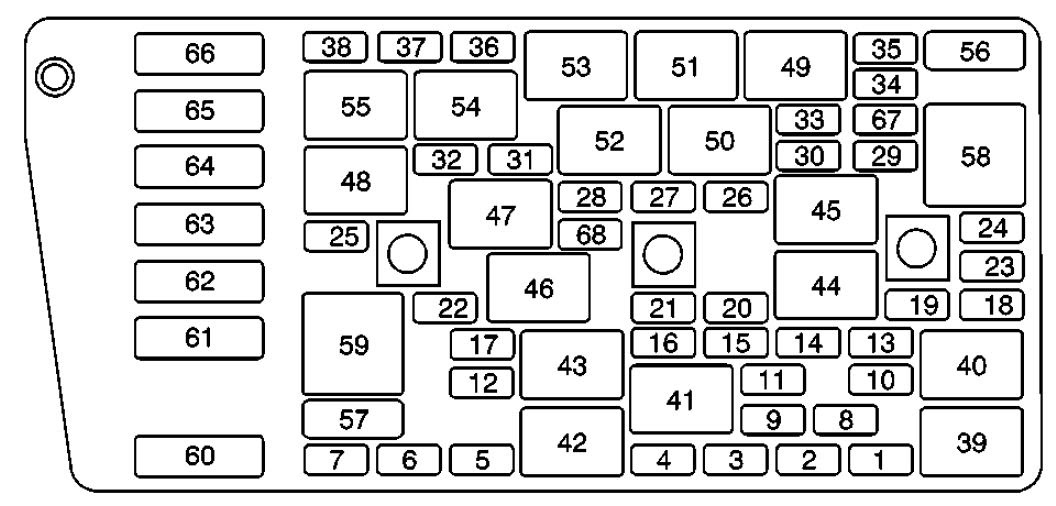
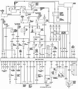 Title : 1967 Cadillac Deville Fuse Box Wiring Diagram
Category : Wiring Diagram
Format : PDF
Title : 1967 Cadillac Deville Fuse Box Wiring Diagram
Category : Wiring Diagram
Format : PDF